Contact information:
Astron Corporation
9 Autry
Irvine, CA 92618 USA
949-458-7277 from 8am to 5pm Pacific Time
Fax: 949-458-0826
Questions or Tech support: astron //at// astroncorp //dot// com
Sales or purchase questions: sales //at// astroncorp //dot// com
|
|
Note: There is (was?) an Astron Wireless Technologies, Inc. (at one
point it was called Astron Antenna Company) in Virginia, USA that makes (made?) antennas.
There is no connection between that company and the Astron Corporation in Irvine California.
|
|
|
The address in the Contact Information above is correct, there is no "St." (Street), "Blvd" (Boulevard), "Ave" (Avenue), "Drive", etc. on Autry. That section of Irvine has no descriptors on the names of the streets.
There are prices mentioned in a few places on these Astron web pages. Please use them only as guidelines as they were relevant at the time of the initial writing of this page (1999-2000) or of the individual article. Some prices were updated, some were not. We'd appreciate an email if you discover a significant change.
Astron has been making and selling linear power supplies since 1975, DC-DC converters since 1980 and switching supplies
since 1996. The basic design of the linear supplies is straight out of the Fairchild Semiconductor (the original chip manufacturer)
1968 Applications Note for the 723
regulator chip. (opens in a new browser tab)
The Pyramid Gold Series linear power supplies are similar in design and capacity
to the Astron supplies and have their own web page at this web site. The Pyramids are also based on the popular 723 voltage
regulator.
DONATIONS OF ADDITIONAL INFORMATION FOR THIS PAGE WOULD BE GREATLY APPRECIATED
(actually any page at this web site)
There is a world wide free technical mailing list / web group available to people seeking information on Astron
power supplies at https://groups.io/g/Astron.
You should read this Astron Introductory
Information article before any of the other articles here in the Astron section.
It has some very useful information on the Astron linear and switching power supplies, with
background, history, model-specific information, both repair and modification suggestions,
photos, and more.
If you came here to look for repair information on your power supply or on the one you just bought at the
swap meet please think about this:
One of the most common failure modes puts over 20 volts on the output terminals. Do you really want to risk damaging your
expensive radio by using it as a test load for a broken or unknown power supply?
Please go to this section on test loads and consider putting together something to use instead of an expensive
radio. It can be cheap or expensive; one person used a length of galvanized water pipe and some automotive jumper cables.
Troubleshooting, Repair and Modification Articles:

|
Astron understands that many of their customers are capable of repairing their supplies
and as of 2020 is now selling many of the more common
repair / replacement parts through their web site. (off-site pointer, opens in a new browser tab) The available parts include the power switch, bridge rectifiers, capacitors, pass transistors, the crowbar SCR, meters, the meter illumination kits and more . Check the Astron web site for pricing and availability. If you don't see a part that you need then don't hesitate to send them an email telling them what you have and what you need. Include a cellphone photo or two if that would help.
|

|
Repairing Astron 13.8 volt Linear Supplies by Robert W. Meister WA1MIK (SK)
General linear power supply circuit explanation, followed by the most common problems, diagnostic techniques, and repairs for these units.
|
|
|
Annotated RS35M Schematic by Jim Larsen AL7FS (169 KB PDF)
The December 2005 issue of QST had an article in their "Hands-On Radio" series titled
"Power Supply Analysis" You can
download a PDF of the QST article - it explains how a linear power supply works, and uses an Astron
RS‑35 as the "victim". Jim Larsen, AL7FS (the ARRL Alaska Section Manager)
took that QST article and went one step better — he produced an annotated schematic that takes advantage of the annotation feature of the PDF file architecture. The QST article and the annotated PDF are really worth studying. Just mouse over the yellow folder symbols and they will pop up. If your browser does not pop the notes then download the PDF and use the free downloadable Adobe Acrobat Reader to open it.
|
|
|
Troubleshooting Astron Linear Supplies by Jim Ussailis W1EQO (630 KB PDF)
From the Yankee Clipper Contest Club's "Scuttlebutt" newsletter Issue 232, August 2015.
|
|
|
Astron Linear Supply Battery Backup Modifications by Michael Morris WA6ILQ
All the schematics and modifications necessary to add a battery backup to your Astron linear power supply.
|
|
|
Installing a New Regulator Board in an Old Astron Power
Supply by By Tom Dailey WØEAJ
After his regulator board burned up, Tom bought a new one from Astron. Seems they've made a few
improvments in the design since his supply was made. This article describes what he discovered and
how to deal with putting a new board into an old supply.
|
|
|
Refreshing / Maintaining Astron Linear Supplies
by Robert W. Meister WA1MIK (SK)
Common maintenance things you can do to keep your Astron supply running for many years to come.
|
|
|
An evaluation of a 2009 Astron RS35M supply
by Stu Martin K2QDE (2.5 MB PDF)
Stu opened his brand-new supply and took several photos, showing what's been added or changed.
He scanned then redrew and corrected the schematic so it matched the actual unit; this drawing
can be found as a PDF file below.
|
|
|
Reducing Inrush (Surge) Current on Astron Power Supplies
by Robert W. Meister WA1MIK (SK)
This modification adds an inexpensive thermistor in series with the transformer, reducing the surge
current and eliminating annoying circuit breaker trips on the larger linear power supplies. This same
modification could be done to other high-power supplies. Total cost was under four dollars (in 2011)
and is a worthwhile mod for any linear Astron of 20 amps or larger.
The newer 50 amp and 70 amp supplies have a thermistor incorporated into the design and
installed during manufacturing.
|
|
|
More on Inrush Current Limiters
By Mike Morris WA6ILQ
A followup to the above article.
|
|
|
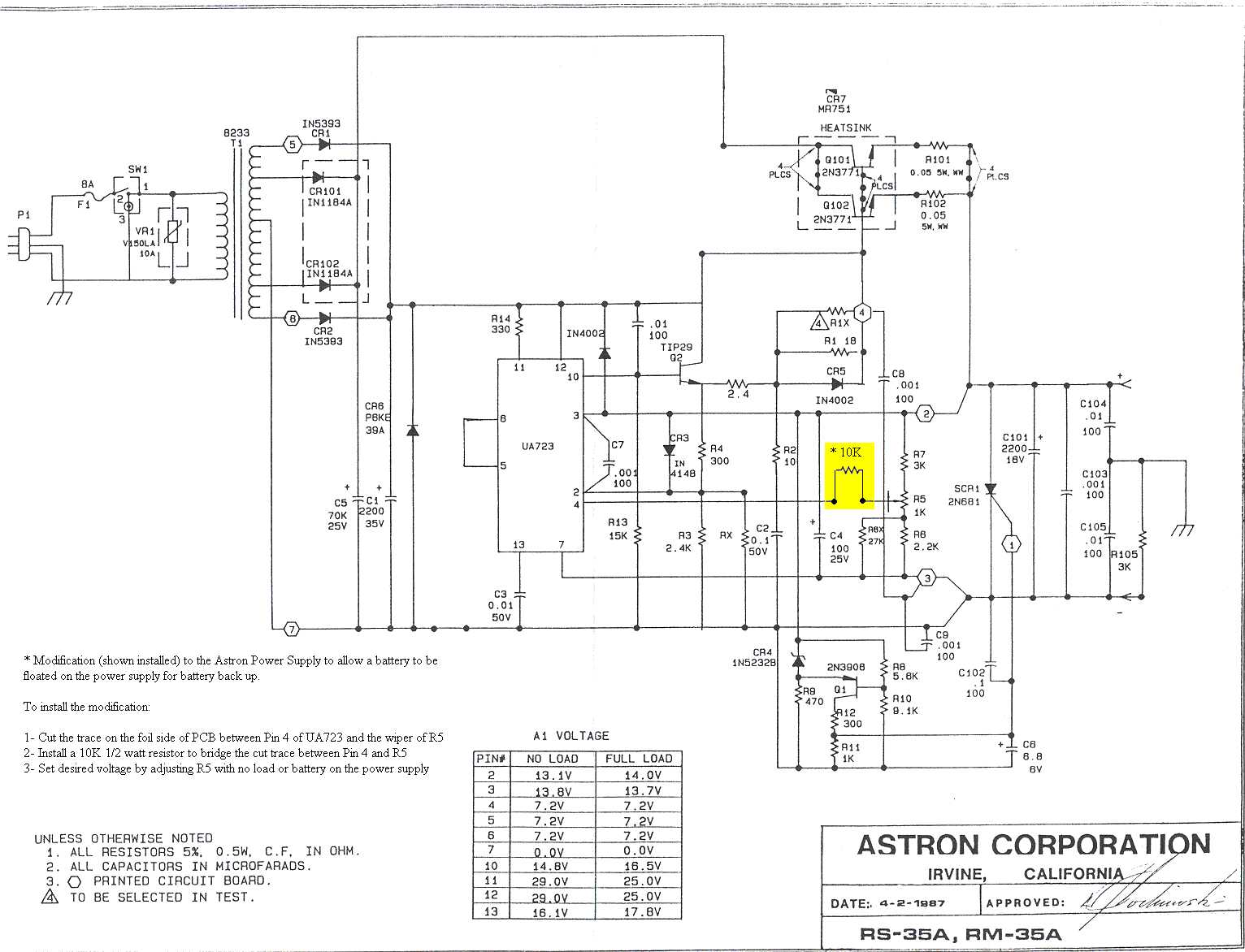
Float Modification for the RS/RM-35A/S
Schematic of the Astron RS-35A/M with float
modification (the yellow highlighted area)
While this mod was done to a 35 amp supply it will work on almost any Astron linear supply.
If you add a toggle switch to the front panel that shorts out the added resistor you
can label it "Float" (when off / open) and "Normal"
(when on / shorted).
Make sure you print the mod sheet and tuck it inside the supply for the next guy.
|
|
|
Restoring / Rebuilding an Astron RS35M
by John Keith W5BWC (1.4 MB PDF)
While John titled this as a "restoration" it's actually a complete gut job starting with the
chassis, transformer, filter capacitors, the meter and a few other parts remaining. Everything else
gets replaced with a completely different design.
|
|
|
Crowbar SCRs in Astron 13.8V Linear Supplies
by Robert W. Meister WA1MIK (SK)
A summary of SCRs used by Astron and some available replacements.
|
|
|
Main Capacitors and AC Line Fuses in Astron
13.8V Linear Supplies by Robert W. Meister WA1MIK (SK)
A summary of main filter capacitors and AC line fuses found in Astron supplies.
|
|
|
LM723 Regulator Operation by
Robert W. Meister WA1MIK (SK)
A short explanation of what's going on inside the regulator IC in an Astron power supply.
|
|
|
Understanding and Using
723 voltage Regulators by William C. Cloninger, K3OF (SK) 1.8 MB PDF
This is an article out of Ham Radio (hr) Magazine for March 1989. He shows several
homebrew supplies as he walks you through the basics. Worth reading.
|
|
|
Parallel Operation of Astron Linear Power
Supplies by Robert W. Meister WA1MIK (SK)
The secrets of that "For Parallel Operation Only" binding post on the rear panel.
|
|
|
Adjusting the Output voltage of Astron
Linear Supplies by Robert W. Meister WA1MIK (SK)
So easy, a visually handicapped (blind) person can do it!
|
|
|
Adding Front Panel Voltage and Current Adjust Pots to
an Astron 13.8V Linear Supply by Robert W. Meister WA1MIK (SK)
Turn an RS-supply into a VS-supply. Simple to do and easily reversible. Implement one or both.
|
|
|
Internal Metering in the Astron Linear Power Supplies by Michael Morris WA6ILQ
|
|
|
Replacing Astron Meter Lamps
by Larry Lockard N7FM (offsite link) (local copy)
A very well-written article that shows how he replaced the "unreplaceable" internal
meter lamps, which seem to be a pair of small 14 volt light bulbs wired in series and
powered from the raw unregulated power supply voltage.
|
|
|
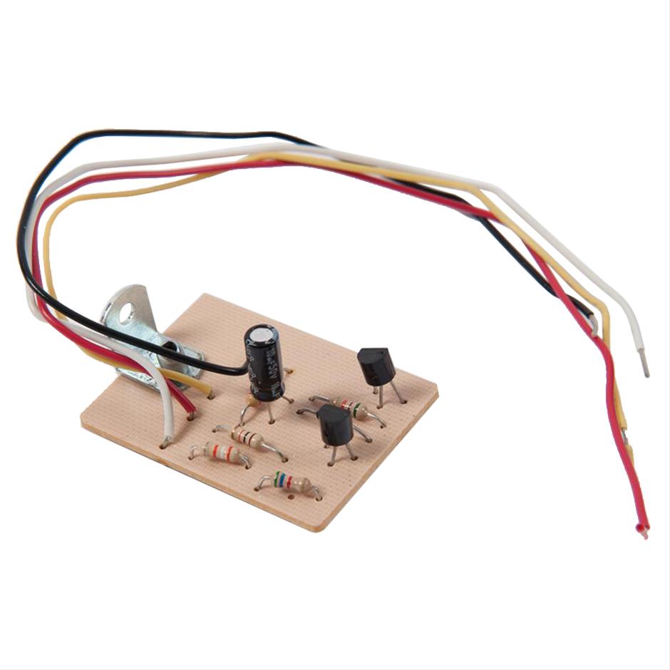
Installing Digital
Meters in an Astron Supply by Tony King W4ZT (SK) (833 KB PDF)
Tony bought a used Astron that had both of the stock meters "stuck" and not
repairable. He replaced them with digital meters and created a web page about installing
them. The ammeter he bought was a type that required an isolated power source, and
the article includes a schematic and photo of the isolated +5 volt DC source that
he built on perfboard.
|
|
|
Replacing or Adding Digital Meters to
Astron 13.8V Linear Supplies by Robert W. Meister WA1MIK (SK)
An overview of the types of meters you can buy and which ones seem to work the best in
popular Astron supplies.
|
|
|
Internal Grounding in the Astron Power Supplies by Michael Morris WA6ILQ
|
|
|
Adding Anderson PowerPole Connectors to an SS-30
supply By Robert Schulz KC6UDS
This is a very nicely done modification that extends the usability
of the SS-25 or SS-30 supply.
Kyle Yoksh KØKN took Robert's idea and modified
a Daiwa PS-304 power supply in a similar fashion.
|
|
|
Adding Anderson PowerPole Connectors and Binding Posts
to an SS-25 supply By Neil Schwanitz V73NS
Other modifications to these small supplies, similar to the ones above.
|
|
|
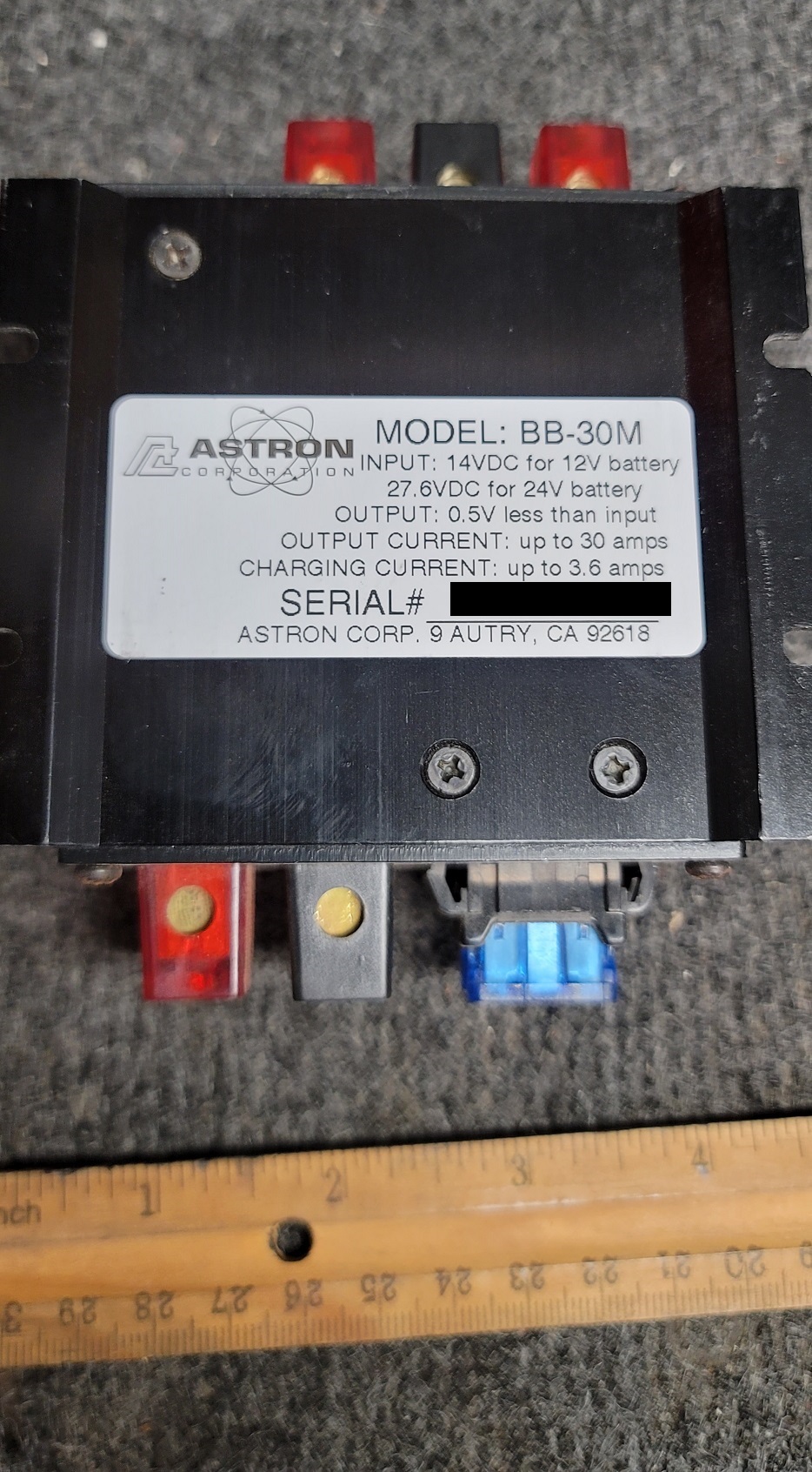
Astron BB-30M Data Sheet and schematic 346 KB PDF
Photo 1
Photo 2
Photo 3
Photo 4
Data Sheet
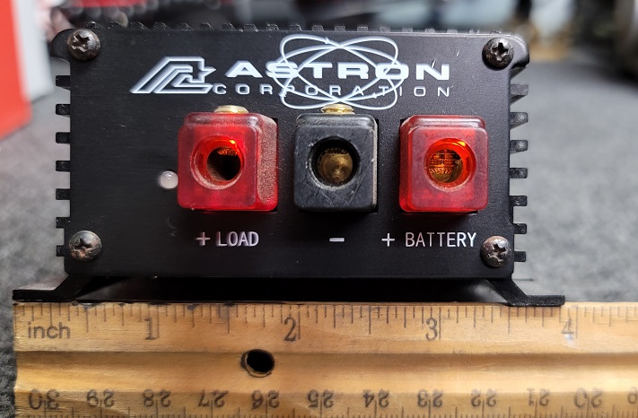
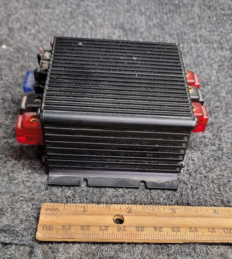
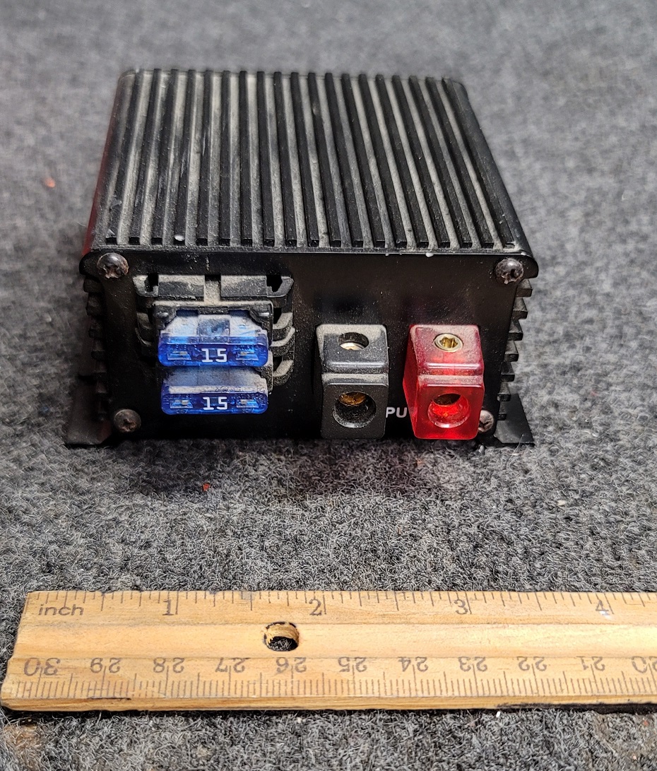
The BB-30M is an interesting and unique device in the Astron product line. It is a 30 amp stand-alone battery
backup module that works with any 12 volt or 24 volt system. It is shipped with two 15 amp
fuses in holders that are wired in parallel. There is a 5-amp mini-fuse inside for the internal curcuitry. The BB-30
switches the load from a DC voltage source to a battery upon power failure without any dropout. It also can maintain
the charge of the battery using a constant-voltage trickle charging circuit (of about 3.5 amps max and the charger can
be disabled by lifting one leg of R28, the only 22 ohm 10 watt resistor inside the box). Internally this unit
is a lot more complex than I ever imagined it would be. Note that there is about a 0.4 to 0.5 volt drop across the unit.
Samlex makes a similar product that is capable of handling 100 amps.
|
|
|
RS-50A / RS-50M / RM-50A / RM-50M Service Manual
by Astron, transcribed by Bob WA1MIK (SK) (130 KB PDF)
Specifications, circuit description, theory of operation, servicing, adjustments, parts
list, schematic for the 50 Amp rack-mount and desk-top power supplies.
|
|
|
If your linear power supply regulator board is beyond repair you can buy a brand new one from
Astron, just check the
parts page at the Astron web
site. (off-site pointer, opens in a new browser tab)
They will even ship it to you. Tell them the supply model number and they will customize it for
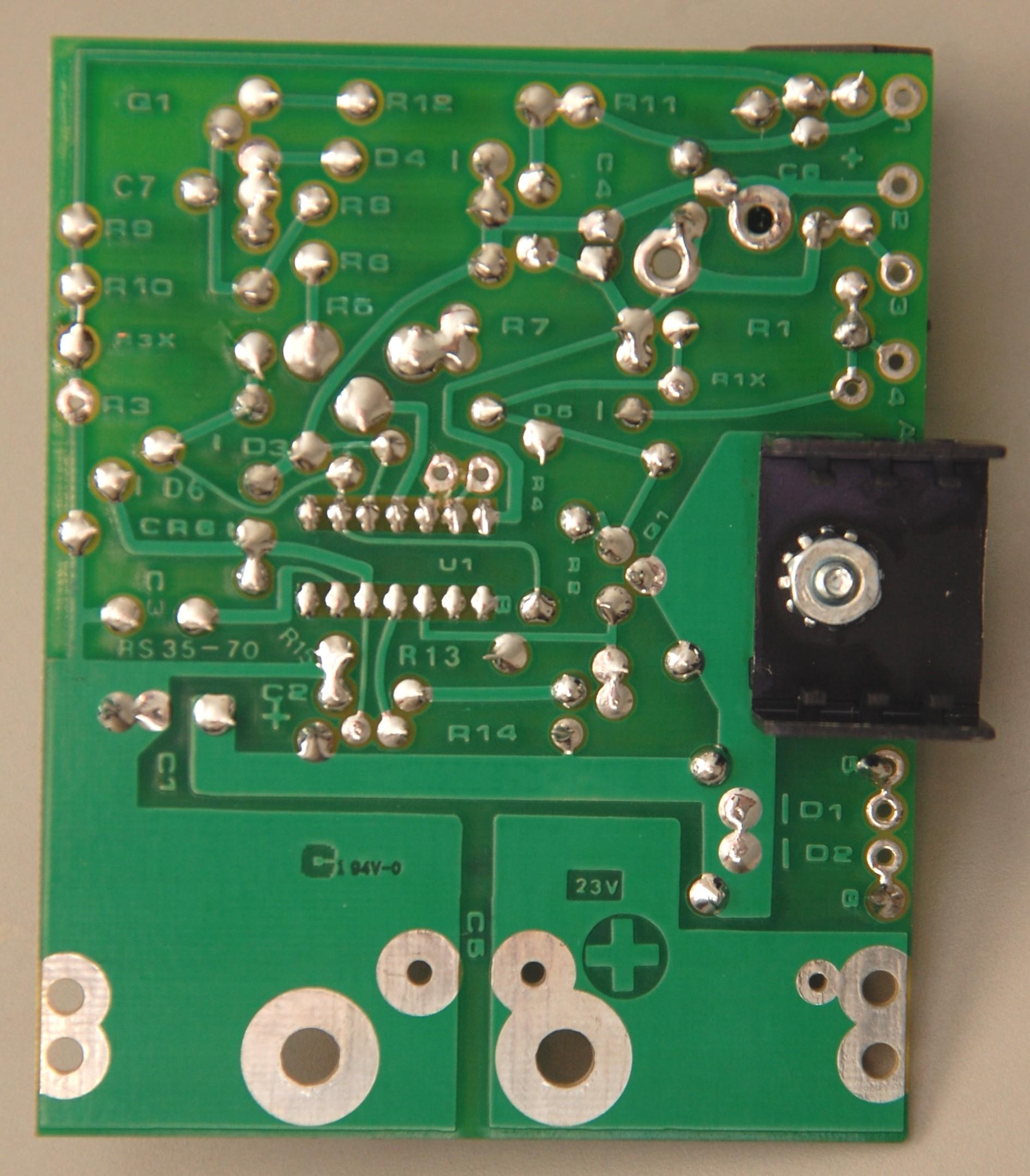
you. Here are 300 kB photos (courtesy of Bob McKinlay VE3DJ) of the
component side and the solder
side of a brand new regulator board ordered in 2014 for a VS-35 power supply. The blue adjustable
potentiometer marked "1K" on the board (visible in the component side photo above and
labeled "R5" on the solder side photo above) adjusts the power supply's output voltage,
typically from 11 to 15 volts (22 to 32 volts on 24 volt LS and VLS
power supplies). Some people realocate the blue voltage adjustment pot to the solder side of the board
as it's more accessible. Others replace it with a multi-turn potentiometer.
See the article above for a more detailed procedure.
|
|
|
Mike WA6ILQ reports that he's found two cases where the screws that
mount the voltage regulator board to the filter capacitors were not tight. Suspecting
thermal cycling he now adds star washers under the screw heads on both the + and - capacitor
connections before he puts the supply into service. Another incident had one hole of the
filter capacitor not drilled to the correct depth before tapping / threading,
and therefore the screw bottomed out and did not adequately "pinch" the circuit
board and make good contact with the copper pad. The added star washer between the screw
head and the board corrected that issue as well.
|
|
|
Stu K2QDE reports "I recently learned that very light to unreadable front panel
silk-screening existed in a number of production Astron power supplies around the time I
purchased mine in mid-2017. I searched for vendors that could make a new stick-on label.
I sent along a laser printout of an SS-55M front panel as a sample. These are plastic,
self-adhesive strips, slightly larger and brighter than factory silk-screening. The
Astron logo is slightly sharper than the silk-screened version. Perfect when refurbishing
your Astron supply. Click here to see a photo.
Contact sonia [ at ] kellylaserworks [ dot ] com for more information.
|
Crowbar Reset Circuits: Hint: Add this to any remotely located / hilltop Astron!
The Astron power supply design includes a crowbar circuit, so-called
because it essentially drops a crowbar (a dead short) across the output of
the supply.
This design is intended to save any equipment attached to the Astron in
any situation that results in a too-high voltage on the supply output. This
short is accomplished by triggering a high current SCR and the SCR, by it's
nature locks itself on. The threshold adjustment is supposed to be set to
15 volts by the factory. The later supplies have a capacitor across
the the SCR gate and ground (C102 on the RS-35 and
RM-60 diagram (opens in a new browser tab),
a 0.1µF in the RS-35 and 0.33µF in the RM-60).
This capacitor reduces false tripping of the SCR expecially in RF environments.
If your supply does not have it I'd definitely add it.
The current foldback circuit in the linear Astrons is supposed to limit
the current delivered by the supply (example: 35-36 amps in an RS-35).
But 13.8 volts at 35 amps is 483 watts and that is a LOT of
heat; neither the transistors nor the heat sink are capable of dissipating that
much power on a long term basis. That heat will cook everything inside
the Astron, which will eventually cause a major failure of the pass
transistors, driver transistor(s) and LM723 regulator IC, and that can cause
an overvoltage condition that can kill the powered device (repeater, radio, etc).
And the heat can possibly start a fire. A thermal cutout switch is a good modification.
The major problem with the basic Astron SCR crowbar design is the
lack of any method to shut the supply off when the overvoltage circuit trips.
Astron says the overvoltage protect circuit is reset by turning the power
off for between 5 and 10 seconds. The few seconds allows the
output voltage bleed down to zero and that zero voltage is what actually
resets the SCR.
One method of accomplishing this (shutting off the supply) is by adding an
additional fuse or DC circuit breaker at the output of the rectification stage –
between the collector buss of the pass transistors and the filter capacitor(s).
If this situation happens, the crowbar short on the output blows the fuse or triggers
the breaker, thereby removing the source voltage from the pass transistors and the
rest of the circuitry.
Unfortunately this mmod requires you to actually be physically next to the Astron
to power cycle it (or replace the fuse or reset the breaker), which can be very
inconvient if the Astron is at the repeater site and you are miles / hours
away.
Astron later developed an electronic reset circuit built it as an add-on module
that Astron calls an OVPR-12V. This
circuit detects the loss of output voltage (caused by the crowbar circuit activating
on an over-voltage condition). This circuit accomplishes this reset by shutting
down the LM723 voltage regulator chip for several seconds by momentarily
grounding pin 13 through a resistor. This shutdown removes the output
voltage of the Astron for the duration of the momentary ground. This zero
output voltage resets the crowbar circuit. The normal output voltage is then
restored when the momentary regulator shutdown ground is removed.
|
|
A Technical Overview of the OVPR-12V by Kevin K. Custer W3KKC
This circuit shoould have been included in the original Astron regulator board design. If you are inside
your Astron for some other reason it's worth adding this circuit as long as you have the cover off.
Just remember to print the page and leave a copy inside the case so the next guy will know what the little
circuit board is for.
|
|
|
Astron's own writeup on the OVPR-12V donated
by Joe Orrico WB6HRO (52 KB PDF)
Astron's documentation shows an extra LED indicator, which is not actually part of the OVPR-12V.
|
|
|
A photo of Astron's OVPR-12V board (found on the web).
|
|
|
An external reset circuit for the Astron Linear series A
reset circuit by Kevin K. Custer W3KKC
You can use this if you don't want to (or can't for political reasons) open up the Astron.
|
|
|
Upgrading the Astron Over-Voltage
Crowbar Circuit by Rich Post KB8TAD (offsite link)
(local copy)
While the author is repairing a VS-35 supply, his writeup is relevant to any curent value VS and the RS
series as well. There is analysis of key circuits, and info on replacing the SCR crowbar with MOSFETs.
Very well written and chock-full of troubleshooting information.
|
|
|
Fixing False Tripping of the SCR Crowbar
Circuit by Ray Maynard NØLGR
Ray figured out why some of his supplies were falsely triggering the SCR crowbar and
modified the supply to stop this from happening.
|
|
|
One useful modification: Relocate that crowbar SCR anode to the collector of
the pass transistors (the output of the rectifier stage), and after a new high current fuse. Better yet,
put in a manually resettable circuit breaker, as murphys law says you will blow the fuse and have
no spares, and they ALWAYS blow at the worst possible moment…
If the SCR trips and the supply does not go into current limiting, you can kiss the
current meter and expensive current sense resistor / ballast resistor goodbye.
And this goes hand-in-hand with the above: If the crowbar is located before the series pass
transistors, it is a good idea to put a reverse biased diode across the series transistors (CR7
on
the RM-60 diagram), which
would discharge any large capacitors on the
regulated side through the crowbar. Without the diode, the collector side would be at zero
volts after the crowbar tripped, but the emitters could still be at at +12 Volts due to
any large capacitors on the regulated side (perhaps inside the supplied device or any situation
where the Astron is float charging a battery). Astron uses a 10 amp 100 volt
diode. If you find it missing in your supply (common) I'd use something
larger – maybe a 20 amp diode.
|
Load Testing / Testers:
Once you've repaired your power supply you need to test it. Do you really want to risk your
expensive HF, VHF or UHF radio as a test load? I didn't think so.
A common method of testing is a number of tungsten light bulbs. They have a low (almost
zero) resistance when cold, and will look like a dead short until they warm up. This
characteristic can false-trigger the overcurrent sensor and shut down the supply. One
way around this is a low resistance 0.1 to 0.5 Ω resistor in series until bulbs
are glowing and then jumper it out.
|
|
A Tutorial On Power Supply Load Testing By
Eric Lemmon WB6FLY (SK)
Worth reading… Eric was a regular poster on the repeater-builder mailing list for over a decade. He did a number of power supply tests
and posted his results. Someone asked him what tools he used and how did he perform the tests and this document was the result.
|
|
|
Power Supply Dummy Load by Tony King W4ZT (SK) (125 KB PDF)
Tony designed and built a test load made up of common 12 volt automobile stoplight bulbs. You can get them cheap
from a do-it-yourself (sometimes called a "pick-a-part", "pick-your-part" or "you-pull-it")
auto junkyard. Don't go cheap and leave off the top protection plate, the stoplight bulbs get very hot very quickly and can
give you serious burns. This is the voice of experience of your page maintainer.
|
|
|
High Power DC Load for Power Supply
and Battery Evaluation by Phil Salas AD5X (1.53 MB PDF)
This is from the October 2006 QST. Take this article as a source of ideas, an AC fan may be cheaper.
And this unit has a lot of heat generating ability, you might want to consider using open construction like the unit
Tony King built.
|
|
|
A cheap "carbon pile" tester made for car batteries like
this one
from Amazon is not appropriate for testing power supplies as there is no adjustment for the current. They are also
designed for quick tests – 10 to 15 seconds at a time with a long cool-down period. There is a manufacturer
that makes one in the $50 to $60 range (2024 price) that has two meters and a "500 amp" current adjustment but
the one I borrowed and tried to use was flimsy and the current adjustment was very, very touchy to the point of being unusable.
|
|
|
Your page maintainer once saw a test load made up of a number of old automobile headlights, with
one pull-push headlight switch per bulb (like the switch used in a 1960s-1970s Fords or Chevys). The owner had
bought the bulbs, sockets and switches from an antomobile junkyard. Each switch controlled one
headlamp - when pulled half way out the low beam came on and when pulled all of the way out both
the low beam and the high beam were connected.
|
|
|
While the article is an evaluation of an Astron supply there is
an interesting homebrew
test load shown here that uses automobile halogen light bulbs (look at the second photo from the top).
Be careful, halogen bulbs can get much hotter than tungsten bulbs. (Off-site pointer, the link
opens in a new browser tab)
|
|
|
Another alternative is to duplicate what the page maintainer observed at a shop vist over 20 years ago.
A homebrew test load was made up of a number of low-ohm / high-wattage resistors with a
number of knife switches for switching each segment of the load on and off.
The resistors and switches were bolted to a (roughly) two and one-half feet long length of railroad rail
fastened to a piece of one inch plywood about three feet by two feet with a heavy caster on each corner.
Yes, it was very heavy! (over 100 pounds of steel!) The owner joked that the rail was "cheap thermal mass".
See if there is a rail yard near you then find the foreman and politely ask if there is a short length of scrap
rail available. It could even be worn out rail. North American railroad rail weight is measured in pounds
per yard (or kilograms per meter), and most USA rail is from 115 to 147 pounds per yard which
works out to 38 to 49 pounds per foot (the weight depends on the use, main line is the heavier rail,
a spur behind a warehouse or a rail car storage spur could be the lighter rail).
Note that if you never ask they can't say Yes! The obverse of that is if you never ask the answer is
always No! And what is the worst that could happen? They say No!
If you can't source a chunk of rail then you will have to find another form of large heat sink. Ask around
and see if anyone has a large heat sink from a dead solid state HF, VHF or UHF RF power amplifier, like
from an MSF5000.
Once you have your heat sink there are eBay and surplus sellers that have metal body power resistors in
values of 0.1 ohm, 0.22 ohm, 0.33 ohm, 0.47 ohm, 0.68 ohm, 1 ohm,
2 ohms, 3 ohms and many higher values and in wattages from 5 watts (under $3),
10 watts, 25 watts, 200 watts, 300 watts (under $30),
and 500 watts (under $40). (2024 prices)
As an example, look at this
seller on ebay (there are others) and look at the options on ohms and watts. (off-site pointer,
the link opens in a new browser tab) You mount the resistors to the heat sink with thermal
compound (just like you would mount a power transistor).
Note that you'd want to use an appropriate wire gauge connecting cable between the supply and the
load. Stranded welding cable is a good choice. And on each of the below you'd want to
add a fan!
- An RS-12 at 13.8 volts would need a one ohm and a 0.22 ohm resistor in series to total
1.22 ohms, pull 11.3 amps. Close enough!
The one ohm resistor would dissipate 128 watts and the 0.22 woudl dissipate 3 watts.
I'd use the 200 watt unit for the one ohm and a 10 watt for the 0.22 ohm for a total
of under $10… plus an optional knife switch.
- An RS-20 at 13.8 volts would need four 3 ohm resistors in parallel to effectively make a 0.75 ohm
resistor and provide a load of 18.4 amps. Close enough! There is about 254 watts being dissipated
hence the four resistors, or about 65 watts per resistor. I'd use the 100 watt units for a total of under
$15… plus an optional knife switch. If you split the load in half with a second knife switch you
could have a 9.2 amp load which would be suitable for testing an RS-10.
- An RS-35 at 13.8 volts would need a 1 ohm and a 0.68 ohm resistor in parallel to provide
a load of 34.1 amps. Close enough! There is about 470 watts spread across both resistors, but
the 0.68 ohm one is dissipating 280 watts so I'd use the 500 watt units for a total of
$72… (plus a pair of knife switches, one would give you a 13.8 amp load, the other would give you
a 20.3 amp load)
- To test an RS-50 set for 13.8 volts you could use a 0.68 ohm and a 0.47 ohm resistor
in parallel provide a load of 49.6 amps and 685 watts. Close enough! But that's 405 watts in
the 0.47 ohm resistor so you'd want to use 500 watt resistors for both and that's a total of $72…
And I'd use at least 8 gauge cable, if not 6 gauge. (plus a pair of knife switches)
- An RM-60 at 13.8 volts could use two 0.47 ohm resistors in parallel creating a 58.72 amp
load. Close enough! However that's 405 watts in each resistor and you'd want to use the 500 watt
units for a total of $72… If you wanted more headroom on the load you could use four in series-parallel
for $144. Either way I'd use 6 gauge or maybe 4 gauge cable. (plus a pair of knife switches, each
would give you a 24.36 amp load)
- To test an RS-70 at 13.8 volts you will need to dissipate almost 970 watts! Yes, thre are
500 watt resistors available, but you will need several. Ome configuration that provides versatility is
five 1 ohm resistors in parallel with a switch on each one… They would provide a load of
13.8 amps with one resistor, 27.6 amps with two resistors, 41.4 amps with three resistors,
55.2 amps with four resistors or 69 amps with all five resistors. Close enough! Each resistor is
dissipating 190.44 watts, you would be too close using 200 watt resistors, 300 watt units
(5 for $141.55) would be OK for intermittent testing, 500 watt units ($180) would give you some
headroom. And I'd definitely use 4 gauge or mabe even 2 gauge cable. Plus five
knife switches.
- You can get inexpensive high current knife switches from
this seller on Amazon.
You can get red and black copper welding welding cable from
another seller on Amazon. (both links are off-site pointers, both open in a new browser tab)
The options include 5 feet of each color in 6 gauge) for $24, 5 feet of 4 gauge for $30, and 5 feet of 2 gauge for $40. (2024 prices)
This is not the really good oil-proof rubber jacketed welding cable, it's inexpensive PVC but very flexible cable as it's made from 30 gauge strands.
Here's a wire table that includes AWG versus amps.
- None of the above cases would be considered continuous duty, especially if you don't have fan or other cooling!
|
|
|
Another test load that your page maintainer witnessed was used on an RM-50 or RM-70 supply. The
load was a long length of galvanized 1/2 inch water pipe in a "U" shape and the owner used a set of automobile
jumper cables. He clamped the negative cable to one end of the pipe, and then slid the positive jumper cable starting
at the far end along the pipe until he had the desired amps of current flow, then clamped it there.
|
Power Supply Model Information:
Please realize that you will find multiple different schematics listed below for the same
supply as the designs changed over the years due to parts availability, circuit improvements,
etcetera. For example, the early supplies use discrete stud-mounted diodes instead of half of
a bridge rectifier (switching to an epoxy bridge module, despite the fact that only half is
used, is one of the tricks that the designer at Astron used to lower the parts cost and
manufacturing labor cost). You may have to download more than one schematic to get the one
that matches your supply, and you may not find your schematic at all (as we only have the
ones that were donated to us). If you have one that we don't, please consider emailing us a
high resolution scan. Or just send us the schematic by postal / snail mail and
we'll scan it and return it. Send it to the maintainer listed at the top of this page.
When (or if) you find the schematic that matches your unit I suggest you print it and stuff
a copy inside a plastic page protector, and tape it to the underside of the lid of the power
supply cabinet! Several folks have mentioned in emails and on mailing lists that you can call
Astron on the phone and you will hear them tell you that they don't have electronic copies of
their drawings and they don't know how to email them. Trust me, the person that answers the
phone will be amazed when you tell them that the drawings from different years for the same
model power supply show some different component IDs and values. Unfortunately this is
important because if one chooses to buy replacement parts (from Astron) they (according to
Astron) need only supply the model and component IDs. Fortunately everything but the filter
caps, transformer, the bare regulator circuit board and the metal cabinet are common Mouser
or DigiKey parts, and I bet you could find the capacitors if you tried hard enough.
Astron has to get them from somebody.
Update: The above paragraph was written about 2000-2004. Things are much better now.
Variable output supplies are identical to the non-variable supplies except for the two
front panel adjustment controls. Similarly, supplies with meters are identical to those that
don't have meters except for the meters, calibration pots, and possibly a DPDT switch used
on supplies that have just one meter for amps and volts. So while you may not find an exact
schematic for your particular unit, if you find one for a variable or metered supply, use
that one.
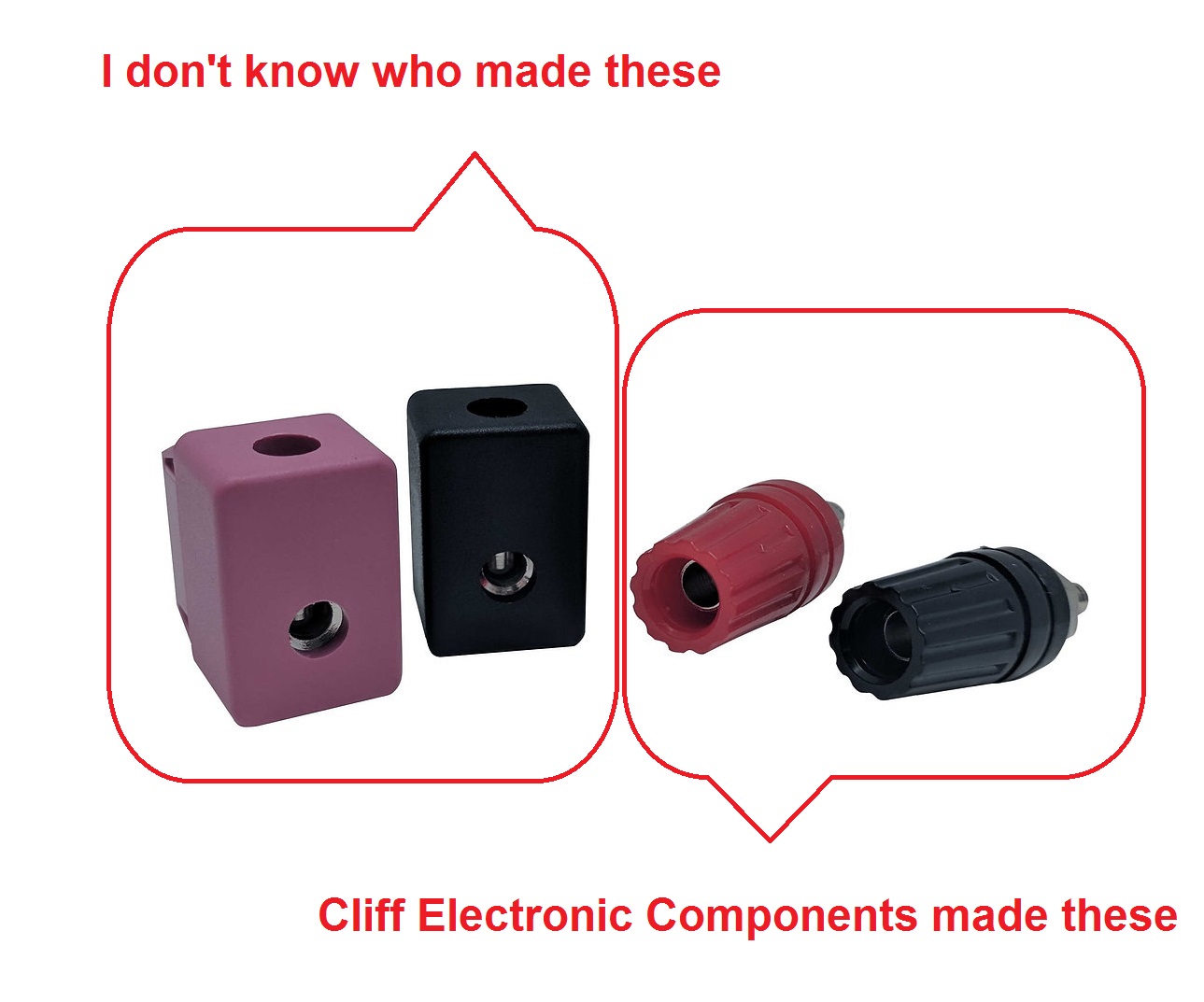
Low Current Output Terminals (Binding Posts and Block Terminals): Supplies rated for 12 Amp or less (SS-10,
SL-11, or RS-4, RS-5, RS-7 and RS-12) have either two two 4 mm, 15 Amp, 3-way binding posts
or block terminals with setscrews on the rear for output terminals.
The binding posts are mounted in 1/4 inch holes with keyways and are made by Cliff Electronic
Components as their Model TP1. They are available from www.Newark.com and other suppliers.
The setscrews in the block terminals are brass with slots (i..e not allen or phillips head) and if you turn
them too hard you will break off one side of the slot. This is the voice of experience.
Astron sells replacements on their web site for about US$4 each (in 2020). Just take the
cover off the supply, disconnect the block then remove it and replace it – but first replace the
slotted brass setscrews with an allen head screw! Astron has fixed this, the newest Astron
supplies have the same connection blocks but with a different setscrew. And as a result the replacements
sold by Astron also have the new setscrew.
Click for photo.
Hex bolt outputs: Supplies rated for higher current (the RS-20, for example)
usually use 1/4-20 threaded hex bolts with flat washers, split lockwashers, and hex nuts
for output terminals. Swapping the hex nuts for wingnuts is a popular and inexpensive
modification. The wing nuts are available at almost any hardware store, (even Home Depot).
Your author / page maintainer found them at his local Ace Hardware.
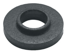
Replacement shoulder washers: One or both of the output terminals are insulated
from the chassis with a
fiber shoulder washer
that fits into a 5/16 inch hole (Keystone #4711).
Mouser stocks them as item 534-4711, DigiKey's part number is 36-4711-ND.
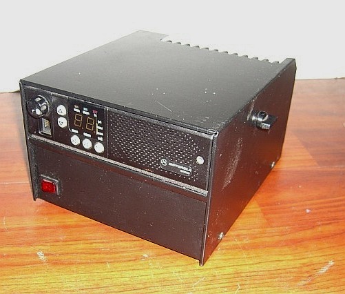
Some of the Slim-Line (SL) supplies, especially those models that have a metal sleeve that holds
a specific model radio have a cable and connector appropriate for the radio that it would normally
power. The supplies built for Motorola frequently have a 120 / 240 volt AC
switch and other model spacific differences… the Motorola HPN9041 is an SL-15M variant
and has a 120/240 volts switch and no binding posts. Instead it has two pigtail cables, one with a 6-pin Molex connector, the other with a 2-pin SAE (trailer) connector. It also has insulating plastic caps on the two pass transistors.
Notes about Serial Numbers:
For years the year of manufacture was the first two digits, the month was the next two digits,
and the remaining digits are a sequential number that's assigned to each unit. We're not sure if it's
model-specific or the total number of all units made that month by Astron. This date code
information was confirmed by Astron. However…
Recently it was pointed out that serial numbers like 202050xxx were showing up. Now you and I both
know that there isn't a 20th month… We've dropped a note to Astron and are awaiting a reply…
Notes about Model Numbers:
The model number is constructed from a prefix (letters), a peak current value (digits),
and a suffix (letters). Look for a schematic based on the current value first. The circuitry
is similar for the different prefixes and suffixes. For example, the Variable power supplies
with front panel controls just add two potentiometers. Any supply could have meters added,
if they'll fit on the front panel. These don't affect the basic circuitry.
Prefixes:
- An "RS-" prefix is a standard desk-top Regulated Supply.
- An "RM-" prefix instead of "RS-" prefix indicates a Rack-Mount
power supply (i.e. packaged to mount in a 19 inch rack). This packaging is only offered on the
higher amp supplies.
If you need to rack mount a smaller one, just use a rack shelf. Other than the meters and the
attached adjustment trimpots there is little electronic difference between the RS- series and
the similar RM- model.
- A "VS-" or "VM-" prefix indicates a variable version of a
"RS-" or "RM-". Just remember that V = Variable.
Converting your "RS-" or "RM-" to "VS-" or
"VM-" with front panel adjustments usually involves adding two
potentiometers to the front panel and making the minor wiring changes shown in the
schematic. See the article by Bob Meister WA1MIK (SK) elsewhere on this page.
- SL- series are Slim-Line or Small Linear power supplies. Their schematics are further
down the page. These are often found inside a larger (vertically) enclosure that has room for
a two-way radio to be mounted above the supply. The LMR (commercial two way radio) world
calls a mobile configured as a base a "control station". The SL-series power supplies are also
found in some small desktop repeaters that use a pair of mobile radios.
Like the other Astrons the suffix characters indicate the peak current capacity and/or the
make and frequently the manufacturer of the radio that fits the enclosure. Check the catalog
pages on Astron's web site for the relevant details.
- LS- and VLS- series are Linear Special-voltage and Variable Linear Special-voltage
power supplies, usually 28 volt. They will adjust down to 22-23 volts for use
with 24 volt equipment.
- LSRM- and VLSRM- series are identical to the LS- and VLS- supplies except are Rack-Mount.
- SS- series are Small Switching power supplies. Their schematics are further down this page.
- SRM- series are SS switching power supplies in a Rack Mount configuration.
- SLS- are Switching Special-voltage power supplies, usually 28 volt.
- SLSRM- are Switching Special-voltage power supplies, usually 28 volt, in a Rack Mount configuration.
Like the LS- and VLS- series they will adjust down to 22-23 volts for use with 24 volt loads.
Suffixes:
- A trailing "A" seems to be the default if there's no other suffix. Some models have this, some don't.
- A trailing "R" seems to be used for power supplies that were sold with an
enclosure that could accept a mobile radio, usually only found on the SL-series.
- A trailing "M" indicates front panel Meters. If the supply has the "M"
suffix, those under 20 amps usually only have room for just one meter. 20 amp and
35 amp supplies are physically large enough that the front panel could have one or two meters.
50 amp and larger supplies almost always have two meters.
Slim-line (SL) supplies usually don't have room for meters.
Switching supplies (SS) 25 amp and larger usually have two meters.
Newer supplies (starting around 2008) could have illuminated meters. We don't know what the
determining factor is for a model to have illuminated meters…
The newest "M" switching supplies have a digital meter that displays both voltage and current.
- A trailing "L" indicates there's a cigarette Lighter socket on the front.
- A trailing "S" indicates there's a Speaker inside the case.
- A trailing "BB" indicates the Battery Backup option.
- A trailing "RM" indicates Rack Mount, often for high amperage, occasionally for dual supplies.
- A trailing "AP" indicates a pair of Anderson PowerPole connectors on the front panel.
These seem to be available (so far) on a few fixed-voltage desktop models: RS-20M,
RS-35A, RS-35M, and as an option on the SS-25, SS-30, SS-50.
Of course there's nothing preventing you from adding Andersons to the front, rear or both of your Astron.
- A trailing "220" (or "240") indicates the supply operates on 220-240 volt line voltage.
Astron builds supplies specifically for several manufacturers of radios - some without and some with custom modifications.
For example, the Astron LSRM-25A is simply relabeled for Uniden as the ARX-330. It is a rack-mount 28 volt linear power
supply good for 18A continuous, 25A intermittent. The only difference is the name on the front.
The Motorola HPN9041 (45 KB PDF) is an SL-15M variant. It has a 120 / 240 AC switch…
Other OEM products are the Kenwood KPS-12, based on the Astron RS-12, the Motorola RRDN6933A is an RM-35A-BB
and Astron also builds custom supplies for GE, Harris, Icom, E.F. Johnson, Kenwood, Motorola, Uniden and Vertex.
Another example, the Astron SL-11RRA is a 13.8 Volt 11 Amp unit specifically designed with
a metal sleeve mounted on top of the cabinet.
Multiple sleeves are available, one that the author has is specifically sized so that a MaxTrac, Radius LRA or GM300 mobile can
slide into it; (click here for a photo).
Astron sells the sleeves separately on their web site.
A conversion list of 65 different Motorola power supplies to Astron model numbers can be
found here.
Schematics:
If you don't find the schematic for your Astron below, then we were not given it.
If you find a PDF somewhere else that we don't have, we'd appreciate an email with it. If you find a
paper copy we'd appreciate a scan (at the highest resolution your scanner can do) sent via email.
Or just send us the schematic by postal / snail mail and we'll scan it and return it.
Send it to the maintainer listed at the top of this page before you send it.
Astron model numbers indicate the peak (intermittent) current that can be drawn from the
supply. Depending on the model the continuous current is somewhere between 40 percent
and 80 percent of the peak current. For example, an SL-15M is rated 14 amps peak
but only 7 amps continuous, yet an RS-20A is rated 20 amps peak but only
16 amps continuous. The absolute maximum current where foldback limiting occurs is
usually 10 percent to 30 percent above the peak current rating.
The newer switching supplies have a higher continuous rating, for example a SS-50 is rated
at 50 amps intermittent, 40 amps continuous. However I'd add a fan…
The available output current on the VS-series depends on the heat sink dissipation and
therefore the output voltage. You get much less deliverable current at a lower output voltage.
This derating is due to the power dissipation capability of the heat sinks and transistors on
the back or sides of the supply. At lower output voltages, there's more voltage across these
transistors, so they get much hotter. Current foldback may also occur earlier at these lower
voltage ratings, so beware. The Astron catalog has these derated current specs. If you plan
on using a VS-series at a low voltage you'd be smart to add a thermostatic-switch controlled
fan blowing across the heat sink(s).
Specific Examples: A VS-50M supply is rated for 37 amps continuous at 13.8 volts DC
but only 22 amps continuous at 10 volts DC and only 10 amps continuous at
5 volts DC output. The other VS-series supplies must be derated similarly.
Important Notes: Numbers in many of the schematics below may be blurry (particularly
the pin numbers on the 723 regulator IC). The scans are what we were given.
Here's what to look for and how to resolve it:
A blurred pin "3" could look also look like a "6" or an "8". but pin 3 of the 723 chip always goes to the "+" output connection of the supply.
A blurred pin 6 can look like an "8". Luckily there is nothing connected to pin 8
of the 723 chip as it is a NC (unused, no connection) pin and pin 8 is rarely shown on any of the Astron schematics.
If you see something that looks like an "8" it's most likely a "6" where the top got closed up by the blur.
Pin 6 is always bridged (connected) to pin 5 on an RS- supply, and both pin 5 and 6 are connected to the current limit potentiometer on a VS- supply.
The voltage charts on most of the schematics follow this scheme. You can always check
some other schematic(s) if you can't read the one for your particular supply as they're very
similar, especially around the 723 chip.
If you happen to have a cleaner copy of a blurry schematic please send us a good clean scan
(at the highest resolution that your scanner can do), or send us the schematic by
postal / snail mail and we'll scan it and return it. Send it to the maintainer listed
at the top of this page.
The resistor in the schematic that is marked R3x or Rx (in parallel with R3) sets the maximum
current allowed before the fold-back current limiting comes into play. The value is unique to
each model and depends upon the actual maximum current handling capabilities of the model.
There is more discussion of R3x or Rx in the currrent control section of the article
titled "Adding Voltage and Current Adjust Pots to an Astron 13.8V Linear Supply"
that is linked above.
Linear Power Supply Schematics:
Donations of additional schematics for the library below are always
welcome !! Send them to the maintainer listed at the top of this page.
|
|
RS-3A and RS-4A 300 KB, dated 12-1989
donated by Oscar Ramsey NV3G
The RS-5A is most likely the same. The regulator board in a 2010 RS-5A supply seems to
be used in the 3A, 4A, 5A, and 7A supplies, however there are no crowbar components installed
in the 3A, 4A, and 5A supplies. (The draftsman obviously started with the RS-7 schematic;
he forgot to adjust the voltage table. It shows a 7 amp load.)
|
|
|
RS-7A 70 KB, dated 10-1994 donated by Mike Morris WA6ILQ
|
|
|
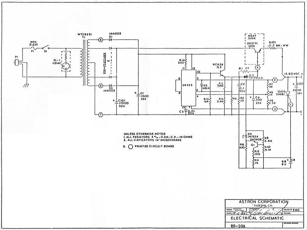
RS-10A, RS-10S 105 KB, dated 09-1981 donated by Bill Netzlof KL7IGB
|
|
|
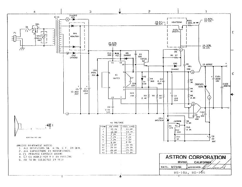
RS-10A, RS-10S 368 KB, dated 09-1988 donated by George Franklin WØAV
|
|
|
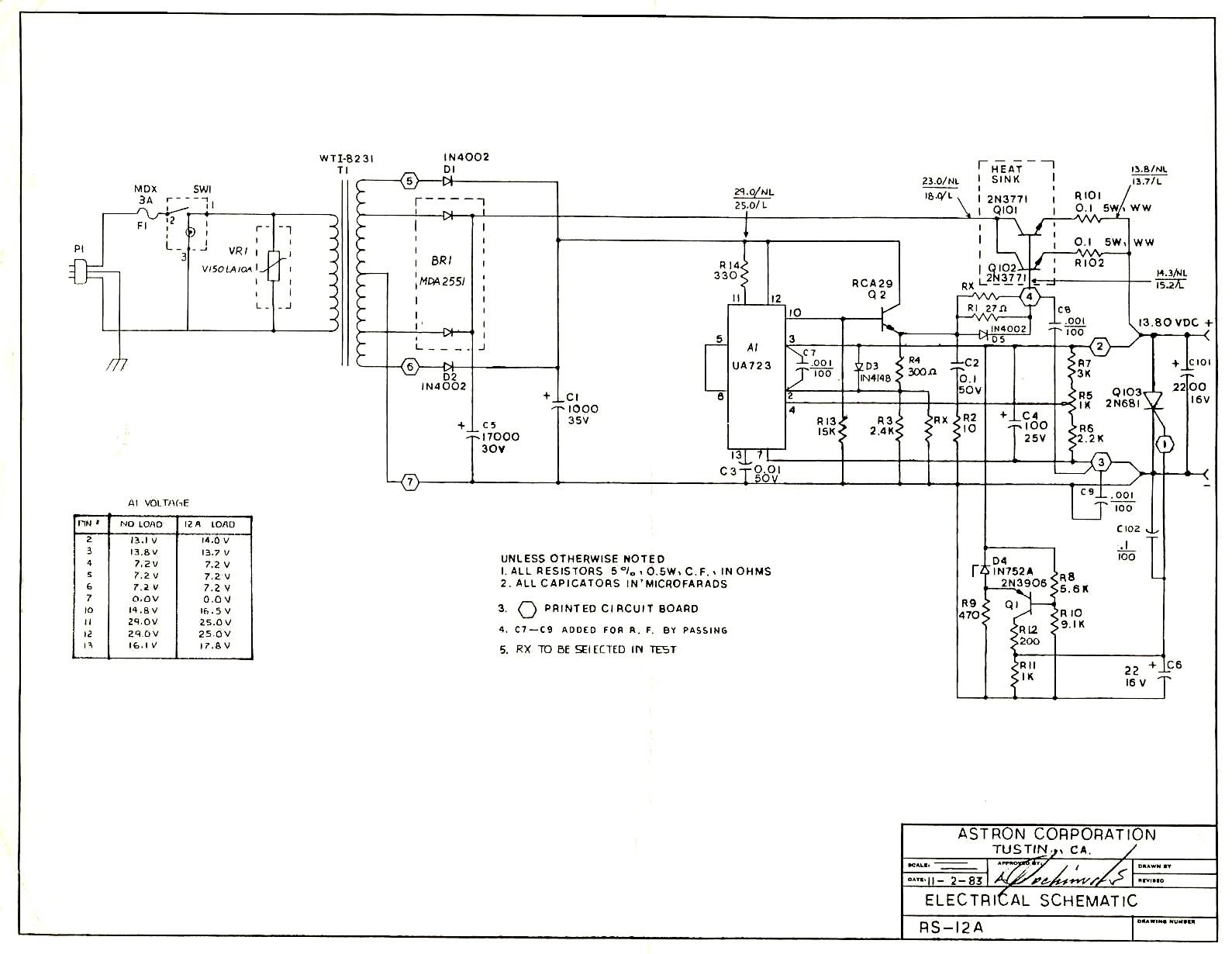
RS-12A 199 KB, dated 11-1983 donated by Richard Reese WA8DBW
|
|
|
RS-12A, RS-12M 127 KB, dated 06-1988
|
|
|
RS-12A, RS-12M 31 KB PDF, also dated 06-1988 donated by Mike Morris WA6ILQ
|
|
|
RS-12A-BB 119 KB PDF, dated 01-2000 donated by John Lund.
See the comments above on the battery backup feature.
|
|
|
RS-12A, RS-12M 71 KB PDF, dated 11-2009 donated by Greg Shaw N4GOS
|
|
|
RS-20A 71 KB, dated 11-1978 donated by Gary Eldridge KC8UD
|
|
|
RS-20A, RS-20S 79 KB, dated 09-1988 donated by Kevin Custer W3KKC
|
|
|
RS-20A, RS-20S 185 KB, dated 09-1988 donated by Mike Morris WA6ILQ
|
|
|
RS-20A 44 KB PDF, dated 01-2000 donated by Ron N8HXR
|
|
|
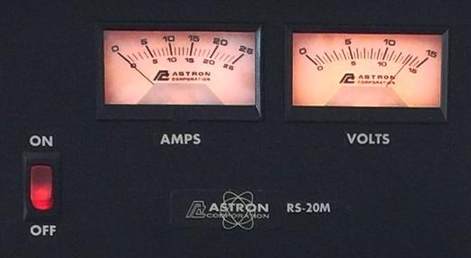
RS-20M 117 KB PDF, dated 01-2000 donated by Ron N8HXR
|
|
|
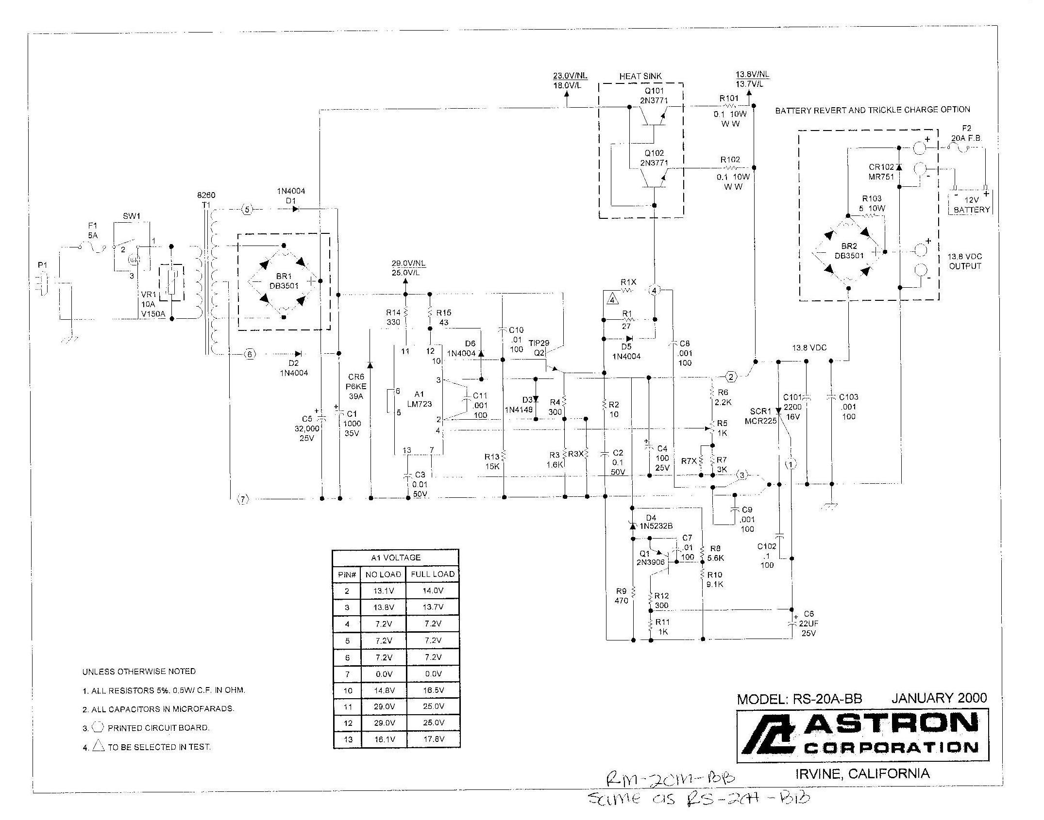
RS-20A-BB 330 KB, dated 01-2000 donated by Rick Williams N8EDR
See the comments above on the battery backup feature.
|
|
|
RS-20A 391 KB, dated 04-2020 donated by David Proctor, Jr. KY4WI
|
|
|
VS-20M 26 KB PDF, dated 11-1978 donated by Bob Burchett WB6SLC
|
|
|
VS-20M 80 KB PDF, dated 09-1986 donated by Doug Marston WB6JCD (SK)
|
|
|
VS-20M 78 KB PDF, dated 01-2000 donated by Larry Horlick VYØHL
This supply is also known as a Motorola RRDN6082A. The Moto invoice said "VS-20ML".
|
|
|
RS-35M 135 KB, dated 02-1976 donated by Robert Hassell KA5ZCI
This is the single meter version with a DPDT switch to select voltage or current.
|
|
|
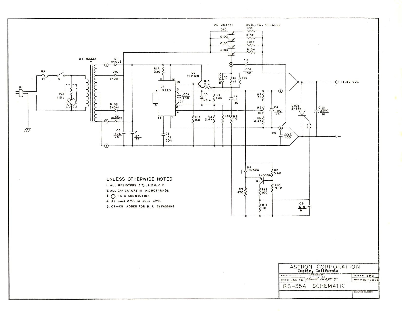
RS-35A 135 KB, dated 01-1978 donated by Joe McIntyre W4DEX
|
|
|
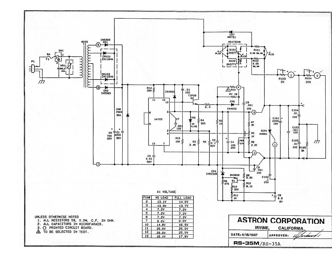
RS-35M 46 KB, dated 04-1987 donated by Kevin Custer W3KKC
|
|
|
RS-35A, RS-35M 216 KB, also dated 04-1987 but different than the above RS-35M. Donated by Mike Morris WA6ILQ
|
|
|
RS-35M 47 KB, dated 04-1987, again different. Donated by Mike Morris WA6ILQ
Thanks go to Ed Lambert K1ZOK who pointed out in an email that there was an important error in
this schematic file (WA6ILQ edited the image file and corrected it).
There was an extra connection line drawn between the collector of the TIP29 and the
base connections of the pass transistors. This wire shorted out the regulator driver
transistor (Q2). If you downloaded this schematic in the past you may want to
download a fresh copy and replace your incorrect copy.
|
|
|
RS-35A, RS-35M 555 KB PDF, dated 09-1988 donated by Jim Bacher WB8VSU
|
|
|
RS-35A, RS-35M 159 KB PDF, dated 05-1991 donated by Mike Morris WA6ILQ
|
|
|
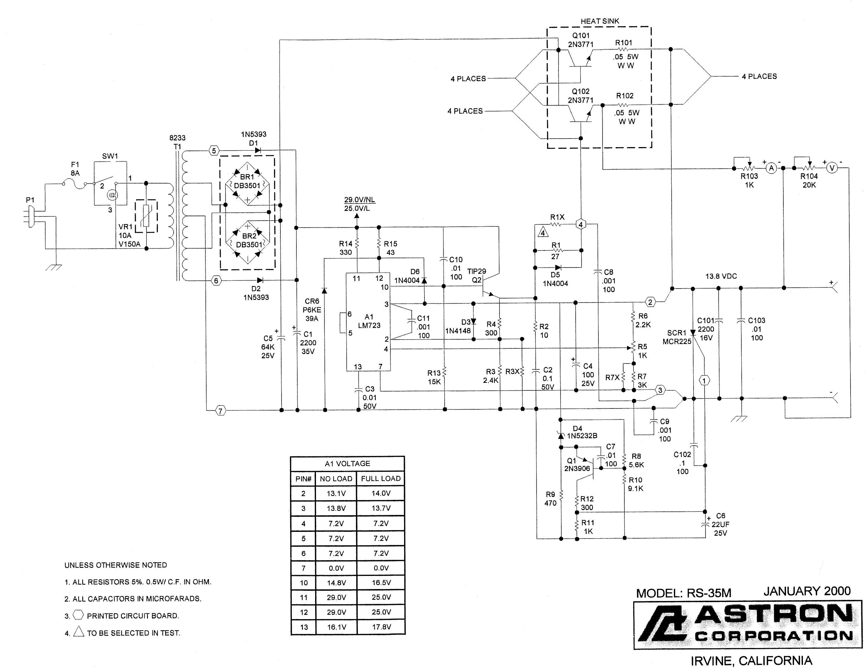
RS-35A, RS-35M 46 KB PDF, dated 05-1995 donated by Mike Morris WA6ILQ
|
|
|
RS-35M 498 KB, dated 01-2000 donated by Neil McKie WA6KLA (SK)
|
|
|
RS-35M 78 KB PDF, dated 10-2009 redrawn, corrected, and donated
by Stu Martin K2QDE
Includes meter illumination.
|
|
|
RS-35M 127 KB PDF, dated 02-2017, drawn by Larry Joy WN8P
This is an actual as-built schematic, drawn from scratch to current IEEE specifications, of an older (1978) RS-35M supply
with one meter on the front, stud rectifiers inside, and the TIP29 driver transistor and the crowbar SCR mounted to the
chassis (current models have those parts on the regulator board). Astron has since added some parts to the design; these
are NOT reflected in this schematic or the parts list below.
RS-35M Detailed Parts List 56 KB PDF,
goes along with Larry's schematic diagram above. Lists every piece of wire and hardware.
|
|
|
VS-35M 37 KB PDF, dated 01-1987 donated by Steve Duncan WA4ITA
|
|
|
VS-35M 262 KB PDF, dated 01-2000 donated by Bob Burchett WB6SLC
|
|
|
VS-35M-AP 124 KB PDF, dated 04-2020 donated by Brian Moceri W8GTX
|
|
|
RM-35A, RM-35M 33 KB PDF, dated 01-2013 donated by John D'Errico N1ERF
|
|
|
RM-35A-BB 80 KB PDF, dated 01-1993
donated by Larry Horlick VYØHL
This is a factory Battery Back-Up supply that is also known as a Motorola RRDN6933A.
See the comments in the battery backup section above concerning this particular supply.
|
|
|
RM-35A-BB 300 KB PDF, created 10-2020
by N. Eric Jorgensen W1NEJ
This is a factory Battery Back-Up supply purchased in October 2020. Eric reports:
I acquired a new RM-35M-BB recently. However the schematic I found on-line is not correct for
my unit. It appears the rack mount version of the 35 amp power supply has been upgraded. The
differences are:
1. My unit contains an extra 2N3771 transistor between Q2 and the pass transistors.
2. My unit contains six 2N3771 pass transistors, not four.
3. My unit has only two battery isolation diodes, not two sets in parallel (total of four).
4. It has an extra diode in parallel with CR7.
I took the non battery-backup version of the RM-35M schematic and drew in the battery isolation,
charging, and protection diodes to create a new schematic for a new RM-35M-BB. I note there are
slight differences in the parts used for D5, D6, and SCR1 between the schematic that came with
my unit and the schematic I have supplied with my changes for the battery backup circuit.
I have not verified the exact parts in my unit. I have also not verified the part number of the battery
isolation diodes, but they appear to be the same part as the rectifier diodes, D101 and D102.
The main rectifier diodes are mounted on the rear panel, and the battery isolation diodes are
mounted on a heat sink inside the power supply next to the power transformer and they appear
to be identical. The protection diode is wired directly across the output terminals.
My unit also contains six pass transistors. By the way, I do not, and will not, use the battery
backup circuit as installed in my unit, as it would probably overcharge and ruin the battery.
|
|
|
RS-50M 181 KB PDF, dated 01-2000 donated by Kevin Custer W3KKC
|
|
|
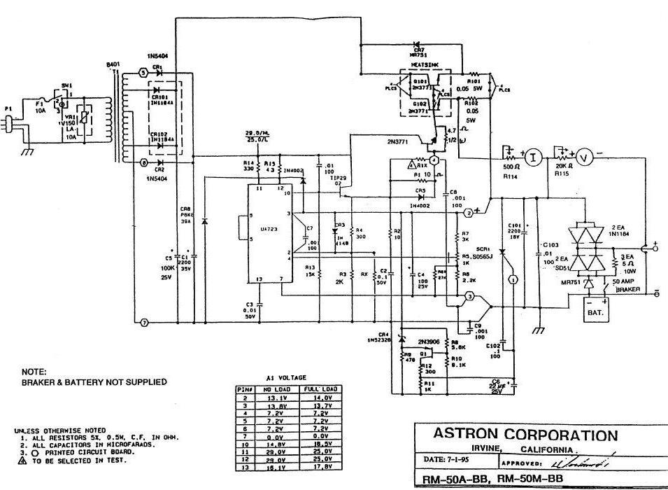
RS-50A, RS-50M, RM-50A, RM-50M 36 KB PDF, dated 03-1996 donated by Tom Allinson WB6DGN
|
|
|
RS-50A, RS-50M, RM-50A, RM-50M 154 KB PDF, dated 01-2013 donated by David Bent
|
|
|
VS-50M 25 KB PDF, dated 08-1982 donated by Bob Shields KA9TYL
|
|
|
VS-50M 74 KB PDF, dated 11-1995 donated by Tim Bovard
|
|
|
RS-50A-BB, RS-50M-BB 127 KB, dated
07-1995 donated by Robert Burton KD4YDC
See the comments above on the battery backup feature.
|
|
|
RS-50M-BB, RM-50M-BB 45 KB PDF, dated
07-2011 donated by Roger Gray N5QS
|
|
|
RM-60A, RM-60M 43 KB PDF, dated
08-1988 donated by Tom Allinson WB6DGN
|
|
|
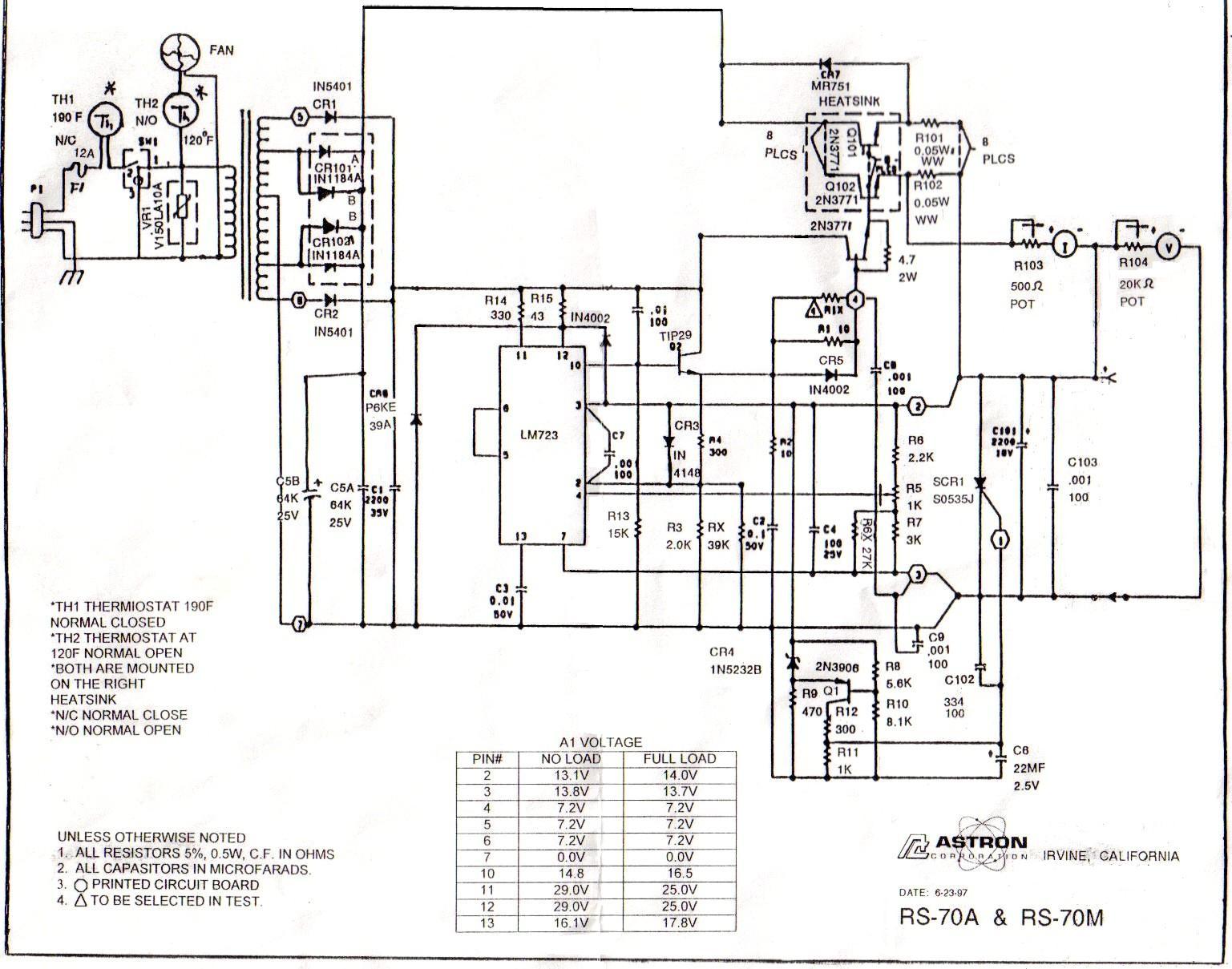
RS-70A, RS-70M 73 KB, unreadable date (probably 08-1988) donated by Mike Morris WA6ILQ
|
|
|
RS-70A, RS-70M Service Manual 1.58 MB PDF, undated, donated by Hugo Loranger VE2UGO
|
|
|
RS-70A, RS-70M 227 KB, dated 06-1997 donated by Avent Lane
|
|
|
RS-70A, RS-70M 74 KB PDF, dated 01-2007 donated by Tom Allinson WB6DGN
|
|
|
VS-70M 54 KB PDF, dated 06-1995 donated by Matt Trull KX4GG
|
|
|
VS-70M 154 KB PDF, dated 04-2020 donated by Hugo Loranger VE2UGO
|
Slim-Line (Low-Profile) Linear Power Supply Schematics:
|
|
SL-11A 99 KB PDF, dated 04-1990
|
|
|
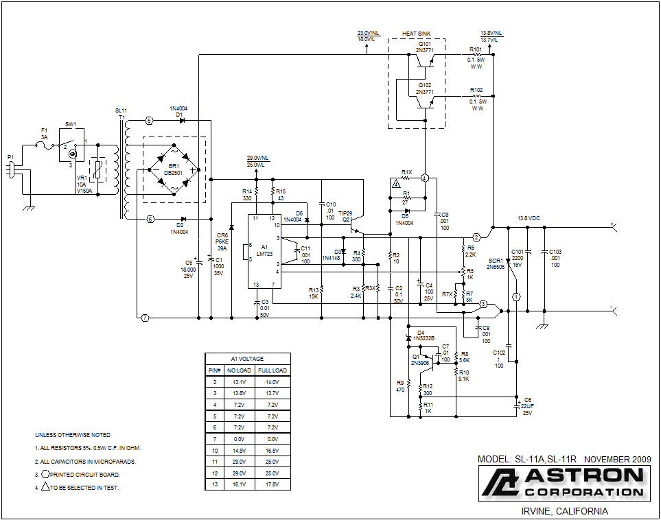
SL-11A, SL-11R 172 KB, dated 11-2009 donated by Paul Mandel W4PGM
|
|
|
SL-15A 120 KB PDF, dated 04-1990 donated by Ed Lambert K1ZOK
|
|
|
SL-15M 42 KB PDF, dated 12-1998
This is also the Motorola HPN9041 that is found in several low power applications including the GR400 rack mount, GR500 wall mount and GR1225 tabletop Repeaters. It can be used with an HLN9455 Battery Revert accessory. More details on the HLN9455, including a manual (with a schematic) can be found on the R1225 page at this web site.
This is one of the very few Astron model numbers that ends in an "M" that is not a metered supply. In this case the M is Motorola.
|
|
|
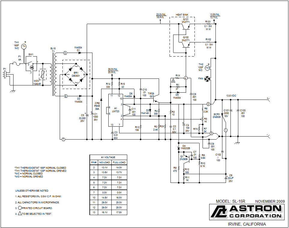
SL-15R 184 KB, dated 11-2009 donated by Dave Christensen KD7UM
|
28 volt Linear Power Supply Schematics:
The Astron factory says that their "28 volt" supplies will adjust down to 22-23 volts (for use with "24 volt" loads).
|
|
LS-25A 28 volt, 25 A intermittent, 18 A continuous, linear power supply 39 KB PDF, dated
04-2004 donated by Astron.
A no-frills 28V power supply similar to the RS-50 supply but with twice the output voltage and half the output current.
This supply, in a rack-mount configuration (LSRM-25A), is also sold under the Uniden name as their model ARX‑330.
|
|
|
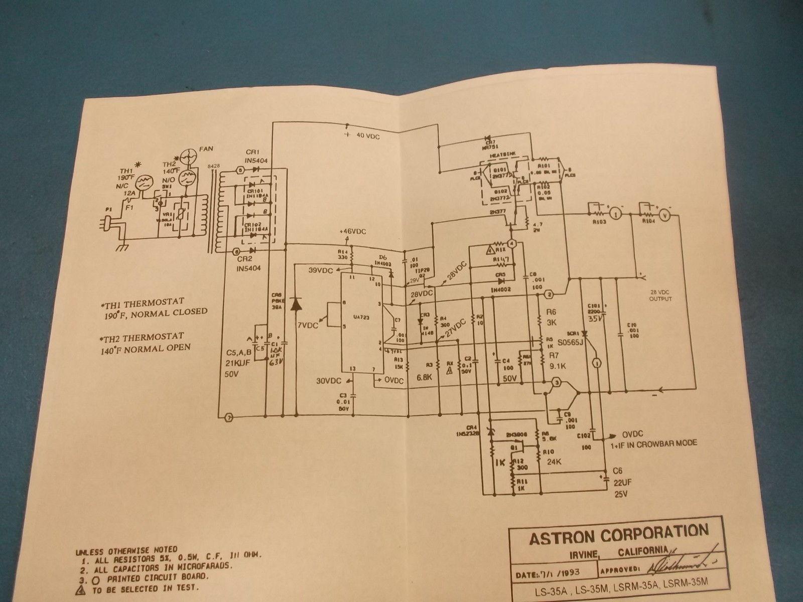
LS-35M 28 volt, 35 A intermittent,
25A continuous, linear power supply 197 KB, dated 07-1993
Found on the web. Has some voltage measurements on it.
|
|
|
VLS-10M 28 volt, 10 A intermittent, 7A
continuous, linear power supply 41 KB PDF, dated 01-1990 donated by Roger
Gray N5QS.
|
|
|
VLS-35M 28 volt, 35 A intermittent, 25 A continuous,
linear power supply 58 KB PDF, dated 06-1995 donated by Ron Vincent KF4D
Similar to the VS-70M supply except for the output voltage (variable from 5 to 32 Volts) and current.
|
|
|
VLS-35M 28 volt, 35 A intermittent, 25 A continuous,
linear power supply 321 KB PDF, dated 04-2016 donated by David Bent.
|
Switching Power Supply Schematics:
|
|
SS-10 4 MB PDF, early 1990s
Schematic plus parts list for SS-10, SS-12 and SS-18.
Not truly accurate, the parts list says that these have a "Banana Socket" for the output.
|
|
|
SS-12 42 KB PDF, dated 08-1996 donated by Eric
Lemmon WB6FLY (SK)
No parts values other than what Eric noted.
|
|
|
SS-18 47 KB PDF, dated 11-1998
|
|
|
SS-25M, SS-30M 483 KB PDF, dated
09-2000
Shows meters and a 120V / 240V input power selection switch.
|
|
|
SS-25M, SS-30M 1.8 MB PDF, dated
09-2000
Schematic plus parts list.
|
|
|
SS-25M, SS-30M 1.7 MB PDF, dated
11-2010
Four pages long, no voltage selector switch, but shows illuminated meters. It also has a
very detailed parts list at the end.
|
|
|
SS-30 71 KB PDF, dated 09-2000 donated by Eric
Lemmon WB6FLY (SK)
There is minimal parts info on the schematic. Further info is available
here.
|
|
|
SS-30 157 KB PDF, dated 09-2000
A second copy of the same schematic, but a little more readable.
|
|
|
SS-25M, SS-30M with enhancements 1.1
MB PDF, dated 09-2000 donated by Alan Sewell N5NA
Alan had to repair a couple of these; in the process he corrected the schematic, added LOTS
of parts values and other notes, and took extensive voltage readings at various points,
complete with photographs. Excellent documentation! It does seem that a meter calibration pot
is missing from the ammeter circuit in the schematic, but since he left no contact info,
this will have to go uncorrected until he sees this and contacts the page maintainer.
Read
his full story here. A local copy can be found here.
|

|
A mod for the Astron SS-25 and SS-30 power supplies (and maybe other SS-series) from NU4G:
(This mod may or may not apply to other models of Astron switching power supplies)
These two power supplies use a simple normally open "click" thermostat to switch a very
noisy (acoustic noise, not RF noise) fan on and off. The fan noise can be annoying at times, so
I've modified my supplies to make it less so. Open the supply after first disconnecting AC power
and allowing for DC voltage to bleed down. Looking inside you will see two sets of heatsinks near
the rear of the unit. Each heatsink has a thermostat attached to it, the left side heatsink has
a normally closed 50 degree C thermostat for the AC input - don't bother it. The right side
heatsink has the fan thermostat mounted to it. The fan thermostat switches DC from the output
to power the fan. If you bridge the thermostat with a two watt resistor of 75 to 100 ohms
the fan will be on continuously, but very slowly. This slow speed is enough to keep the supply
cool with very little noise. Before installing this mod simply running my Icom 756PII HF
station just on receive was enough to turn on the fan every 5 minutes or so. With the mod I've only
had the fan go to full speed (i.e. the thermostat closed) while operating RTTY for an extended time
on a very warm day.
|
Switching Regulated Voltage Converter Schematics: (Also known as DC-to-DC converters)
|
|
1212-18 199 KB PDF donated by Tom Allinson WB6DGN
This unit allows you to use a negative ground +12 volt device (like a two-way radio) in a 12 volt positive ground vehicle (i.e. with a
- 12 volt battery system).
The positive side of the DC input and negative side of the DC output are common.
Another way of saying this is that this is a ground inverting unit.
The schematic shows that it is based on a 556 chip and has a note saying 14 amps continuous duty, 18 amps surge.
|
|
|
2412 49 KB PDF donated by Ed Lambert K1ZOK
This unit is also based on a 556 chip and allows you to use +12 volt devices (like two-way radios)
on +24 volt battery systems where the negative side is common (like those found in many Kenworth,
Peterbilt and other large commercial vehicles such as earthmovers and fire trucks). This schematic does not
have amy notes as to current capacity.
|
|
|
2412-24 V3a Dated 2011 91 KB PDF
donated by Mike Collis WA6SVT. This unit also has a comon negative.
Mike reports: This unit has a "Low Voltage Disconnect" built in but
it's set to drop out at 18 volts. This may work great for an 18-wheeler truck driver wanting
the unit to provide 13.8 volts out on a nearly dead battery, however you might not want
to run your radio site battery down so low, especially at a solar powered site. A slight
modification will raise the dropout point to save a battery bank at a solar site. Simply
change the 62k resistor (R17) on the voltage divider between the input voltage and ground
that supplies voltage to pin 16 (UVLO) of the LM5025B chip. When this pin is below 2.5
volts, the converter shuts down; above 2.5 volts, it turns on. There is hysteresis on
this pin to prevent chattering (about 2 volts difference between off and on). Changing
R17 to 91k will move the Low Loltage Dropout to 22.75 volts and re-connect at just under
25 volts. If you desire an adjustable dropout, add a 30k trim pot to the board in series
with the existing 62k resistor.
|
|
|
2412-12 Rev E 320 KB PDF donated by Tom KN4ONE
Like the other 2412 units above, this unit allows you to use +12 volt devices (like two-way radios) on +24 volt
battery systems that have a common negative. This model uses a TL494 switch-mode regulator IC to do the work.
|
Back to the top of the page
Back to Home
This page originally created in August 2000 by Kevin Custer W3KKC
Totally rewritten and a number of schematics added on 10-14-2004 by Mike Morris WA6ILQ
Copyright © 2000 and and date of last update by Repeater-Builder.com
A large number of people contributed information to this web page, some of whom are no longer with us.
The list became too long to manage.
Several contributions were sent in either anonymously or the person asked not to be identified with a particular submission.
We are grateful to all those who took the time to send us information.
The Astron logo/image is a registered trademark and is used within this page with
permission from the Astron Corporation.
The schematic images are copyright © Astron Corp. Most are dated on the
individual drawing. No copyright infringement is intended. If Astron had the schematic
library on their web site we wouldn't need to.
This web page, the hand-coded HTML on it, this web site, the information presented in
and on its pages and in these modifications and conversions is © Copyrighted 1995
and (date of last update) by Kevin Custer W3KKC and multiple originating authors.
All Rights Reserved, including that of paper and web publication elsewhere.
