Back to Home
Astron Linear Power Supplies
By Robert W. Meister WA1MIK

|
Up one level (Astron index) Back to Home |
Adjusting the Output Voltage of Astron Linear Power Supplies By Robert W. Meister WA1MIK |
|
After getting several emails asking how to do this (I thought it was quite obvious), I finally decided to write something up so the people who know how to search the web and read can find yet another explanation. Amazing; the information is already on the web; there are even videos of the procedure, yet I still had to write an article about it.
Linear Power Supply Styles:
There are basically two styles of Astron linear power supplies:
NOTE: Switching power supplies, whose model numbers start with SS, SRM, SLS, or SLSRM, are NOT covered in this article.
The photos below have been oriented so the component legends on the regulator board are readable. Click on any photo for a larger view.
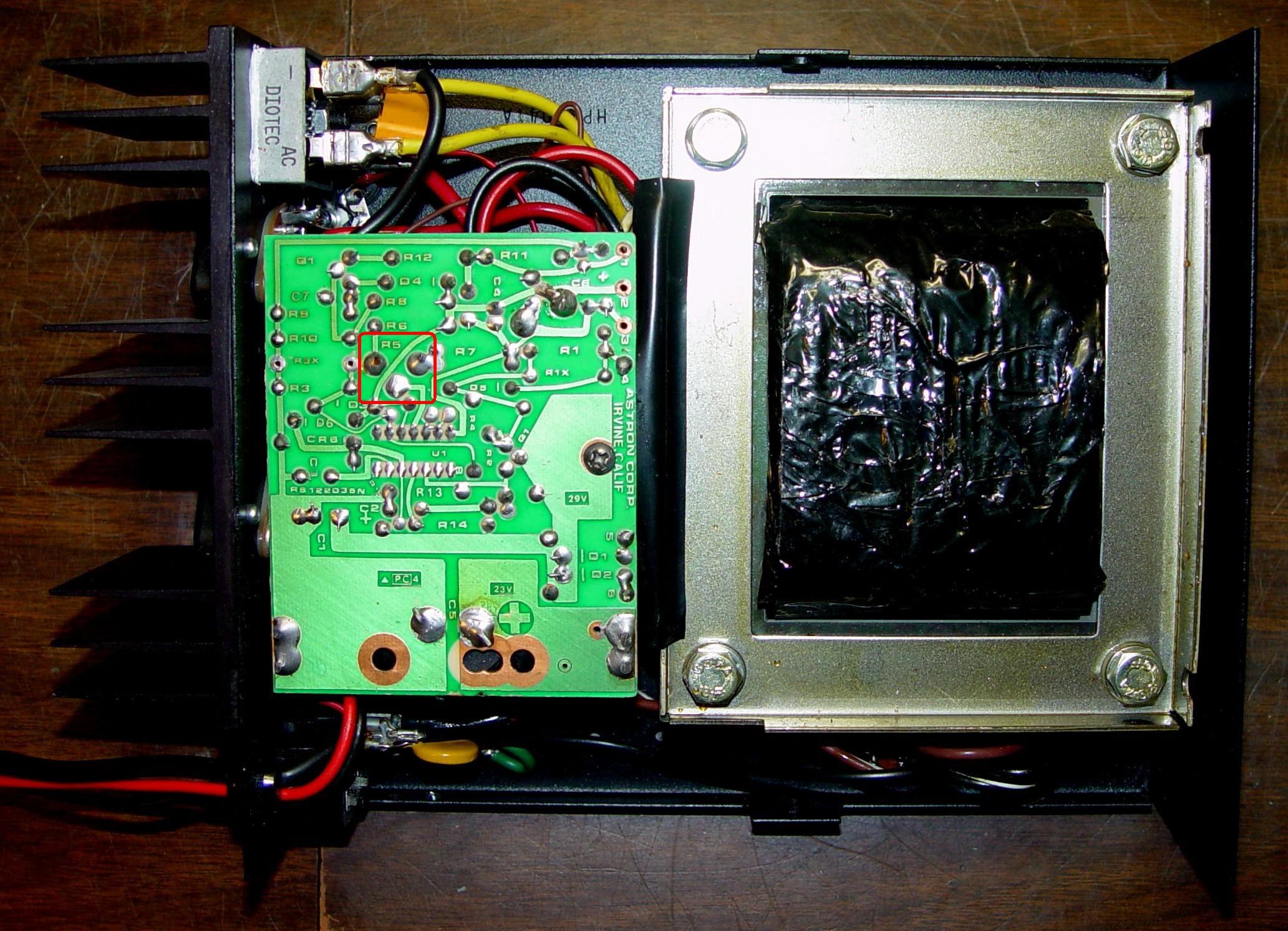
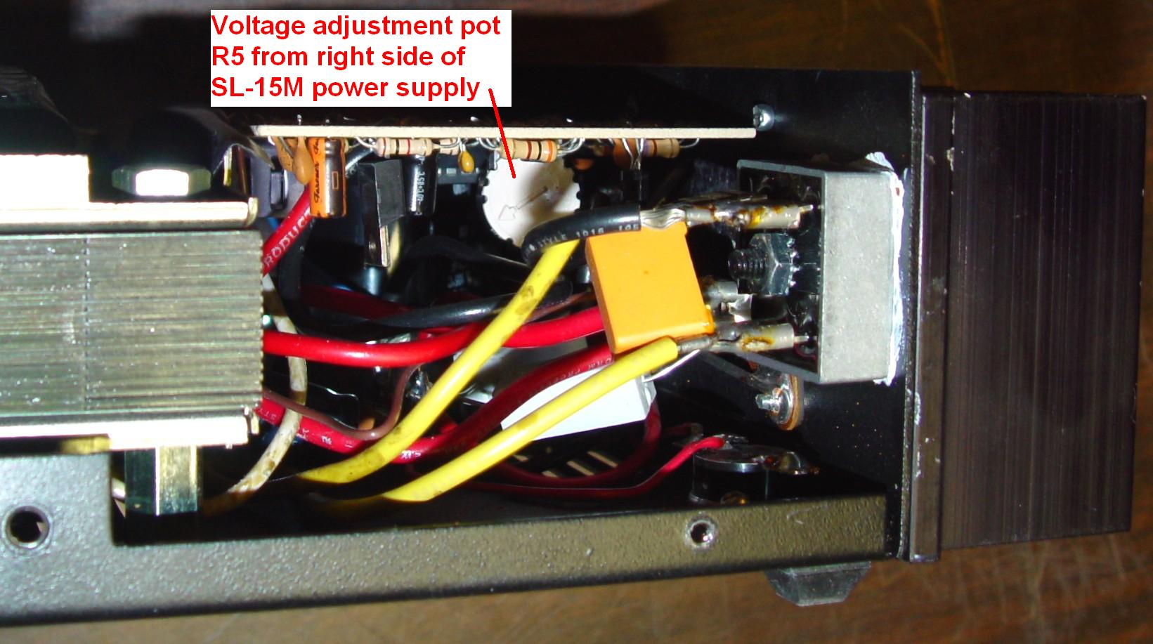
Both styles use the exact same regulator circuit board, which is mounted upside down on top of the main filter capacitor. This means almost all of the components are under the circuit board where you can't see or get to them. On low profile supplies, the main filter capacitor is usually soldered to the regulator board and held to the chassis with a clamp. Here's the inside view of an SL-15M supply. The location of the adjustment pot (R5) has been circled in red. You can really only access the pot from the open end opposite the main filter capacitor.
On the full height supplies, the main filter capacitor can be soldered to the regulator board or held in place with screws that make the electrical connection to the capacitor. In both cases, the capacitor is held to the chassis with a clamp. On the larger supplies, there may be two large capacitors wired in parallel, with the regulator board attached to one of them. Here's the inside view of an RS-35M supply. The location of the adjustment pot (R5) has been circled in red. You can access the pot from the front of the power supply or between the regulator board and the power transformer.
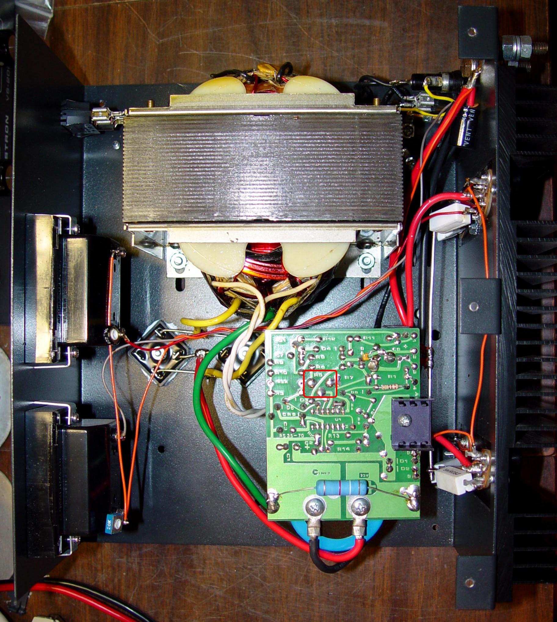
Note the meter adjust pots at the rear of the meters; the voltmeter pot on the lower meter is blue and square and is marked 20K; the ammeter pot on the upper meter is black and round and is marked 1K. The 3.9K 5W resistor soldered to the top of the regulator board above the main filter capacitor is a bleeder resistor that I add to my larger Astron supplies.
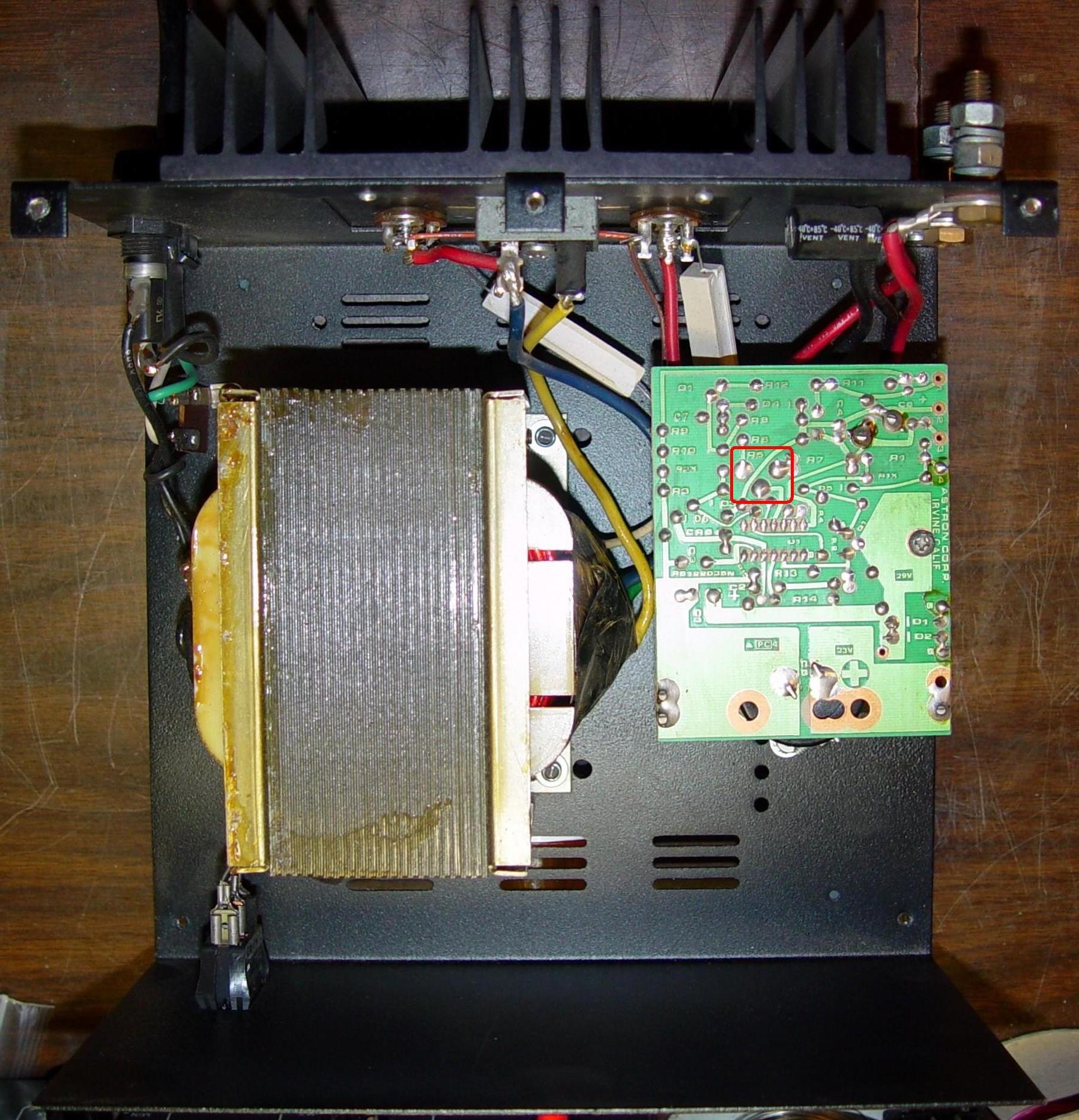
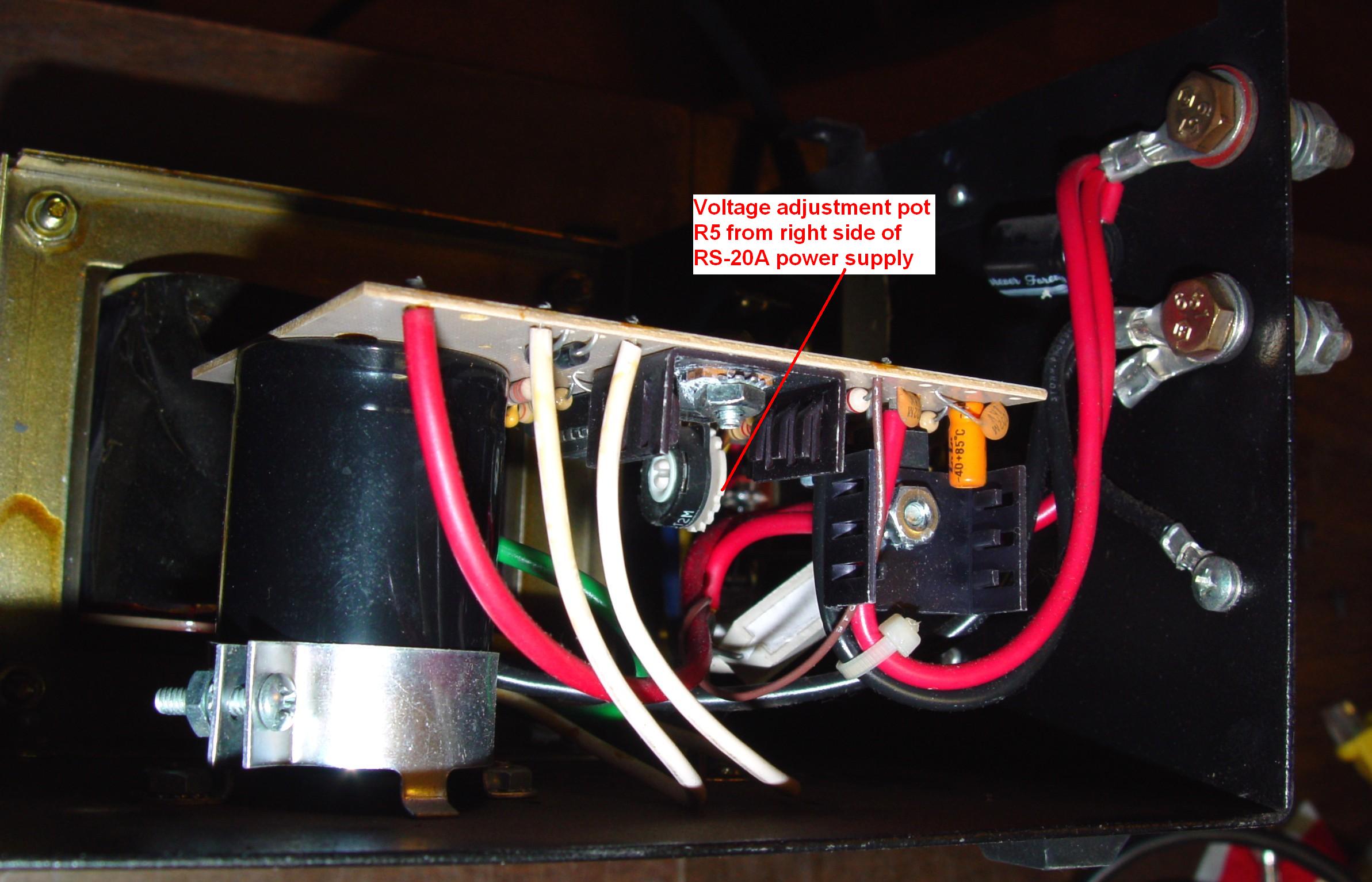
The regulator board is oriented differently on the RS-20A supply, shown below. The location of the adjustment pot (R5) has been circled in red. You can access the pot from any direction EXCEPT the end where the main filter cap is mounted.
Locating the Adjustment Control:
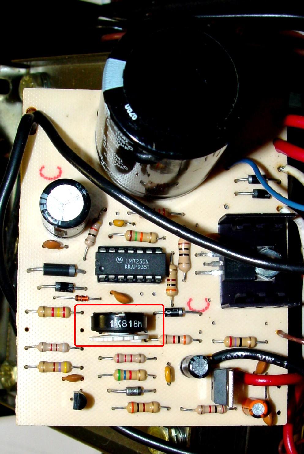
There is only one adjustable component on the regulator board. It is a 1,000 ohm potentiometer labeled R5 on the foil side of the board. It is next to the LM723 regulator IC, on the side where pins 1 through 7 are located, furthest away from the main filter capacitor. All of the components are on the surface of the regulator board that faces downward, so they're not easy to see or get to. For service work, the board is either removed from the capacitor (if it uses screw terminals) or the capacitor's mounting clamp is loosened to allow the board and the capacitor to come out as one assembly. The board can then be flipped over to access the components. The wires attached to the board will restrict its movement, but you should at least be able to get a view of the parts. The potentiometer will be quite obvious in this position. It has been circled in red. Note the value "1K" stenciled in white along the edge. Different style pots have been used depending on what was available.
It's actually quite easy to access the pot just by putting your fingers underneath the board. You can get to the pot from any direction EXCEPT where access is blocked by the chassis or a major power supply component, such as the power transformer or the main filter capacitor. There are no dangerous voltages present under the board but you should avoid the exposed 120VAC primary power input connections and the power switch that are usually located on the other side of the supply.
On most full height supplies, you won't be able to see the pot because of the way the regulator board is oriented in the supply, facing the power transformer. You really are better off feeling for the pot and using one or two fingers to rotate it. You can access it from either side of the regulator board or the end furthest away from the main filter capacitor.
The pot on the RS-20A supply is visible and easily accessed from the right side of the supply, shown here.
You CAN see it quite easily on SL supplies. Here's a photo looking into the open end of the regulator board on an SL-15M supply, from the right side of the supply.
The adjustment pot probably hasn't been turned since the supply was made. These pots can get dirty from lack of use, so when you adjust it, the output voltage may jump around a bit and it might even trip the over-voltage crowbar circuit. You can deal with this by first rotating the pot from end to end several times with the supply turned off, which will clean the dirt out of the pot, then set the pot to its midpoint and continue with the adjustment procedure detailed below.
Adjusting the Output Voltage:
You will need an accurate digital voltmeter to measure the supply's output voltage. Disconnect any load and unplug the power supply. Remove the cover, which is held on with several Phillips screws on the top, sides, and/or underneath, and either lift it straight up or slide it forward or backward off the chassis. The sliding covers are usually a very tight fit and you may have to peel the cover off starting on one side and bending it outward. Connect the voltmeter, set to measure DC Volts, to the output terminals of the supply and plug the supply into the wall outlet. Turn the supply on and allow it to stabilize for a minute or so, then reach under the regulator circuit board and locate the knurled adjustment knob of the potentiometer. Rotate it slowly in one direction or the other while observing the voltmeter. Adjust the pot with your fingers until you get the desired output voltage. No tool is necessary; not all pots have a screwdriver slot in their dials. Clockwise rotation (looking from the accessible end opposite the main filter cap), or rotating the bottom of the dial towards the side of the board where all the wires connect to it, raises the output voltage.
The factory sets the 14V supplies to 13.8V. On most 14V supplies, the adjustment range is roughly between 11 and 15 volts; the adjustment range is roughly between 24 and 32 volts on the 28V units. The factory selects R7X (across R7) to produce the desired maximum voltage. If the voltage goes too high, it may trigger the over-voltage crowbar circuit, which will short out the supply. If that happens, turn the supply off, wait 15 seconds, turn the pot to the midpoint, turn the supply back on, and repeat the adjustment. Don't go as high this time. When you've finished, turn the supply off, unplug the supply, disconnect the voltmeter, and put the cover back on.
On the SL-15M shown in this article, the voltage adjust pot WAS dirty and the unit went into over-voltage protection mode several times. I did have to clean the pot by rotating it back and forth from end to end a few times. After I did that, the adjustment range was measured as 11.374V to 14.966V; I set the supply for 13.80V.
Other Items:
For VS and VLS supplies with front panel voltage adjustment pots, set the front panel pot to the maximum voltage and adjust the internal pot (R5) for 15V (or 32V for the VLS supplies) output.
While you've got the supply open, you should adjust the pot on the back of the front panel DC Voltmeter, if present, so it agrees with the digital voltmeter. You can see this pot on the photo of the full-height RS-35M supply above. On some supplies with just a single Volt/Amp meter, the pot may be located elsewhere.
Contact Information:
The author can be contacted at: his-callsign [ at ] comcast [ dot ] net.
Back to the top of the page
Up one level (Astron index)
Back to Home
This page originally composed on 14-Nov-2017
Article text, layout, photos, and hand-coded HTML © Copyright 2017 and date of last update by Robert W. Meister.
This web page, this web site, the information presented in and on its pages and in these modifications and conversions is © Copyrighted 1995 and (date of last update) by Kevin Custer W3KKC and multiple originating authors. All Rights Reserved, including that of paper and web publication elsewhere.