Back to Home
Current Adjustments to
Astron Linear Power Supplies
By Robert W. Meister WA1MIK

|
Up one level (Astron index) Back to Home |
Adding Variable Voltage and Current Adjustments to Astron Linear Power Supplies By Robert W. Meister WA1MIK |
|
Astron sells fixed (RS, RM series) and adjustable (VS, VM series) 14 volt linear power supplies, with and without meters. This article tells you how to convert a fixed supply to an adjustable supply. There's no reason why you can't make the same modification to a 28 volt supply; Astron uses the same part values; I just haven't tested it. They also sell the SL series, which use the same regulator, but the cases just don't have the room to mount one or two pots.
All Astron linear power supplies have an internal voltage adjustment pot located on the regulator circuit board. If your supply isn't putting out the voltage you want, open the case and adjust the pot until it does. The limit is usually around 15V. If you go too high the crowbar protection circuit will fire and short out the supply, sometimes blowing the fuse. You only need to add front panel adjustment pots if you want to conveniently and frequently lower the voltage or current limit. The internal pot always sets the maximum output voltage.
I've based this modification on the 14 volt 35 amp power supply because it's one of the most popular models, comes in all varieties, and there are plenty of schematics available for it. The primary difference among the various supplies is the number of series-pass transistors mounted on the heat sink.
Cautionary Note:
Astron's fixed-voltage supplies can put out the rated current at the rated voltage. If you reduce the output voltage, the series-pass transistors on the heat sinks will dissipate more power and you could exceed their ratings. For example, with a raw DC voltage of 22 volts and a regulated output voltage of 14 volts, the series-pass transistors are dropping 8 volts. At 30 amps, that's 240 watts. If you reduce the regulated output voltage to 7 volts, the transistors are now dropping 15 volts. At 30 amps, that's 450 watts, almost twice the power. That's a lot of heat; neither the transistors nor the heat sink are capable of dissipating that much power. If you reduce the output voltage, you must also reduce the current used by the load.
Background Information and Suggestions:
Astron uses 2.5K linear-taper carbon composition potentiometers with 1/4 inch diameter shafts and 3/8 inch bushings, similar to Mouser part "RV24AF-10-15R1-B2.5K-3" that costs about $1.55US. There really is no reason I can think of why you can't use a much more popular 2K or 5K part. You can choose carbon composition, cermet, or plastic, 6mm, 1/8 or 1/4-inch shaft (your choice). Choose knobs that fit the pot shaft. The power requirements are minimal; a 1/2 or higher Watt pot would do fine. Use Ohm's Law to figure out the maximum power dissipation of the current adjustment pot, as it has to dissipate the full power supply output voltage. Wiring is not critical either; I used #22 stranded wire. Just leave enough slack to allow you to remove the regulator board for service when necessary.
You can implement adjustable voltage, adjustable current, or both. Pick the one(s) you want or need. If your supply has two meters, put the voltage adjust pot under the voltmeter and the current adjust pot under the ammeter. If it has just one meter, flip a coin and decide where to put the pots. On supplies large enough to have two meters, Astron puts the voltmeter and the voltage adjustment pot on the right.
You may want to remove the regulator board from the main filter capacitor (if it uses screw terminals) or loosen the clamp around the main filter capacitor (if it's soldered to the board) and flip the board up to access the component side. You can solder the wires to either side of the board, but if you want to make it look neat, run the wires into the holes in the solder pads from the component side. I don't know how Astron does it, but after seeing the insides of many of their power supplies, I'm sure they do it the quickest and least expensive way possible.
Here's a nice schematic diagram of a 2000-vintage RS-35M power supply that was drawn by K2QDE and sent to repeater-builder.
Here's the same schematic modified to be a VS-35M with the addition of the V-Adj (to the left of the LM723 regulator) and I-Adj pots (below and to the right of the LM723 regulator).
Voltage Adjustment Modification:
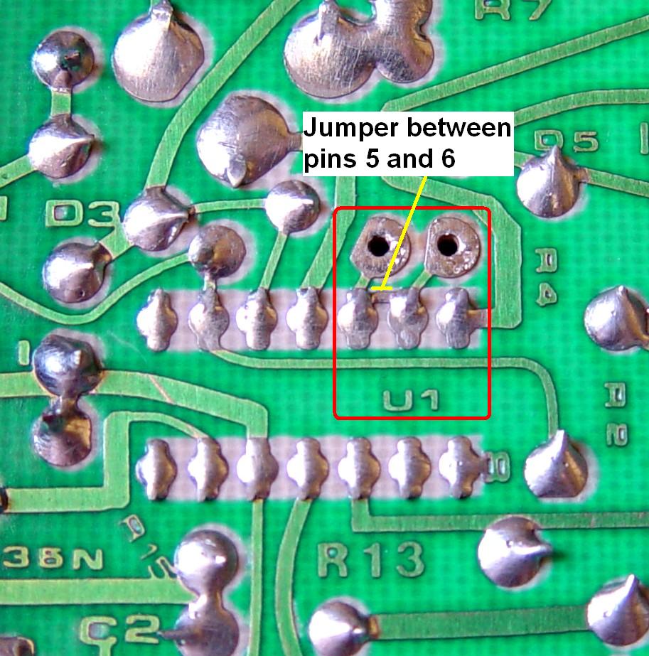
The stock supply has a foil jumper that connects the LM723 regulator IC (U1) pin 5 (the non-inverting input to the voltage comparator) to pin 6 (the reference voltage output). The power supply's output voltage is adjusted by R5, the small 1K pot located on the circuit board that goes to pin 4 (the inverting input to the voltage comparator).
To make the power supply adjustable, you first need to break the connection between pin 5 and pin 6. You will have to cut the small foil jumper the pads next to pin 5 and pin 6. I just used a small pocket knife to slice through the foil next to the two IC solder pads, then dug the remaining foil off the board. I verified that the connection was truly open with an ohmmeter. The photo below shows U1 pins 5, 6, and 7 in the red box, with a yellow line pointing to the foil connection between pin 5 and pin 6 that you need to cut. It also shows the two solder pads you can use to connect the new pot to, at pin 5 and pin 6. Click on the photo for a larger image.
Add a pot that varies the voltage on pin 5 between the maximum available from pin 6, to a minimum possible from ground. This pot will adjust the output voltage to any value between a few volts and the maximum set by R5. When the pot is turned fully CCW, pin 5 is connected to ground and the minimum output voltage of a few volts is obtained. When the pot is turned fully CW, pin 5 is connected to pin 6 and the maximum output voltage is set with R5, as stated in an earlier paragraph.
The new pot is wired as follows.
To properly set the power supply voltage, turn the new pot fully CW and adjust R5 on the regulator board to 15.0VDC. Don't go higher than that because you'll likely trip the over-voltage protection (crowbar) circuit.
The LM723 can supply a maximum of 15 milliamps on pin 6. With about 7.2 volts available, the lowest value pot you can use to adjust the voltage is about 500 ohms. Astron probably chose a 2.5K part because it worked well for the current adjustment and it was appropriate for the voltage adjustment as well. You could use anything from 1K to 10K ohms for the front panel voltage adjustment.
This modification can easily be reversed by removing the pot and adding a jumper in the two solder pad holes going to the LM723 pin 5 and pin 6, and resetting the output voltage to 13.8-14.0VDC.
Current Adjustment Modification:
The stock supply has its maximum current limit set via R3 and R3X. Astron selects both when they manufacture the power supply, and the values depend on the current they feel the supply is capable of safely providing, usually a few amps greater than the maximum according to the model number. My RS-35M had a 2.4K resistor for R3 and did not have anything installed for R3X.
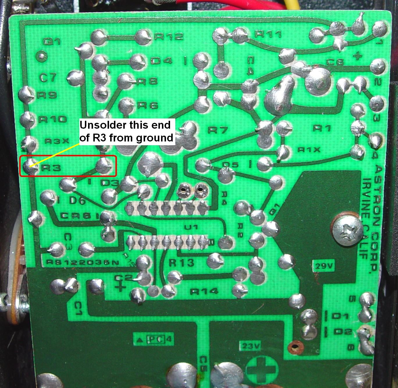
To make the power supply adjustable, unsolder just the ground end of R3 and lift the lead out of the hole. When the lifted end of R3 is grounded, the supply will generate maximum current. The new pot will move the lifted end of R3 between ground (maximum current) and the supply's positive output (minimum current). The photo of the board below shows the location of R3. The left side is the ground end you need to unsolder. Click on the photo for a larger image.
The new pot is wired as follows.
There is no adjustment for the maximum current; you'll get whatever Astron thinks you should have when the new pot is turned fully CW. The minimum current depends on the value of the pot you use.
It seems that Astron also adds a 10uF 50V electrolytic capacitor in series with a 1.5K resistor across R3X, a resistor which is "selected at test" to trim the maximum current. This RC network is not documented on any of the variable power supply schematics (mine worked fine without it) but I added it to my PDF file (above). When you insert a pot into the ground end of R3, the value of R3X may determine the minimum current limit. You may also have to reduce the value of R3 just a bit (measure R3X and add a similar resistor in parallel with R3) to give you the same maximum current you had originally.
You can easily reverse this modification by removing the pot and soldering the free end of R3 back into its original ground hole.
Results:
I performed each modification separately on a 2002-vintage RS-35M as detailed above. The supply was initially set to output 14.000VDC and the front panel meter indicated 14.0V with no load.
The voltage adjust pot smoothly varied the output voltage between 14.00V (fully clockwise) down to 1.50V (fully counter-clockwise) however the supply takes a few seconds to reduce its output voltage due to the filter capacitor across the output terminals. It would change much faster with any sort of load attached.
The current adjust pot was quite non-linear, but this is to be expected when using a linear potentiometer. A slight rotation from fully clockwise was all that the supply needed to go into current limiting with a 0.5 ohm (28A) load, but that's how they work. Once the supply went into current limiting, the output voltage was reduced to about 4V and the output current was reduced to about 8A. Once I removed the load, the output voltage immediately rose to 14.0V.
Using Different Pot Values:
I purchased 1K, 2K, 2.5K and 5K linear carbon composition pots for about $1.60US each. All worked for both voltage and current adjustments, smoothly varying the output voltage between 1.5V and 14.0V (the voltage set by R3 without the pot), however the 1K pot had slightly lower output voltage at each end of the pot, and I would not recommend it. I suspect it was loading down the V-REF pin slightly.
All of the pots worked fine for the current adjust. When turned down, the supply would go into current limiting or fold-back with the two loads I tried: 0.5 ohm and 1.0 ohm. It really depends on how much range you want on the pot. For example, with a 1K pot set about half way, the supply folded back with a 14A load. I didn't have sufficient loads to discover the minimum current value.
Contact Information:
The author can be contacted at: his-callsign [ at ] comcast [ dot ] net.
Back to the top of the page
Up one level (Astron index)
Back to Home
This article initiated on 13-Apr-14 and first posted on 28-Apr-14.
Photos, layout, and hand-coded HTML © Copyright 2014 and date of last update by Robert W. Meister.
Pictorial diagram © Copyright 2014 by Bob McKinlay VE3DJ.
This web page, this web site, the information presented in and on its pages and in these modifications and conversions is © Copyrighted 1995 and (date of last update) by Kevin Custer W3KKC and multiple originating authors. All Rights Reserved, including that of paper and web publication elsewhere.