Back to Home
Linear Power Supplies
By Robert W. Meister WA1MIK

|
Up one level (Astron index) Back to Home |
Paralleling Two Astron Linear Power Supplies By Robert W. Meister WA1MIK |
|
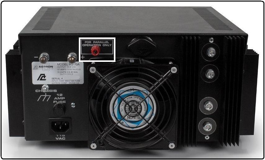
I have noticed on the larger supplies, such as the 14 Volt RS70 and the 28 Volt LS35, there's a red binding post terminal on the rear that's labeled "FOR PARALLEL OPERATION ONLY". None of the schematic diagrams ever showed such a connection and it's been a mystery to me for quite some time. Well, the mystery is finally solved, thanks to a reader who needed help repairing an RS70M supply.
This terminal is only present on the highest-current, non-adjustable power supplies, those capable of 50 to 70 Amps at 14V, or 30 or more Amps at 28V. If you have a supply rated at a lower current and need more current capability, Astron would prefer you to buy a higher current supply and not parallel them. If you need more current than their single highest-current supply can put out, then you would need to parallel two of them. It's entirely possible you could parallel more than two but I wouldn't recommend that. Buy a supply meant to handle the desired current.
Here's a photo of the rear of an Astron RS-70A showing the binding post terminal. On some supplies this terminal may be located higher up, in the "expansion" area.
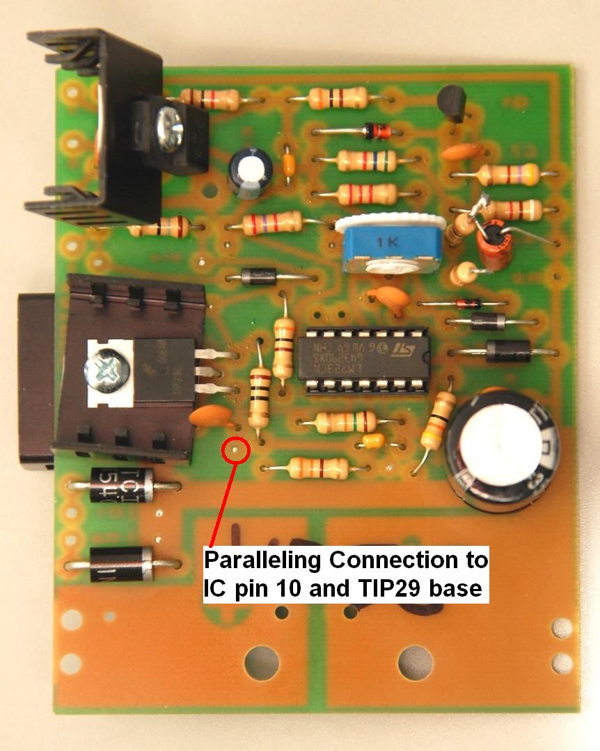
This terminal is wired directly to the LM723 regulator IC pin 10, which feeds regulated drive power to the TIP29 driver transistor on the regulator circuit board. There's an unused solder pad reserved just for that wire. See the photo below of a recent regulator board component side. Click on the image for a larger view.
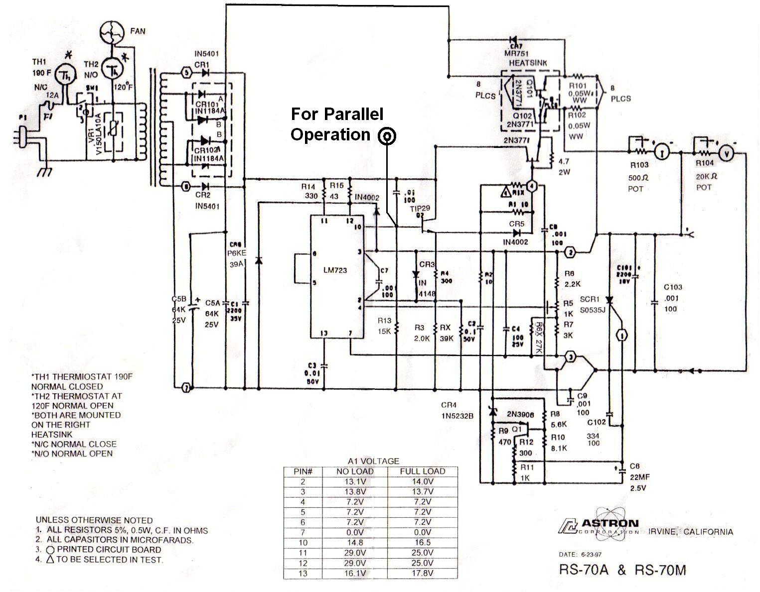
I've marked up an RS70M schematic showing the connection for the parallel binding post. Click on the image for a larger view.
So, how do you physically connect two supplies in parallel? It's not difficult.
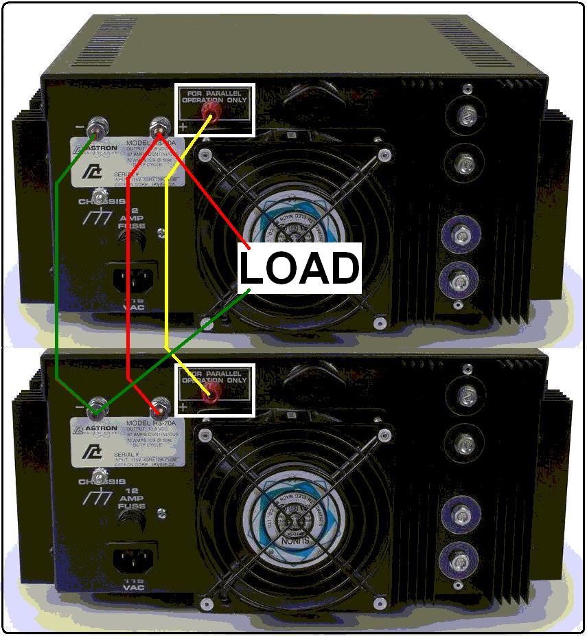
Remember that each power supply is capable of drawing 12A from the AC line, so you probably want to run each supply from its own dedicated 15A or 20A circuit with nothing else plugged into either one.
Contact Information:
The author can be contacted at: his-callsign [ at ] comcast [ dot ] net.
Back to the top of the page
Up one level (Astron index)
Back to Home
This page originally composed on 10-Oct-2016
Layout hand-coded HTML © Copyright 2016 and date of last update by Robert W. Meister.
This web page, this web site, the information presented in and on its pages and in these modifications and conversions is © Copyrighted 1995 and (date of last update) by Kevin Custer W3KKC and multiple originating authors. All Rights Reserved, including that of paper and web publication elsewhere.