Back to Astron Index
Back to Home
Astron Linear Power Supplies
By Robert W. Meister WA1MIK

|
Back to Astron Repair Back to Astron Index Back to Home |
LM723 Regulator Operation in Astron Linear Power Supplies By Robert W. Meister WA1MIK |
|
The LM723 voltage regulator IC is the central control unit in many linear power supplies including the Astron 14 and 28 volt units. Because this IC is socketed and inexpensive, many people just replace it when their supply does strange things, but it is not always bad. Once you know how it's supposed to work, you can check its operation in the supply to verify that it is doing what it's designed to do.
There are four basic functional blocks in the LM723, and each will be discussed separately.
The LM723 14-pin Dual In-line Package has the following pin assignments.
| Signal Name | Pin | Pin | Signal Name | |
|---|---|---|---|---|
| N/C | 1 | 14 | N/C | |
| Current Limit | 2 | 13 | Compensation | |
| Current Sense | 3 | 12 | Vcc | |
| Inverting Input | 4 | 11 | Vc | |
| Non-Inv. Input | 5 | 10 | Vout | |
| Vref | 6 | 9 | Vz | |
| Ground | 7 | 8 | N/C |
Here's a representative schematic of the LM723, MC1723, uA723, etc.
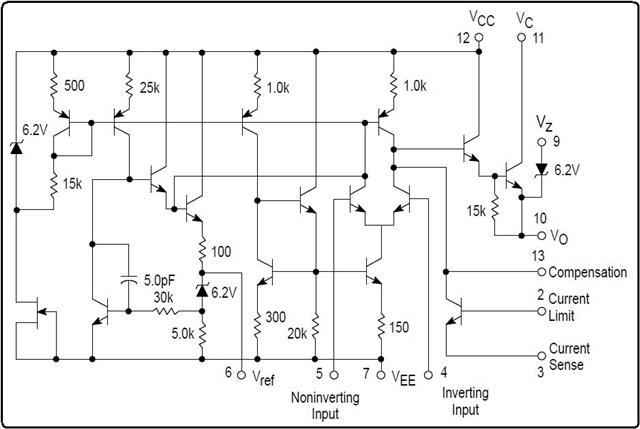
Now let's look at the various circuit areas.
Op-amp Comparator (pins 4 and 5):
The operational amplifier or comparator looks at the voltages on pins 4 and 5. Pin 4 is connected to the arm of the voltage adjust pot (R5) to provide a sample of the actual supply output voltage. Pin 5 is usually connected to the reference voltage at pin 6, which is about 7.15 Volts. When the voltage on pin 4 is lower than the voltage on pin 5, the output transistor will supply current to the external components (TIP29 and series-pass transistors on the heat sink) connected to pin 10 in an attempt to raise the supply's output voltage, and hence the voltage on pin 4, which will bring pin 4 back to the same voltage as pin 5. Conversely, if the voltage on pin 4 is higher than the voltage on pin 5, the output transistor will turn off and let the supply's output voltage reduce itself, thus lowering the voltage on pin 4, which will bring pin 4 back to the same voltage as pin 5. This action can happen at a very rapid rate but other parts around the IC smooth out these changes. The IC is constantly trying to maintain equilibrium of the voltages at pins 4 and 5.
Regulated Reference Voltage Supply (pin 6):
Pin 6 provides a 6.8 to 7.5 Volt (7.15 Volt nominal) well-regulated reference voltage. In Astron supplies without a front-panel voltage adjustment pot, pin 6 is connected to pin 5, one input of the op-amp comparator, with a very thin foil trace. On variable supplies (VS and VLS, with or without meters), the top of the voltage adjust pot goes to pin 6, the arm of the pot goes to pin 5 to provide a variable reference voltage, and the bottom of the pot goes to ground. The output voltage thus follows some ratio of the voltage on pin 5, letting you alter the supply's output voltage from the maximum (set by R5, the pot that provides voltage to pin 4) to a minimum of about 2.0 Volts.
Output Transistor (pin 10):
The output of the IC is the emitter of an NPN transistor at pin 10. This can supply about 150 milliAmps of current to a load or to other current-boosting components. In Astron supplies, this feeds the TIP29 transistor on the regulator board, which feeds the series-pass transistors on the heat sink. Note that pin 10 can only supply current to the load by pulling it up to the voltage supplied on pin 11; it can't pull pin 10 down to ground. External components attached to this pin (the load or resistors elsewhere on the regulator board in Astron supplies) pull it down. Anything connected to pin 10 that can supply current to the load can easily over-ride the IC and prevent proper operation of the supply, usually showing up as uncontrolled or high output voltage. This includes a leaky TIP29 or the components around it.
Current-Limiting Components (pins 2 and 3):
The IC can sense the output current by monitoring the voltage drop across a resistor connected between pins 2 and 3. When the drop exceeds about 0.7 Volts, the current is deemed to be excessive and the output transistor's drive is restricted, preventing it from turning on further. This limits the output current going to the load. A lower resistance value increases the current limit value.
Power Supplies (pins 7, 11 and 12):
The main IC gets its power from pin 12. The output transistor gets its power from pin 11. While these can be connected together, often pin 12 is regulated better and protected from incoming transients. Pin 7 is circuit ground.
Other Signals (pins 9 and 13):
Pin 9 goes to a Zener diode. Some configurations, such as negative and switching supplies, make use of it. This pin is not utilized in Astron supplies.
Pin 13 is labeled "Compensation" and it provides a way to stabilize the comparator output to prevent oscillation. This pin can be grounded to shut off the regulator output. Usually a small value capacitor is connected here; in Astron supplies it is typically 0.01uF although it can range from 0.001uF to 0.1uF.
Differences from NE550 IC:
The NE550 voltage regulator was used in VHF Engineering power supplies. It is the same as the 723 regulators EXCEPT the reference voltage on pin 6 is 1.53 to 1.73 (nominally 1.63) Volts. The two ICs are, in all other respects, identical. You can swap the ICs but you'll have to modify the voltage adjustment resistors to accommodate the different reference voltage. There's an article in the VHF Engineering section of this web site that shows what to change.
Contact Information:
The author can be contacted at: his-callsign [ at ] comcast [ dot ] net.
Back to the top of the page
Back to Astron Repair
Back to Astron Index
Back to Home
This page originally composed on 11-Jun-2017
Text, layout, and hand-coded HTML © Copyright 2017 and date of last update by Robert W. Meister.
This web page, this web site, the information presented in and on its pages and in these modifications and conversions is © Copyrighted 1995 and (date of last update) by Kevin Custer W3KKC and multiple originating authors. All Rights Reserved, including that of paper and web publication elsewhere.