Back to Home
Linear Power Supplies
By Robert W. Meister WA1MIK

|
Up one level (Astron index) Back to Home |
Repairing Astron 13.8V Linear Power Supplies By Robert W. Meister WA1MIK |
|
This article is based on my personal experience fixing these supplies. I also solicited and received input from other people who have experienced the joys of "fixing it yourself." The applicable model numbers start with RS, VS, RM, VM, and SL.
There is a lot of helpful information in this article. Some may only be a few words long, but it is all very important, and many useful hints, clues, and tidbits will be found if you read it a few times. The most common issues will be covered. It's up to you to test every component, which may include unsoldering one or both leads of each part to do so. Trying to measure some resistors while installed in the supply may lead to inaccurate readings.
Note that most of the theory and techniques in this article also apply to the Astron 28 volt linear supplies (LS and VLS series), as well as many 13.8-volt linear supplies made by other manufacturers (Pyramid, for example). Switching power supplies (those whose model numbers start with "SS") have their own issues that will not be covered in this article.
Failures usually happen for a reason, but they can generally be isolated to a problem with the incoming power (a nearby lightning strike, 240 volts AC applied instead of 120 volts AC, a surge due to generator operation, etc.) or a problem caused by the load (a short circuit or too much current being drawn). Also be aware that a lightning strike can cause some components to act in ways you would never expect, or cause multiple failures, which can mislead you into replacing parts that may not be bad, or not believing some of the measurements you make. Think about how things are supposed to work then try to find out why they aren't working that way.
Health and Safety Warnings:
During the troubleshooting process, you will be measuring voltages with the power supply cover off and 120 volts AC applied. Be very careful around the AC stuff: the incoming power cord or receptacle, the fuse holder, and the power switch. Lethal voltages are present. Be careful.
Before doing repair work on the regulator board or any of the DC circuitry, make sure the AC power is turned off and disconnect the AC line cord, then discharge the main filter capacitor(s) using a 30-300 ohm 2 watt resistor. Attach it to the capacitor's leads and leave it there for 5-15 seconds. There is no bleeder resistor in any of the Astron power supplies (unless you add one yourself).
This article assumes that the reader is familiar with simple AC and DC circuits and most electronic components and knows how to use a voltmeter and an ohmmeter.
Parts can fail in odd ways. Multiple part failures are rare but they can happen. I can't predict, explain, or suggest repairs for every problem that can crop up. I've done my best to provide a methodical way of bringing life back to many supplies. Divide and conquer. Disconnect or remove parts to make sure the expected results actually happen. For example, removing the LM723 regulator IC from it's socket should let the output voltage go to zero volts.
General Linear Power Supply Theory:
Astron linear supplies rely on a high current, filtered, unregulated raw source of DC power, created by a large, heavy transformer, some diodes (either discrete stud rectifiers or diode bridges), and one or two filter capacitors. This creates about 22 to 24 volts DC that will drop down to about 18 volts DC under full load. This raw supply is followed by one to eight transistors that provide current to the load. Because these transistors are in series with the load, they're often called series-pass transistors. The output voltage is sensed by circuitry on the regulator board and a control signal is sent to these transistors to maintain a constant output voltage as the load changes. An over-voltage circuit will activate if the output voltage goes too high, and it will apply a short circuit to the output terminals, which will shut down the power supply, causing it to get hot. This may or may not cause the AC fuse to blow. Finally, optional voltage and current metering and/or adjustment pots may be present on the front of the unit. Schematics for most of the models are on-line, but you may have to view a few different ones to find information about meters and front panel adjustment pots.
There are a couple of articles in the Astron section of Repeater-Builder about linear power supplies in general, and Astron power supplies in particular. These would be useful to read. This article details the operation of the LM723 regulator IC.
Major Circuit Variations:
The transformers may or may not have a center-tap on the secondary winding. Usually the RS-series supplies have the center tap, while the SL-series do not. If there's a center-tap lead, it goes to ground and there will be two stud diodes or one or two bridge rectifier packs with only the positive and AC terminals connected. If there is NO center-tap lead, a bridge rectifier will be used with all four terminals connected and the negative terminal goes to ground. Don't confuse the two. I've seen people try grounding the negative terminal of the bridge rectifiers on supplies with a center-tap, with disastrous results.
Some of the older supplies had either the over-voltage SCR or the TIP29 driver transistor mounted to the chassis. Luckily Astron has moved all these parts to the regulator board on supplies manufactured over the last 15 years or so. The latest boards also have one or two small finned heat sinks on each side of the circuit board to help cool the TIP29 driver transistor, and often another small heat sink mounted to the SCR.
Incoming Power Problems:
Excessive input voltage may, on rare occasions, destroy the transformer's primary winding. I haven't seen this happen but it is possible. There is a surge protector device across the primary winding that looks like a black or red dipped disc capacitor. This may also be destroyed and it could open or short out. The primary winding's DC resistance is usually very low, under 1 ohm but not zero ohms.
Many voltage spikes, particularly surges due to lightning, will go right through the power transformer and hit the rectifiers. The diodes may short or open, or both. A shorted diode will cause the AC fuse to blow immediately and repeated attempts may also cause the filter capacitors to bulge or even explode. See this article for a list of the various AC line fuse values. Rarely will anything further down the line be affected. There are also two discrete diodes and a 1000uF capacitor on the regulator board that can short or open or vent through its top. CR6 on the regulator board is a Transient Voltage Suppressor (TVS) that acts like a voltage clamp and should only have an effect when the regulator board's DC voltage exceeds about 35 volts DC. Under normal circumstances, the voltage across the TVS should be about 29 volts DC; you can see these voltages on most Astron schematic diagrams by looking at pin 12 of the LM723 regulator chip. If the voltage spike was excessive, the TVS may turn into a low-value resistor in an attempt to prevent further damage. This will reduce the supply voltage to the LM723 and the supply won't work properly.
Most incoming power problems usually stop at the regulator IC, so look for defective parts that, on the schematic diagram, are to the left of the LM723.
If the supply is producing the proper DC voltage but there is hum on the output, the most common problems are the rectifiers or the main filter capacitor that form the raw DC supply.
If the supply voltage is coming up very slowly and not providing much or any load current, check the main diodes or bridge rectifiers. The voltage across the main filter capacitor should come up instantly to around 24VDC.
Load-related Problems:
If the load current is excessive or ventilation is blocked, the series-pass transistors on the heat sink could overheat and fail. If they open, you'll find that the supply will no longer be able to maintain the regulated output voltage with full load. If they short out, they'll send raw unregulated voltage to the load. The crowbar circuit will detect the over-voltage condition and it should fire, shorting the output voltage to under 1V and probably blowing the AC fuse. If the crowbar fires and the fuse does not blow the pass transistors will get very HOT.
If the supply is putting out 22-24V all the time, one or more of the series-pass transistors or the driver transistor is shorted out. This includes a TO-3 driver transistor mounted on the rear panel of the larger supplies. Usually the crowbar circuit will fire to protect the load but they've been known to go bad. If the crowbar fires and the fuse does not blow the pass transistors will get very HOT.
There's a TIP29 driver transistor on the regulator board. This can also open or short, but rarely seems to do so. If all of the series-pass transistors open, the TIP29 might still provide an amp or so to the load. Some older supplies remote-mounted this transistor on the bottom of the chassis.
If the load current is too high, the supply should go into current limiting, however not all Astron supplies do this well. There are usually some components whose values are "selected at test" to adjust the point at which current limiting occurs. Some people feel that this should happen at twice the "rated" current of the supply, however Astron linear supplies have two current ratings: the maximum Intermittent Commercial and Amateur Service (ICAS) current and the maximum Continuous Commercial Service (CCS) current. The digits in the supply's model number specify the ICAS current, i.e. an RS35 is rated for 35 amps ICAS. The CCS rating is usually around 60 to 70% of the ICAS rating, so the same RS35 is good for about 25 to 28 amps continuously, with adequate ventilation, which usually means a fan added to the heat sink. So should the current limiting occur at 70 amps (twice the ICAS rating) or at 50 amps (twice the CCS rating)? You'll get a different answer from each person you ask.
If the supply produces the proper DC voltage with no load, but drops a bit with a normal load and/or there is hum on the output, the most common problems are an open diode in the rectifiers or the main filter capacitor that form the raw DC supply. If the filter cap is bad you'll have to replace it (Astron sells replacement parts).
If the output voltage drops to below 1 volt when a load is attached, check the disc capacitor on the regulator IC, pin 13 (or just replace it). If this is leaky or shorted, weird things can happen.
If the output voltage is coming up very slowly and not providing much or any load current, check the main diodes or bridge rectifiers. The voltage across the main filter capacitor should come up instantly to around 24VDC. Sometimes "open" diodes leak enough current to allow the main filter capacitor to charge but they won't provide any load current.
Miscellaneous Problems:
If the supply is putting out proper DC voltage under some load but the front panel ammeter doesn't show any current, one of the series-pass transistors could be open. The ammeter actually measures the voltage drop across one of the 0.1 or 0.05 ohm emitter-balancing resistors; if there's no current, there's no meter indication. If that transistor shorts out and/or its emitter-balancing resistor opens, the ammeter will have excessive current flow through it and will most likely burn out. The calibrating potentiometer in series with the meter could also be open. Replacing either component is your only cure.
If the pass transistor socket connections are bad, the contacts and even the transistor pins can overheat, become black, and even soften to the point of breakage. This causes a high resistance and the supply will not be able to provide enough current to a load. Everything will work fine with no load or a very light load, but a moderate load will cause reduced output voltage. Replace the socket and series-pass transistor. It might even be worth replacing all of them, because if one went bad, the other parts were probably over-stressed and may have a reduced lifetime. The transistor sockets can also lose spring tension with age, one common fix is to just remove the sockets and solder directly to the pins.
If the supply is putting out proper DC voltage, as measured externally, but the front panel voltmeter doesn't show any voltage, the meter or the calibrating resistor in series with the meter could be open. Replacing either component is your only cure.
Most Astron power supplies have an illuminated power switch. The neon bulb inside the switch has a limited lifetime and will start to flicker or go dim, then eventually stop glowing altogether. There are two cures: first, replacement of the switch. The neon bulb is lit by the incoming 120VAC. Don't make the common mistake of using an automotive switch that has a 12VDC bulb inside. Second option is to disconnect the neon bulb, drill a hole in the front of the supply and add a 12v LED across the supply +12v output.
Give everything a real close look, especially mechanical connections and loose screws, especially on the screws on top of the main filter capacitor (these mount the regulator board). Make sure all the push-on connectors are tight and fully installed. Inspect all the series-pass transistors and their sockets. One reader reported seeing some sort of sooty buildup on the transistor pins of a non-functioning RS12 supply; being a neatness freak he cleaned it off and that fixed his unit. It's working great now. Make sure the output terminal hardware is tight and clean. I usually disconnect, solder, and reconnect the crimp lugs at the output terminals.
Visibly check the electrolytic capacitors for signs of leakage. This is usually evident by some moisture or discoloration of the circuit board around the base of the cap, or any bulging or foreign material around the end of the cap. You may want to unsolder and remove the caps from the circuit board to have a peek underneath them.
If the supply suffered from a nearby lightning strike, the crowbar SCR could also short out, preventing the supply from putting out more than about 1 Volt. Usually this will result in the AC fuse blowing, if not the pass transistors will get VERY hot.
Equipment You'll Need:
First and foremost, you need the schematic diagram for the unit you're trying to repair. The regulator board is the same for all supplies but a few components may be "selected at test". The main filter capacitor will have a value specific for each model. The number and location of series-pass transistors also varies by model. Any unit could have meters and/or adjustment pots on the front; some schematics show these components while others don't. They all connect the same way so you can refer to a schematic for any unit with meters and/or pots and see how they are connected, then transpose that information to your unit's schematic. These units are remarkably similar; the major difference is the current capacity, which is handled by one to eight series-pass transistors.
There are a few pieces of test equipment that are very handy for fixing Astron linear power supplies. The first is a good old volt-ohm-milliammeter (VOM). Almost any one will do, but the industry-standard Simpson 260 or 270 series (or the Triplett 630 equivalent) is probably the most well known. You'll use this meter to measure voltages and resistances. It can check about 98% of the parts used in an Astron power supply, such as diodes, transistors, resistors, capacitors, switches, the fuse, and even the transformer, but you may need to disconnect or unsolder some connections or parts to test them properly.
The second most important piece of equipment is an adjustable AC voltage source, commonly provided by a device called a Variac. This will let you slowly apply AC voltage to a supply. You can buy these with meters already on them, which are very helpful as you can watch the AC current as you apply voltage. After you've fixed a supply, it's common to run the AC voltage up slowly just to make sure nothing else blows up when you first test it.
An optional but handy thing to have is a good digital multimeter, capable of measuring AC and DC volts down to the millivolt range. Be careful about using a digital multimeter for testing diodes and transistors. Many of these use a test voltage that may not cause semiconductors to conduct, i.e. less than about 0.3 volts. They'll report shorted parts properly but may not tell you if a part is good or open. If the meter has a diode test position, that usually will work properly and it will show you the voltage drop across the junction being tested. For most silicon semiconductors, this voltage will be between 0.6 and 0.7 volts, and that's what you should see when measuring a good diode or transistor. Even an inexpensive VOM is much better for testing semiconductors.
For final testing, you'll need a load for the supply. It doesn't have to be elaborate and it doesn't have to be pretty, but there are some things you must consider. Several automotive incandescent or halogen light bulbs can be used, but you need to realize that the resistance of these bulbs when cold (no current flowing) can be very low, enough to overload many Astron power supplies. A typical bulb's cold resistance is 8 to 15 times lower than its hot resistance, so if a 60 watt bulb could draw 4 to 5 amp once it's running, it could draw 30 to 75 amps when you first attach it. This may cause the supply to go into fold-back current limiting and shut down, making you think the supply is bad. This cold resistance is only a problem for 10-50 milliseconds and the supply may recover; once the bulb lights up, it will make a great load at its rated wattage. A load whose resistance value is constant with time and temperature (a real power resistor, for example) will not cause this problem. Several high wattage, low resistance power resistors are the best way to go. A few one ohm 250 watt resistors can be wired in series or parallel to give you a load capable of testing even the biggest power supplies. But remember, these will get VERY HOT very quickly, so keep them away from plastic and body parts. A combination of a 1 ohm resistor and several automotive head lamps can make a decent load. The resistor limits the turn-on current to 14 amps or so, while the lamp will generate light and heat once it turns on. You can also introduce some resistance with long lengths of wire or several clip leads in series with the lamp. There are a couple of load project articles on the Astron page that might give you a few ideas.
Testing the AC Circuitry:
Verify the fuse is good. You'd be surprised how many times that's the entire problem. Don't just look at the fuse; test it with an ohmmeter. You can't see inside a ceramic fuse. Use the RX1 range for all measurements and keep the meter polarity switch, if it has one, on DC+. Most supplies have a 1/4-turn fuse holder next to the AC power cord or IEC input power connector. If not, the fuse (5x20mm) will be found inside the top edge of the IEC connector and can be extracted with a small screwdriver.
With the supply unplugged, turn the power switch on and use the ohmmeter to measure across the two power prongs of the power plug. You should see around 1 ohm. If not, check each wire in the power cable, through the fuse-holder, and through the switch. Go directly to the transformer if necessary to find out why you aren't getting continuity. Measure each power prong to ground; you should see infinity. Some of the AC input receptacles (if present) have capacitive filtering in them and these could have shorted out. Turn the power switch off and you should measure an open circuit with infinite resistance across the two power prongs or the black and white wires at the end of the permanently attached power cord inside the power supply.
Unsolder or disconnect the heavy wires (usually yellow in an RS-series supply) going from the transformer secondary to the diodes or bridge rectifier(s). Attach an AC voltmeter to these heavy wires. With a good fuse installed, plug the power supply in and turn on the switch. You should see 16 to 20 volts on an SL-series supply or 30-34 volts on an RS-series supply. Turn the switch off and connect the AC voltmeter to the other two secondary wires that go to the regulator board. Turn the power switch on and you should see 26 to 30 volts on an SL-series supply or 38-42 volts on an RS-series supply. Turn the switch off. Proper voltages here are a good indication that the power transformer, AC switch, fuse, and power cord are working normally. See the table below.
The SL-series supplies use a full-wave bridge rectifier for the high-current supply and the transformer has no center-tap, so its AC voltages are about 70% of what you'd get on RS-series supplies that use half-wave rectification and a center-tap. See the table below.
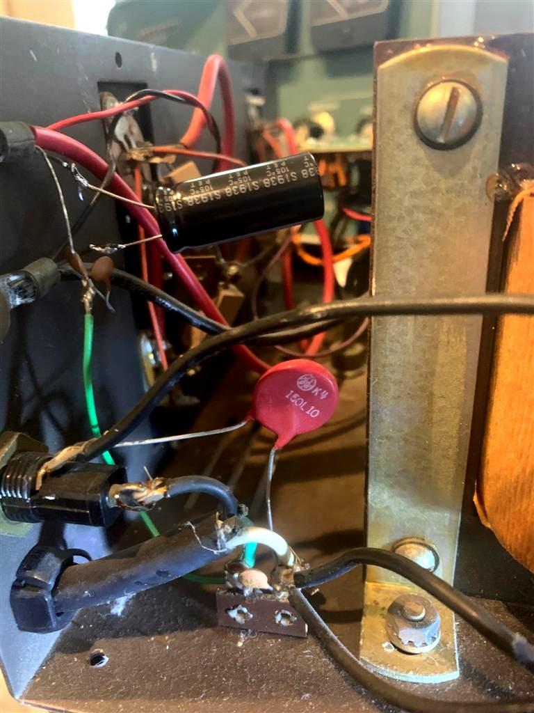
Most Astron supplies also have a dipped black or red metal-oxide varistor (MOV) across the transformer's primary winding, often labeled VR1 on the schematic. This is present to absorb incoming voltage transients. If it does its job, it could short out or have a very low resistance. On many supplies it is soldered directly to the primary winding wires of the transformer and not easily disconnected. If you've disconnected the secondary wires and the supply still blows fuses immediately, cut one lead of VR1 and measure it with an ohmmeter. If it shows anything under 1000 ohms, it's probably bad and should be replaced if you want to continue having some protection. The supply will still work without it however. When they do their job, they often become discolored or look burnt. If the supply still blows fuses without VR1 then the only part remaining is the power transformer, and if that's bad, you'd be better off buying another supply. Older supplies had the MOV near the AC Input and fuseholder, the reddish part in the photo below, provided by Tele KP4P (the red component labeled 150L10).
While rare, it's possible that a previous owner played with the power switch wiring and somehow ended up with a short circuit. One of the incoming power wires (black/hot lead) goes to the switch terminal #2. The other incoming power wire (white/neutral) goes to the switch terminal #3 and is used to illuminate the switch. The power transformer goes to the switch terminal #1, which makes contact with terminal #2 when the switch is turned on. The switch terminals are numbered on the side or rear of the switch.
Raw AC and DC Voltages:
These voltages were recorded on functioning power supplies with no load attached. The incoming line voltage was 118VAC. Your readings could vary by 10-20% depending on your line voltage and the accuracy of your equipment.
The RS35 is typical of a supply with a grounded transformer secondary center-tap lead. The SL15 is typical of a supply with a full-wave bridge rectifier and no center-tap lead.
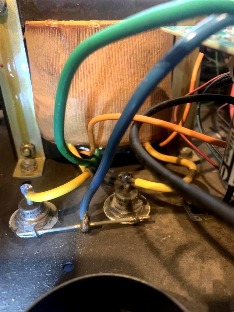
The High Current winding wires go to the main diodes or bridge rectifier(s) mounted on the chassis. The photo below, provided by Tele KP4P, shows these stud rectifiers in a real old supply.
The Low Current winding wires go to the regulator circuit board, points 5 and 6. ACV is measured across the transformer winding. DCV is measured at the filter capacitor or the output of the diodes. Ripple is the AC voltage measured at the filter capacitor or the output of the diodes. Excessive ripple voltage, especially with any load, is an indication that the relevant filter capacitor needs to be replaced.
| Supply and Winding | ACV | DCV | Ripple |
|---|---|---|---|
| RS35, High Current | 32.9 | 22.0 | 1 mV |
| RS35, Low Current | 40.4 | 27.0 | 8 mV |
| SL15, High Current | 18.0 | 23.1 | 2 mV |
| SL15, Low Current | 28.0 | 30.0 | 16 mV |
Testing the Raw DC Circuitry:
Use the ohmmeter and check the main diodes or bridge rectifier(s). With most meters, you would connect the positive or red lead to either terminal where the AC input (transformer) was connected to the diode or bridge, and connect the negative or black lead to the positive or common output terminal, the one that goes to the main filter capacitor. If the rectifier is connected with push-on terminals, disconnect all of them (write down where they went, of course). You should see about 10 ohms in this direction for each diode or terminal that the transformer was connected to. If a diode is shorted or open, it will be readily apparent. On the smaller supplies that use all four leads of the bridge rectifier, you must also test the negative half of the bridge. Connect the positive or red lead of the ohmmeter to the negative terminal of the bridge, and connect the negative or black lead to the terminal where the transformer was connected. You should see the same 10 ohm value on each terminal. Any indication of a shorted or open diode means you must replace the diode or bridge. If the supply uses two stud diodes, replace both of them. The threaded studs must be insulated from whatever they're mounted to. The hardware that's exposed under the power supply chassis or on the rear heat sink has 20 to 24 volts DC on it and must NOT touch ground. Some supplies have plastic caps over the exposed hardware. The rubber feet on the chassis elevate it enough in most cases. If there are two bridge rectifiers, replace both of them, since a failure of one could have over-stressed the other one. You could also replace a pair of bridge rectifiers with a single one that has a higher current capacity. The diagram below shows the four measurements you need to perform on a bridge rectifier. If your supply has stud diodes, just do the two right-hand measurements.
Check the main filter capacitor. (Some supplies have two large caps wired up in parallel. Astron used whatever they could purchase.) This cap can hold a charge for a long time, so you should discharge it through a low value (10 to 1000 ohm) resistor first. A shorted diode will have done this already but it pays to be safe. The voltage won't hurt you but it could damage your ohmmeter or some part on the regulator board if it contacts something it shouldn't. Connect the ohmmeter's positive or red lead to the positive terminal of the capacitor, and connect the negative or black lead to the negative terminal of the capacitor. You should see a low resistance at first, maybe 20 ohms, followed by an increasingly higher resistance, going up to several hundred ohms or more. If you don't see this action, or the resistance remains low, the main filter capacitor could be defective. Disconnect the cap if possible and measure it alone. Failure to see the resistance change as the capacitor charges means the cap is bad; replace it. Bulging and/or signs of leakage means the capacitor is bad; replace it. On the older supplies, the regulator board mounts to the capacitor with screws, so it's easy to disconnect. Newer supplies use caps with snap-in terminals that are soldered to the regulator board, making it a bit more difficult to disconnect it. Looseness of either terminal is also a bad thing; tighten the screws first if present, otherwise replace the cap. See this article for a list of the various main filter capacitor values.
If you have a Variac, reconnect the rectifier wires, plug the supply into the Variac and put a DC voltmeter across the main filter capacitor. Slowly increase the AC voltage; you should see a similar increase in raw DC voltage. If the DC voltage does not rise, you may have a shorted rectifier, a blown fuse, an open power switch, or a bad transformer. Some of these may cause the AC current to rapidly increase with just a few volts, which will blow the fuse if it gets too high. See the table above for the raw, unregulated DC voltages you should get on the high and low current supplies.
If the supply can only provide a very little bit of output current, then the voltage drops as if the supply went into foldback current limiting, it's very possible that the main filter capacitor is bad. I had this happen on a VS20M supply. It was set to 14.0V but when the load current got up to 5A, the output voltage started dropping down and eventually the supply gave up. It recovered when the load was removed. On this supply, the main filter cap was of the solder-in type and it was working - somewhat. After making sure the main rectifier diodes were OK, I pulled the capacitor; that revealed a nice black scorched area on the circuit board. I also had very high ripple (AC) voltage across this cap, on the order of several volts, with no load. That itself was a good enough indication of a bad cap.
Testing the Series-Pass Circuitry:
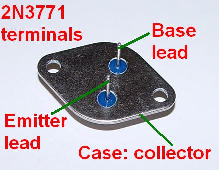
One to eight 2N3771 (or similar) transistors are mounted on the heat sink on the rear and/or sides of the power supply. On the newer models, they plug in to sockets, however the sockets are not anchored to the heat sink, so they will fall loose after you remove the screws holding the transistors in. On the older models, the wires were soldered directly to the transistor leads. You can make a quick check of all of them, and if problems are found, you could remove each one and test them separately (see below), however the best thing to do is replace all of them if any of them test bad. On the larger supplies, there's another 2N3771 driver transistor on the rear panel; remember to check this one as well. If any of the other 2N3771 transistors short, they can cause this driver transistor to go bad.
Use the ohmmeter. A transistor can be thought of as two diodes, so the resistance values should be about the same as what you got when measuring diodes: about 10 ohms for a good junction. For an NPN transistor, connect the positive or red test lead to the base terminal, and connect the negative or black lead to either the emitter or collector terminal; you need to test both paths. A zero reading indicates a short circuit. An infinite reading indicates an open circuit. Either condition means the transistor is bad. Reverse the polarity for a PNP transistor. The diagram below shows how you test these transistors:
Although it rarely happens, there can be leakage from emitter to collector, even when the other junctions test good. As a final test, measure the resistance from the emitter to the collector in both directions; you should get a lot more than 10,000 ohms. Note that this same test applies to all the other transistors used in the power supplies.
On the Astron power supplies, all of the collectors are connected to the incoming raw DC supply, which is the positive lead of the large filter capacitor. Each of the emitters is connected through it's own low-value (0.1 or 0.05 ohms) resistor to balance the current. The common junction point of these resistors is connected to the positive output terminal of the supply and also point (2) on the regulator board. That only leaves the bases; all of them are connected together through a thin wire that goes to point (4) on the regulator board. You don't need access to the heat sink or the back of the series-pass transistors; you can easily make this measurement from the top of the supply.
By the way, on those supplies with front panel ammeters, they actually measure and display the voltage across one of those low-value emitter-balancing resistors, and calibrate this as a current value. If the transistor driving that particular resistor is open, the ammeter won't indicate any current. If the emitter-balancing resistor is open, the ammeter will probably be destroyed when too much current flows through it. Check each of these resistors with an ohmmeter as well. Due to their low value, all you can do is see if they're open or not. The voltages on the series-pass transistor emitters (the leads going to those resistors) should be equal to the voltage at the output terminal when a small load is attached. As the load current increases, the voltage drop will increase slightly. You should see a slight voltage drop across all of the resistors with a moderate load, say 50% of the rated current, and this voltage drop should be present on ALL of the resistors. If one or more don't have any drop, chances are the series-pass transistor associated with that resistor is open.
If the power supply won't provide enough current to the load, it's possible that one or more of the series-pass transistor junctions or even the driver transistor (if present) is defective (open). You'd have to remove and test each one individually to see if this is the case. The photo below shows the terminal orientation. Note that the two pins are closer to one mounting hole than the other.
You should replace ALL of the series-pass transistors if ANY measure open or shorted, as the bad one(s) could cause too much current to pass through the remaining good ones, causing more damage. Always clean the old heat sink compound off the aluminum heat sink and the mica insulators under the transistors after you remove them. Every transistor and its mounting screws must be insulated from the chassis. Apply a thin but complete coating of fresh heat sink compound to both sides of the insulator before installing the new parts. Some of these compounds are hazardous to your health; read and heed the instructions found on the container.
There are silicone pads available to replace the mica insulators, and these need no heat sink compound. They make a much neater repair job. There are also insulating covers available that snap onto the exposed series-pass transistors (strongly recommended); see the parts list at the end of this article. Remember, these have 24VDC at basically unlimited current on their cases, so contact with a grounded wire would be a bad thing.
Testing the Regulator Board Circuitry:
There are several separate areas of concern on the regulator board; a short paragraph on each will follow.
The regulator board has a separate power supply. The power supply diodes could short out or open if a voltage spike comes in on the AC line. These could also take out the 470uF, 1000uF, or 2200uF 35V filter capacitor C1. Bulging or signs of leakage means the cap is bad; replace it. Also measure the AC and DC voltages across this cap; for the RS35, AC voltage should be under 10mV with no load, going up to perhaps 600mV at full load. DC voltage should be near 27V with no load, going down to perhaps 22V at full load. For the SL11, AC voltage should be under 30mV with no load, going up to perhaps 325mV at full load. DC voltage should be near 31V with no load, going down to around 25.5V at full load. A bad cap here will make for very poor output voltage regulation. If you have a meter that can measure capacitance, unsolder, remove, and measure each electrolytic capacitor and replace any that are more than 20% low in value.
CR6 is a transient voltage suppressor (TVS). If it has done its job to prevent damage due to an over-voltage condition, it will have some amount of low resistance (10 to 1000 ohms) all the time, and this will prevent the power supply voltage on the regulator IC from reaching its full value, about 29-31 volts. This lower-than-normal voltage can cause all sorts of odd problems; if the voltage creeps up or drifts, this part is probably bad. Unsolder one end and lift it out of the board; if the problems change, the part is bad. Replacement is the only way to deal with it. The supply will work fine without it, but it's there as cheap insurance, as they only cost about 25 cents.
The LM723 IC is hard to test other than comparing the voltages with the chart on the schematic. They're fairly inexpensive so replacement is the quickest way to deal with them. The "723" is a generic IC and it is made by several manufacturers with slightly different prefixes and suffixes. You want one in the 14-pin dual-inline package (DIP). These are fairly reliable but being socketed they're easy to replace.
The TIP29 driver transistor can be unsoldered and tested the same as the series-pass transistors. You might have troubles testing it while it's still in the circuit, due to interaction from the other components. Also test the components connected to this transistor. A shorted or leaky capacitor across the TIP29 transistor can cause the supply to output a higher than normal voltage that can't be adjusted.
The SCR in the over-voltage circuit could have shorted out due to a previous over-voltage condition. Measure across the power supply output terminals or the regulator points (2) and (3) with an ohmmeter; you should see several hundred ohms here; if it's less than 2 ohms, the SCR is probably bad. You can remove it for testing and if the supply runs normally, that was the problem. Also, the SCR could fire falsely when you turn the power supply on. Try shorting the gate lead to ground to see if it's a trigger problem, or remove it to see if the SCR itself is just bad. As with the TVS, the supply will run without it, but it's cheap insurance, as it will protect the load from an over-voltage condition, should something go wrong.
If Q1 is bad, it could trigger the SCR all the time or not at all. Test it with an ohmmeter like you would for the series-pass transistors, except reverse the polarity, since this is a PNP transistor. Connect the negative or black lead to the base, and the positive or red lead to the emitter or collector. The supply can run without it, but then you have no over-voltage protection.
There are two other diodes on the regulator board that can be checked with an ohmmeter.
The factory voltage adjustment pot on the board is an open construction, and can get dirty or even open due to the fact that it's used just once at the factory to set the output voltage. If the pot opens, it won't control the voltage and the supply may crowbar. Disconnecting the crowbar SCR will show that the output voltage is too high and the pot might not make any difference. Sometimes you can clean the pot but it is usually better to replace it, because it's likely to happen again. If the pot is dirty, adjusting it will cause the output voltage to jump around rather than change smoothly. Turn the supply off, run the pot from end to end several times, set it in the middle, turn the supply on, and adjust it properly. Note that the factory location for the regulator board mounts it upside down. If you DO have to replace the pot, use a sealed 10 turn pot and you might consider relocating it to the foil/solder side of the board so adjustment is a lot easier, as long as there's room when you reassemble the supply.
To test the over-voltage crowbar circuit (some supplies, such as the RS3 and RS4, don't have one, so you can't test it), you can either cause it to trip at the normal power supply voltage of 13.8 volts or elevate the output voltage to over 17 volts. With the power supply running with no load, connect a DC voltmeter to the output terminals and momentarily place a 1k resistor across R7, which is next to the voltage adjustment pot near the center of the regulator board. This will raise the output voltage considerably, which should cause Q1 to turn on and trigger the SCR, causing the supply to crowbar and reduce its output voltage to lower than 1V. Turn the supply off as soon as the voltage drops down, although the fold-back current limiting should prevent any damage. On supplies with meters, you should see under 1V and about 10% of the supply's rated current. On some supplies, the input fuse may blow. On one SL11, the AC input current was under 1A when the crowbar had been manually triggered in this way. Under normal fault conditions, such as a series-pass transistor shorting out, the AC input current could go much higher and should blow the AC line fuse.
Meters:
The analog meters used on Astron power supplies are 1mA DC movements. The voltmeter usually indicates 15V full scale, so there's a 15k resistor in series with the meter, in the form of a 20k potentiometer that's usually soldered to one of the terminals on the back of the meter. DC from the supply's output goes to the other terminal of the pot, and the other meter terminal goes to the negative output terminal or ground.
As said above the ammeter measures the voltage drop across one of the 0.1 or 0.05 ohm emitter balancing resistors that are in series with the emitter leads of each of the series-pass transistors. A resistor in series with the meter, in the form of a 1k potentiometer that's usually soldered to one of the terminals on the back of the meter, turns this into a 1V full scale indicator. The scale is determined by the output capability of the supply and by how many series-pass transistors divide up the output current. For example, on an RS35M supply, the meter can indicate up to 40A and there are four series-pass transistors, so each one provides 10A. The voltage drop across the 0.05 ohm resistor is therefore 0.5V, and the meter calibration pot is set to roughly 500 ohms.
Each meter can be tested using a battery and a series resistor, calculated to give you something between 0.5 and 1.0mA. For example, a 1.5V battery and a resistor having a value of 1.5k, 1.8k, or 2.2k will give you 1mA, 0.83mA, or 0.68mA respectively. Similarly you can use a 9V battery and a 10k resistor to give you 0.9mA. Any of these are sufficient to prove whether the meter movement is good or bad. Looking at the meter from the rear, the negative terminal is on the right; they are marked but you need a strong light to see the legend.
The most common failure occurs when the series-pass transistor, feeding the emitter-balancing resistor that the ammeter is across, shorts out and the emitter-balancing resistor opens, thus putting a whole lot more current through the ammeter, and the meter burns out. Another common failure is when the same series-pass transistor goes open, providing no current to the load and no voltage drop across the emitter-balancing resistor, so the meter reads nothing. At least you can verify whether the meter itself is still good, especially if you know the supply is putting out the right voltage and can power a decent load.
Miscellaneous Items:
There is usually a disc capacitor and an electrolytic capacitor installed right at the output terminals to suppress any oscillation or instability. These should be visually checked for burnt or bulging condition and replaced if necessary.
Visually check the entire supply for any burnt, leaky, or bulging components and replace them.
Some supplies have a wire that connects the negative output terminal to a nearby ground screw on the chassis, while others don't. Some people believe that this wire should be present while others believe it should be removed. I've never had a problem with ground loops because of this ground wire, but there could be situations where it can get you into trouble. Don't rely on chassis ground to conduct the negative power to the load. You can disconnect and tape it up if it bothers you.
Some supplies will go into fold-back current limiting when a high-capacitance load is attached, due to the high inrush current. Dana KD2HYH had such a problem with his VS-35M and a Yaesu FTDX-3000D radio. Astron recommends increasing the value of R4 from 300 ohms to 500 ohms to resolve this issue. In Dana's case, R4 actually measured 270 ohms. Increasing it to 470 ohms took care of things. This may also explain why some supplies do the same thing when halogen bulbs are used as loads.
Final Testing:
Set the voltage adjustment pot on the regulator board to about mid-range. If your unit has front panel voltage and current adjust pots, set them fully clockwise. Make sure all the wires are connected. Attach a DC voltmeter to the output terminals. If you have a Variac, plug the supply into that, turn the power switch on, and slowly raise the input AC voltage. You should see the DC output voltage increase and level off around 13 volts by the time you get up to 70 to 80 volts AC. If the output voltage continues to increase as you increase the input AC voltage, something is wrong, possibly a shorted series-pass transistor, a shorted TIP29 transistor, or a defective 723 regulator IC. If the voltage gets too high, the over-voltage crowbar circuit will activate and short the power supply output.
If the voltage levels off at around 13 volts, continue to raise the input AC voltage to 120 volts. The DC output voltage should remain where it leveled off. Reach under the regulator board and set the voltage adjust pot to get 13.8 to 14.0 volts at the output terminals, 15V if you have an adjustable voltage pot on the front set to maximum.
If you don't have a Variac, all you can do is turn the supply on and watch the results. A properly working power supply will come immediately up to the set voltage and stay there.
Apply a load such that you draw a few amps from the supply. An incandescent automotive light bulb or headlamp will work great for this; a halogen bulb has a very low resistance when cold and the supply will likely shut down due to excess current. This shutdown is a design feature and is known as fold-back current limiting. The current will drop to a few amps and the output voltage will be in the 1 to 3 volt range. If the supply does this, you've exceeded its current rating. This will likely happen when light bulbs are used as loads. There are a couple of load project articles on the Astron page that might give you a few ideas. DO NOT USE ANY VALUABLE ELECTRONIC EQUIPMENT AS A LOAD. The DC output voltage at the power supply terminals should not change more than a few millivolts, but you'll need a digital voltmeter to see this. The voltage measured at the load will likely be lower depending on how much current is passing through the wires and connectors.
Do not confuse this fold-back current limiting shutdown with the action of the SCR crowbar circuit. When the crowbar fires due to excess output voltage, it shorts the output terminals, reducing the voltage to about 0.5 to 1.0 volts. The only way to reset the crowbar circuit is to shut off the supply and let everything discharge such that the output voltage is lower than 0.5 volts, and this could take 15-30 seconds.
If you have a good digital voltmeter, connect it to the output terminals and measure the AC voltage coming out. You should see very little, less than 1 millivolt. If you see a whole lot more, the main filter capacitor is probably bad and it should be replaced. This will be more evident with a load attached.
If you have the ability to load the supply to its full CCS rating, do so. The DC output voltage should not change and you should still see less than 1 millivolt AC. If you can load the supply to its full ICAS rating, try that too.
Remember that a variable supply (VS) is only capable of full rated power at 13.8VDC. You must derate it at lower output voltages. For example a VS50 is good for 37A continuous at 13.8VDC but only 22A continuous at 10VDC and only 10A continuous at 5VDC output. Other supplies have similar numbers. So don't expect to get 37A out of the supply at its minimum output voltage. The supply may go into current limiting or fold-back.
If your power supply has metering and you have an accurate digital voltmeter, now might be a good time to calibrate them via the pots on the back of each one or near the meter switch. (Some of the older supplies had fixed-value resistors but you could replace those with pots if you want.) First, turn the supply off and let everything discharge for a few minutes. Adjust the front panel meter zero screws so the pointers rest at zero. Turn the supply on and adjust the voltmeter first, then using a known value resistive load, calculate the current, and adjust the ammeter. You want a load current to give you at least 50% of the full-scale meter indication. Remember that the ammeter is only displaying the current through one of the series-pass transistors so it might give a different indication than a true series ammeter.
If your power supply has front panel voltage and current adjustments, verify that these are working properly.
Most Astron power switches are illuminated with an internal neon bulb. This bulb has a limited lifetime, which could be 10 to 15 years if you're lucky. The bulb will start to flicker and then cease to light up even though the power supply is functioning normally. Replacement of the switch is the only way to restore operation. Just be careful to match the terminal numbers. Or add a +12v LED indicator to the front panel and wire it across the output of the supply.
Make sure there are four rubber feet under the supply, especially if it's an older one that used stud diodes mounted through the chassis bottom. The studs carry raw DC voltage and must NOT touch ground. 1/4 inch tall feet are recommended, 3/8 to 7/8 inch square but other shapes and sizes will also work.
LM723 Regulator DC Voltages:
The table below documents the voltages shown on their respective schematics as well as what I found on normally functioning power supplies. The input voltage at the time of testing was 118VAC. There was no load attached. The negative terminal of the power supply was used as the reference for all voltages. All readings were taken with a Fluke 189 digital multi-meter.
| Pin | SL11A | Meas | RS35M | Meas | Notes |
|---|---|---|---|---|---|
| 1 | - - - | 0.0 | - - - | 0.0 | |
| 2 | 13.1 | 13.1 | 13.1 | 13.4 | |
| 3 | 13.8 | 13.8 | 13.1 | 13.8 | Equals Vout |
| 4 | 7.2 | 7.2 | 7.2 | 7.0 | Pins 4, 5, and 6 should |
| 5 | 7.2 | 7.2 | 7.2 | 7.0 | all be equal in voltage. |
| 6 | 7.2 | 7.2 | 7.2 | 7.0 | Varies on VS supplies |
| 7 | 0.0 | 0.0 | 0.0 | 0.0 | |
| 8 | - - - | 0.0 | - - - | 0.0 | |
| 9 | - - - | 8.8 | - - - | 8.7 | 6.2V lower than pin 10 |
| 10 | 14.8 | 14.9 | 14.8 | 14.9 | 1.1V higher than Vout |
| 11 | 29.0 | 30.7 | 29.0 | 27.1 | Almost 723 voltage |
| 12 | 29.0 | 30.7 | 29.0 | 27.2 | Almost 723 voltage |
| 13 | 18.1 | 16.3 | 16.1 | 16.3 | |
| 14 | - - - | 0.0 | - - - | 0.0 | |
| Raw | 23.0 | 23.2 | 28.0 | 22.3 | Unregulated voltage |
| 723 | 29.0 | 30.8 | 29.0 | 27.4 | Unregulated voltage |
| Vout | 13.8 | 13.8 | 13.8 | 13.8 | Regulated output |
The "Raw" voltage is the unregulated voltage across the main (large) filter capacitor. The "723" voltage is the voltage being supplied by the two diodes on the regulator circuit board that feed the large filter capacitor on that board. This provides voltage to the LM723 regulator IC. "Output" is the output voltage at the power supplies output terminals.
Working Supply Voltages:
The following voltages were recorded on a 2002-vintage RS35M in good working condition with the output voltage set to 14.00 volts. "Raw" is the unregulated voltage across the main (large) filter capacitor. "EBR" is across one of the 0.05 ohm series-pass transistor Emitter Balancing Resistors. "Vout" is the output voltage at the power supply output terminals. I also measured the voltages on the TIP29 driver transistor as well as point 4 on the regulator card that feeds the bases of the series-pass transistors.
| Meas / Load> | None | 20A | 40A |
|---|---|---|---|
| Raw VDC | 22.4 | 18.8 | 17.0 |
| Raw VAC | 0.02 | 0.24 | 0.48 |
| EBR VDC | 0.00 | 0.24 | 0.48 |
| Output VDC | 14.00 | 13.98 | 13.96 |
| TIP29 Emitter | 14.51 | 15.88 | 16.42 |
| TIP29 Collector | 27.30 | 24.04 | 21.86 |
| TIP29 Base | 15.09 | 16.57 | 17.19 |
| Point 4 | 14.50 | 15.09 | 15.59 |
At 40 amps, the output voltage was 13.995 volts and the voltages on one series-pass transistor were: E: 14.48V, B: 15.57V, C: 16.70V.
On this supply, foldback current limiting occurred at 41 amps. At that point the output voltage dropped to 0.75V and the load current was 4A.
SL11 voltages are similar. "Output" was measured at the DC output, a standard Motorola two-pin mobile radio power connector. This is fed by two undersized wires, which exhibited excessive loss, evident by the poor output regulation at this point. This condition affected ALL voltage readings. I'm sure the supply internally was doing much better. The junction of the two emitter-balancing resistors was not accessible due to the compact size of the supply and placement of the regulator board. This supply was capable of almost 20 amps of current before the current limiting kicked in.
| Meas / Load> | None | 6A | 12A |
|---|---|---|---|
| Raw VDC | 23.8 | 20.3 | 18.6 |
| Raw VAC | 0.02 | 0.33 | 0.60 |
| Output VDC | 13.8 | 13.6 | 13.5 |
I measured the voltages on the LM723 regulator on the same RS35 supply with no load and with a 35A load, and on the series-pass transistor nearest the main filter capacitor, as it was the easiest to access. All four transistors had very similar readings. The output voltage was set to 14.00 volts. The negative output terminal was used for ground. The results are tabulated below.
| Pin | 0A | 35A |
|---|---|---|
| 1 | 0.00 | 0.00 |
| 2 | 13.38 | 14.43 |
| 3 | 14.00 | 13.98 |
| 4 | 7.01 | 6.99 |
| 5 | 7.01 | 6.99 |
| 6 | 7.01 | 6.99 |
| 7 | 0.00 | -0.02 |
| 8 | 0.00 | 0.00 |
| 9 | 8.84 | 10.71 |
| 10 | 15.06 | 17.07 |
| 11 | 27.23 | 19.80 |
| 12 | 27.41 | 22.30 |
| 13 | 16.38 | 18.39 |
| 14 | 0.00 | 0.00 |
| E | 14.00 | 14.40 |
| B | 14.49 | 15.41 |
| C | 22.31 | 17.21 |
Other Problems:
One reader reported a big arc and blown fuses when he connected his RS35 to another piece of grounded equipment. Turns out his power supply did NOT ground the negative output terminal, and it also had individual stud rectifiers. One of the insulators on the rectifiers failed, so it applied +24 Volts to the grounded chassis of the power supply, offsetting the output terminals accordingly. When the supply was connected to a piece of grounded equipment, that 24 Volt potential was shorted out, blowing the main power supply fuse as well as a fuse in the grounded equipment. It was just an odd set of circumstances.
Most Astron power supplies connect the negative output terminal to the chassis, which is grounded through the power cord. If you have any supplies with exposed stud rectifiers, you should be careful NOT to ground those studs. The RS35 mounts them to the bottom of the chassis; larger supplies mount them on a small heat sink on the rear of the chassis. Verify that the studs are fully insulated from the chassis.
Commonly Replaced Parts:
The parts listed below are common replacement parts. I keep a few of each on hand. All prices and suppliers, unless otherwise noted, are from Mouser in 2012. For small parts orders (under about $6), I usually go with Digikey and first-class USPS shipping.
Carling Curvette rocker switch: LRA211RSB/125N, about $2.00.
25A 200V diode bridge: about $2.50 (All Electronics).
50A 1000V diode bridge: about $7.50 for 10 from China (ebay).
60-70A 100-200V stud rectifier: about $8 each.
1N4007 general-purpose 1A 1000V diodes: about $0.07.
P6KE39A 39V transient voltage suppressor: about $0.25.
TIP29 transistor: about $0.30 (All Electronics).
2N3771 series-pass transistor: about $2.50.
Assorted slow-blow fuses: about $0.20 to $1.00 each.
Rubber stick-on feet: $0.10 to $0.50 each.
Aavid Thermalloy 8909NB TO-3 snap-on transistor covers: $9.90 for 20 (ebay).
Keystone 4601 TO-3 transistor sockets: $2.76 each.
1000uF or 2200uF 35V capacitor on regulator board: about $0.75.
Main filter capacitor (SL, snap-in, Panasonic brand): between $5.00 and $8.00.
See this article for a list of the various main filter capacitor values.
See this article for a list of the various crowbar SCRs and some possible replacements.
Contact Information:
The author can be contacted at: his-callsign [ at ] comcast [ dot ] net.
Back to the top of the page
Up one level (Astron index)
Back to Home
This page originally composed on 15-Jan-2013
Diagrams, photos, text, layout, and hand-coded HTML © Copyright 2013 and date of last update by Robert W. Meister.
This web page, this web site, the information presented in and on its pages and in these modifications and conversions is © Copyrighted 1995 and (date of last update) by Kevin Custer W3KKC and multiple originating authors. All Rights Reserved, including that of paper and web publication elsewhere.