RadioShack™, Archer™, Micronta™ and and Realistic™ Equipment
Compiled, HTML'd and Maintained by Mike Morris WA6ILQ
Formerly Maintained by Robert Meister WA1MIK (SK)
I know very little about this equipment!
| Back to Home |
Technical Information on RadioShack™, Archer™, Micronta™ and and Realistic™ Equipment Compiled, HTML'd and Maintained by Mike Morris WA6ILQ Formerly Maintained by Robert Meister WA1MIK (SK) I know very little about this equipment! |
Quick Links:
Two-way / Ham Radios
Scanner Receivers
Test Equipment
Accessories and Other
Weather Radios
Weather Radio Interfacing Articles
Weather Radio Test Files
We have no information on the RS-labeled MURS (VHF) and GMRS or FRS (UHF) radios.
|
Radio Shack began operations with Unicomer Group in Central America in 1998 as a North American style
store selling technology products and accessories. In May 2000, the company dropped the Tandy name altogether, becoming RadioShack Corporation. The last RadioShack printed catalogs that were mailed out to the customer mailing list were in 2003. On February 5, 2015 RadioShack filed for Chapter 11 bankruptcy protection. They were later acquired by Sprint. Several hundred corporate-owned stores remained open but most of franchised stores closed over the next nine months. RadioShack was delisted by New York Stock Exchange in early 2015. In May 2015, General Wireless Inc. bought the company's assets, including the RadioShack brand name, products, trademarks, web page, and related intellectual property, for US$26.2 million. In 2015 Unicomer Group acquired RadioShack International Brand, Intellectual Property and Franchise rights for Central America, South America, and the Caribbean. In 2023 Unicomer Group acquired RadioShacks intellectual property assets and domains in about 70 countries around the world including the United States. |
| www.radioshack.com appears to tbe the only thing left of the old Radio Shack. |
| Some additional history courtesy of a reader. |
If anyone has any information that should be here (including scans or PDFs of manuals) please drop an email to the page maintainer.
You should read this Radio Shack Introductory Information article before any of the other articles here in this section.
Some of the support-related information presented here may be out-of-date.
Usually any available service manuals can be ordered by calling RadioShack.com at 800-241-8742. Some manuals are no longer available. If you have a local store they may have intelligent folks that can look up manual numbers by radio name (i.e. HTX-10 = 19-1110), others have vertical ambulatory hominid life forms of zombie intelligence that are only capable of selling cellphones or responding to any questions with stupid looks ("You've got questions, we've got cellphones™"). Support is
rapidly failing for this company.
If you are trying to find info on older equipment (a lot of it didn't have a model number sticker on it) then this very well done web site (not affiliated with RS) that has scans of catalogs from 1939 to 2005 may be of interest... http://www.radioshackcatalogs.com
Here's what we have so far... if you want to donate anything feel free to contact the page maintainer listed above.
We're not really interested in any entertainment electronics devices unless they would be useful to a ham or a repeater builder.
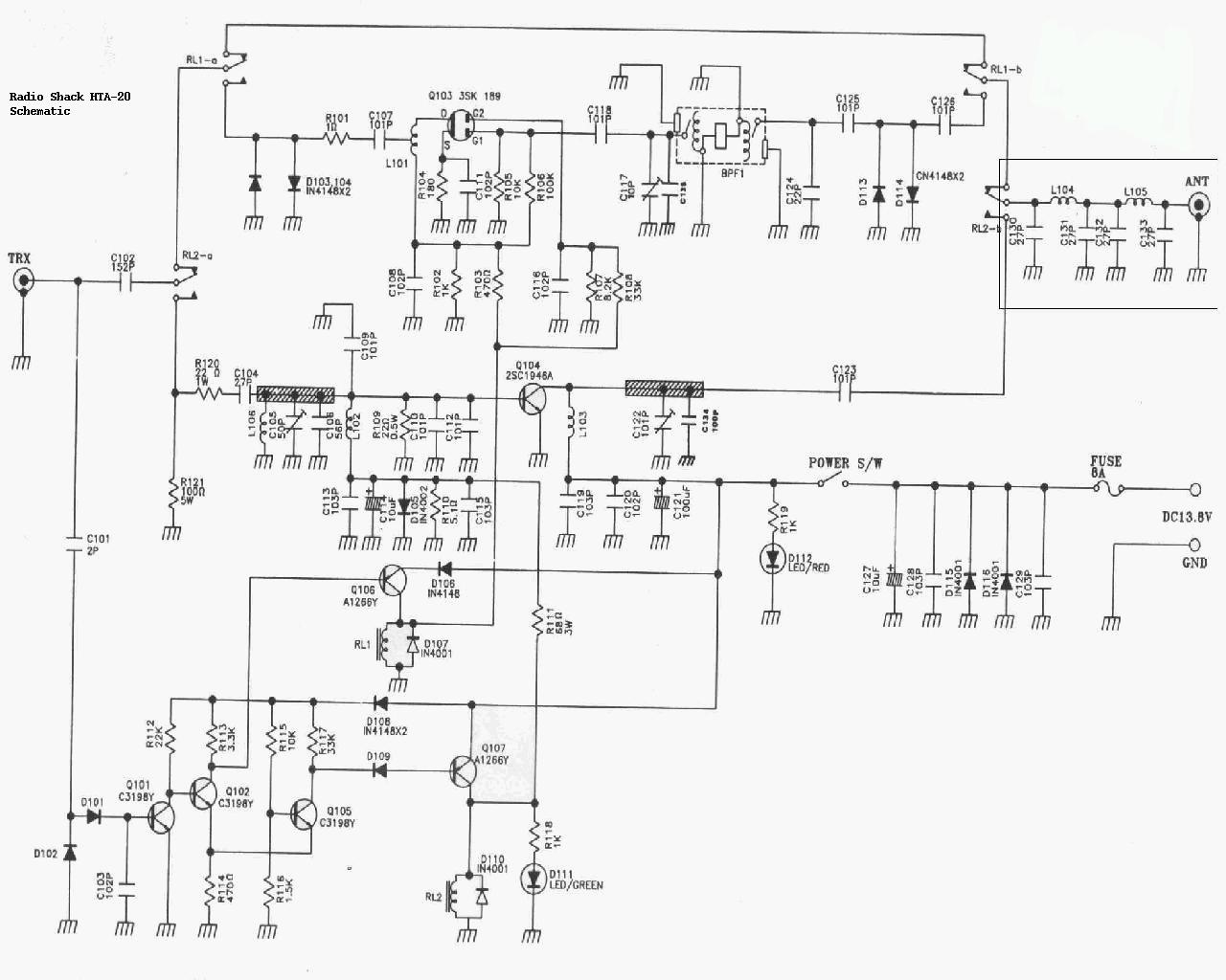
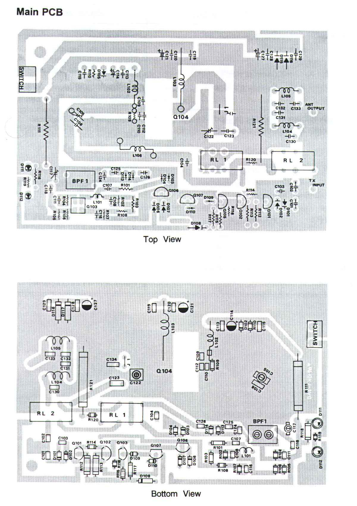
| HTA-20 VHF Mobile Power Amplifier | |
|
|
Anybody have the service manual? Until one turns up, here's the schematic, and here's the board layout. |
|
|
Owner's Manual
2.1 MB PDF donated by KB9QBT This is a 144-148 MHz 30w FM out, 1/2 to 5w in FM only amplifier |
|
|
Exploded Parts View 20.2 kB PDF |
|
|
Care and Maintenance |
|
|
Features |
|
|
Frequently Asked Questions |
|
|
Operation |
|
|
Parts List |
|
|
Preparation |
|
|
Specifications |
|
|
Troubleshooting |
| HTX-10 Ten Meter Mobile Transceiver | |
|
|
Owner's Manual 1.05
MB PDF donated by Skipp This is a 28.0-29.7 MHz 25w SSB and FM, 7w AM unit |
|
|
Service Manual 3 MB PDF A note from the donor: Attached are the HTX-10 schematics and manuals. The HTX-10 PDF manual with schematics from the RadioShack service manual is pretty poor. BUT ! The Albrecht AE485s and AE485s_25W schematics are VERY similar to the HTX-10 schematic and can be used (along with what's in the HTX-10 book) to more easily figure out what you need to do to work on your HTX-10. Real HTX-10 Schematic only 405 kB PDF donated by Paul N2XZF AE485s schematic AE485s_25W schematics |
| HTX-100 Ten Meter Mobile Transceiver | |
|
|
HTX-100 Microphone Amplifier analysis and improvement 319kb MS Word DOC file by Jim Poll WB5WPA |
|
|
Service Manual 5.6 MB PDF |
|
|
Owner's Manual 1.16 MB PDF |
|
|
Parts List 21kb MS Word DOC file |
|
|
Care and maintenance |
|
|
Frequently Asked Questions |
|
|
Features |
|
|
Installation |
|
|
Operation Guide |
|
|
Specifications |
|
|
Troubleshooting |
| HTX-200 Two Meter Handheld Transceiver | |
|
|
Owner's Manual 1.06 MB PDF |
|
|
Photo |
|
|
Parts List |
|
|
Care and Maintenance |
|
|
Frequently Asked Questions |
|
|
Features |
|
|
Operation Guide |
|
|
Preparations |
|
|
Special Features |
|
|
Specifications |
|
|
Troubleshooting |
|
|
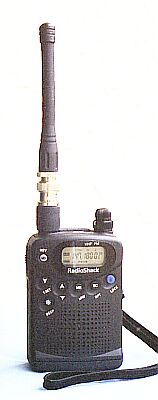
This is a mini-transceiver that was made by Standard Radio for RS. It delivers 200mW
output with 2 "AA" batteries (3 volts) or a full 2 watts (2 meters) with external 9
Volts DC. You can store a calling channel and up to 30 frequencies in memory for quick
access. The radio has built-in 47-tone CTCSS encode and decode, programmable repeater
offsets plus an LCD display with LED backlight, 10-step signal strength meter and
low-battery indication. An SMA-type jack lets you connect an external antenna. Size: 3"3/8 x 2"5/16 x 1"1/16 ", less antenna. Requires 2 "AA" batteries or a DC adapter #273-1815, or any external source of clean 9 vDC. I used a belt pouch with 6 "D" cells in it and it lasted a month. The stock antenna is junk, use a Smiley slim duck. It does not program like any other radios I've used, it could be called cumbersome. The menu system is not at all intuitive. The display is small and hard to read, the speaker audio is weak. If you are in MARS or CAP you can open up the transmit side from 142.000 to 149.885 by pressing and holding the "SC" button while turning the radio on. Some folks report having to do it twice or even three times to "take". The display will report the new transmit range when you are sucessful. To undo the mod just repeat the sequence again. Note: If you build up your own speaker-mic or an external equipment interface you need to realize that the HTX-200 and 400 use a push/pull audio stage that must be connected to a totally floating speaker. The speaker audio amp will self destruct if you connect either side of the External Speaker connector to ground. You want to have NO connection between the speaker side and the microphone side of the speaker-mic wiring. If you are interfacing some other device, perhaps an APRS TNC, you will have to include an audio transformer on the speaker connection. The microphone side uses an normal ground connection - the sleeve of the microphone plug. The HTX-200 2m radio is part number 19-1102, the HTX-400 UHF radio (listed below) is 19-1104. |
| Other Info Common to the HTX-202 and HTX-404 The 202 is the 2 meter HT and the 404 is the 440 MHz HT that were made by Standard for Radio Shack and loosely based on the Icom IC-02 and 04 design. From a ham via email: I worked in a RadioShack store in Oregon in 1996. During this time I sold several HTX-202s to local hams. On several ocasions Hams would come in asking me to confirm if they were made by Icom. Apperently it is still widely believed the 202 and 404 were made by Icom because they accept the Icom batteries. I asked TWO district managers about this, and looked for myself inside Tandy's records. I can tell you DEFINITIVELY that those RadioShack units were made by STANDARD. I, along with other sales associates, was told NOT to reveal this to the public. To this day I have no idea why. I also spoke to a Standard Rep one year at a ham swapmeet, and HE told me OFF THE RECORD that the RadioShack 202 and 404 were, in FACT made for RadioShack by Standard. I lost my job when it got back to my District Manager that I had inquired directly of Standard about this. I hope this will help put the question to rest. Another person submitted this historical account of these two radios: The HTX-202 and HTX-404 were manufactured by Maxon in South Korea, not by Standard Radio. I was the buyer (product manager) for specialized radio equipment, and personally spec'd the HTX-202 and HTX-404 (as well as the Uniden ten-meter transceiver and the first Maxon GMRS transceiver) brought into the line. As you can imagine, several of us on the merchandising staff were hams. We were in a unique position to "pay back" our great hobby by making reasonably-priced and decent gear available to the new no-code Techs. From December 1979 through July 1992, I was responsible for RadioShack's "27-series" (component parts and accessories) and the "22-series" (test equipment, power supplies, radar detectors, and specialized radio equipment (CB and scanners were handled by another great buyer and ham). One caution: the length of the two screws that hold the belt clip to an back of the HTX-202 or 404 is critical. If they are too long, the screws will contact the circuit board inside the radio and short things out. Make sure your screws are the appropriate length or you will have some serious problems. Since RadioShack as abandoned their amateur radio customers does anyone know of anyone that services any of the RadioShack branded amateur radios? Please contact the page maintainer above and we'll be happy to put a pointer here. |
|
|
|
Maxon took the HTX-404 design and made their "GMRS 210" series radios from it. The accessories made for the Maxon fit the 202 and 404 just fine. |
|
|
Expanding the coverage in the HTX-404
From the owners manual: Out of the box this radio covers only 440-450 MHz. A few keystrokes opens it up to 430-450 MHz. As easy as it is to do, why not? The extra coverage can be useful sometimes, for example in 2m transmitter hunts (146.565 is the hidden transmitter frequency in many areas, and 439.695 is the third harmonic. By listening there I can walk up to within a few feet of the fox. And all it costs is a few keystrokes.) |
|
|
A"cheat sheet" for the HTX-202 Also applicable to the HTX-404 if you mentally replace the 144s and 148s with 440 (or 430 if you've read the article immediately above) and 450. |
|
|
Replacing the Memory Backup Coin Cell in the HTX-202 and HTX-404 Handheld Radios By by Richard Luts KD4SEV and Craig LaBarge WB3GCK. |
|
|
An Overview of the DTMF - PL Design
defect in the HTX-202 and HTX-404 By Barry Sloan VE6SBS This well written article explains why the HTX202 and HTX404 have DTMF control problems... why you can't run both subaudible tone encode and DTMF at the same time. This is a local (at www.repeater-builder.com) copy of the web page at the VE6SBS web site only because that site was down several times after I referred folks to it. I decided to put a local copy here at repeater-builder just in case Barry's web site went away completely. |
|
|
When you power up your HTX the internal microprocessor runs a self-check routine that among other things does a sanity check on the radios configuration (i.e. frequency step info, etc), the frequencies held in the memorized channels, the CTCSS tone information and a lot more. All of this is held in a section of RAM that is powered by a coin cell. The self-check routine looks for scrambled data, and if found, stops everything and displays the dreaded "ER 1" code. The RadioShack manuals only mention of "ER 1" says that the coin cell getting old can cause an "ER 1" error. Personally, I think there is a bug in the programming (in the firmware) because I've had three of these radios and all seem to get scrambled RAM now and then, even after I've replaced the coin cell. To clear the "ER 1" error you have to give the radio its own version of the three-finger salute: turn the radio on while holding down the button above the PTT bar and the "D" button on the keyboard. This totally wipes the memory, then you get to reload all the memory channels. |
|
|
One nice thing about the HTX-202 and 404 is that on squelched receive they draw only about 20 milliamps and a single set of AA penlight cells will last a week of receiving. Most newer HTs draw 150 ma (or more) and with the smaller and smaller size HTs the batteries get smaller also. I have an HTX202 and an HTX404 that I bought primarily for tossing in my "go bag" (i.e. to use in emergency communications support). I have the penlight packs for the radios as well as ni-cads, plus spare antennas in the kit. I really like the fact that the antenna connector is a common BNC as that makes the antenna situation very flexible - a rubber duck for close in work, a 50-foot BNC extension cord when needed, a mag mount on a large steel pizza pan or metal trash can lid tossed on the roof for outlying areas, or even a small beam antenna if needed. Another nice feature is that it has a better receiver with a real front end... it does not cover DC to daylight which makes it a lot less prone to grunge and intermod than most newer HTs. |
|
|
Battery packs for the 202 and 404 are still available from the Batteries America Radio Shack page. Their choices include their own 1.8ah and 2.7ah packs, clones of the BP5, BP7 and BP8 and a holder for eight AA penlight cells that is perfect for EmComm situations. |
|
|
The original "wall wart" charger part number is 19-1120. The label on the stock charger says "DC12V 100mA" and the connector is center pin positive. While you can use a 13 volt or 14 volt unit at a higher current rating you really want to keep the actual DC current through the cells to under 1/10 the milliamp-hour (MAH) rating of the cells to maximize the life of your NiCad or NiMH battery pack - i.e. if you are using 1800mah cells you want to keep the current to 180ma or less. Yes, it will take 10 hours to recharge the battery, but you won't cook the cells. Personally, if I have the time I switch in some additional resistance and cut the charge rate to 1/2 normal and let it take 20 hours. My battery packs last a lot longer. |
|
|
Always us the LOW power setting on an unknown, unchecked antenna, before you use HIGH power. If there is a high VSWR protection circuit in the HTX-202, it doesn't work well! At least it didn't in mine! I had to replace the final output transistor in mine because of a bad antenna. And these transistors are getting very hard to find. |
| HTX-202 Two Meter Handheld Transceiver | |
|
|
KB8ZCJs fix for an intermittent transmitter |
|
|
Owner's Manual 1.5 MB PDF |
|
|
Service Manual 9.1 MB ZIP NOTE: This zip file contains 70 seperate files, one file per page side, and two files per half-schematic, plus the schematics themselves are a little blurry. If anybody has a paper copy we can borrow we'd appreciate the chance to get it scanned into a nice sharp PDF file with wide-page images for the pull-out schematic pages. Look at the GE LBI "full page" scans to see just what we can do... Here's the above 70 files as one 11 MB PDF... Here's the above 70 files as one 3 MB PDF - the same file just shrunk... the bigger file is a little bit more readable... |
|
|
Care and Maintenance |
|
|
Detailed Parts List |
|
|
Exploded Parts Drawing |
|
|
Errors and how to fix them
Describes the ER1 and ER2 situations. ER1 is a checksum error in the radios RAM
memory, and ER2 is a VCO out-of-lock error... and when it shows up they say "have
the transceiver repaired by a authorized service center". Thats a big help... For what it's worth the ER1 is an easy fix, see the article above about replacing the coin cell. |
|
|
Frequently Asked Questions |
|
|
Features |
|
|
Hints and Tips |
|
|
Operation This file has the basic information you need to use the radio. |
|
|
Preparation |
|
|
Specs |
|
|
Specs and Notes 32 pages of info in a 129 kB PDF |
|
|
Troubleshooting |
| HTX-204 Dual Band Handheld Radio | |
|
|
We have no manuals for the 204 dual band handheld yet, but battery packs for the 204 are still available from the Batteries America RadioShack page. |
|
|
Care and Maintenance |
|
|
Parts List |
|
|
Features |
|
|
Operations I |
|
|
Operations II |
|
|
Operations III |
|
|
Preparation |
|
|
Specifications |
| HTX-212 Two Meter Mobile Transceiver | |
|
|
Owner's Manual 247 kB PDF |
|
|
Service Manual 3.1 MB PDF |
|
|
Parts list |
| HTX-242 Two Meter Mobile Transceiver | |
|
|
Owner's Manual 119 kB PDF |
|
|
Special Features |
|
|
Service Manual 3.3 MB PDF |
|
|
Parts List |
|
|
Exact replacement display illumination bulbs are available. The bulbs are 6.3 volt
at 40 ma with wire terminals. As of Nov 2011 Mouser has them in in stock - they are
made by both Chicago Miniature and by JKL Components as part number 1730
and are rated at 10,000 hours. The JKL data sheet is
here and Mouser's web page is
here
if they haven't moved it. The JLK part is 38 cents each, or $3.36 for ten.
Chicago Miniature also makes them under the same part number at 60 cents each,
or $5.30 for ten. Or you can replace the bulbs with white LEDs - but if you do you
that you may have to change the series resistors. There are seven sets of two 100
ohm surface mount resistors in parallel that are involved. Thanks to Larry Anderton WA7YLI
for the info. In January 2012, Larry sent us an update: Previously I had identified Mouser part number 560-1730 as a correct replacement for the display backlight lamps in the radio. I just received those lamps and discovered they are NOT correct, in that they are 5 mm in diameter rather than the correct 3 mm. After investigating, I found that the Mouser online catalog is incorrect. It stated that part number as being a T1 size lamp, when in fact it is a T1-3/4 size lamp. As a result, the information I provided earlier is incorrect. |
| HTX-245 Dual Band Handheld Transceiver | |
|
|
MARS and CAP Addendum 239 kB PDF |
|
|
Care and Maintenance |
|
|
Operations |
|
|
Service Manual 4.4 MB PDF |
|
|
Exploded View 185 kB PDF |
|
|
Frequently Asked Questions |
|
|
Features |
|
|
Parts List |
|
|
Preparation |
|
|
Special Features |
|
|
Specifications |
|
|
Parts List: HTX-245A |
| HTX-252 UHF Mobile Transceiver | |
|
|
Owner's Manual 253 kB PDF |
|
|
DTMF Mobile Microphone Schematic 21.6 kB PDF |
|
|
Service Manual 3.7 MB PDF This manual is for the Albrecht AE-540 which is very close to the HTX-252. Interestingly enough, the photos are of a unit with the "RadioShack" name on it. |
|
|
Parts List |
| HTX-400 UHF Handheld Transceiver | |
|
|
Owner's Manual 1.2 MB PDF Most of the comments on the HTX-200 (above) apply to this radio as well. |
|
|
Exploded View 38 kB PDF |
|
|
Parts List |
| HTX-404 UHF Handheld Transceiver | |
|
|
Check the notes above on the HTX-202 as most of them apply to the 404... it's the same radio except for the frequencies... |
|
|
Manual Conventions |
|
|
Owner's Manual 1.47 MB PDF |
|
|
RF Schematic 92 kB PDF |
|
|
Digital Schematic 80 kB PDF |
|
|
Advanced Operation |
|
|
Care and Maintenance |
|
|
Detailed Parts List |
|
|
Errors and how to fix them |
|
|
Frequently Asked Questions |
|
|
Features |
|
|
Memory |
|
|
Operation This file has the basic information you need to use the radio |
|
|
Power sources |
|
|
Preparation |
|
|
Specs |
|
|
Service Manual 3.48 MB PDF |
| HTX-420 Dual Band Handheld Transceiver | |
|
|
This radio can receive the weather channels. It was manufactured by Albrecht, who made a similar unit for Icom. |
|
|
A clipping from the catalog 1.44 MB PDF |
|
|
Detailed parts list 7.7 Kb |
|
|
Owner's Manual 236 kB PDF |
|
|
Exploded View 143 kB PDF |
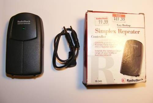
| #19-345 Simplex Repeater Controller Note that this box is incorrectly called the "Simplexor" by some folks - that name is trademarked by Zetron and used on their Model 19B (and information on that unit is on the Zetron page at this web site). |
|
|
|
Anybody have the Service Manual? We can scan one if necessary. |
|
|
User's Guide 162 kB PDF |
|
|
Operation. |
|
|
Features. |
|
|
Hints and Tips. |
|
|
Specifications. |
|
|
Power options. |
|
|
Parts list. |
|
|
Photo |
|
|
|
| General Guide to Scanning published by RadioShack, aimed at the PRO-series scanners. | |||||||||||||||||||||||||||||||
| Pro-43 Scanner The Pro-43 scanner (model number 200-0300) was introduced in 1992 and for a long time was their only portable scanner where the "UHF" band was 200-512 MHz instead of 400-512 MHz (they marketed the addition as adding military aircraft coverage), and "low band" was 30-54 MHz instead of 30-50 MHz. Yes, not only did it cover 6 meters but it also covers amateur 220-225 MHz right out of the box. And it doesn't need a special battery pack - you can use either penlight nicads or penlight alkaline batteries. And if you do put rechargeables in it, you will find a charger jack already installed in the side of the unit waiting for you! It was made by GRE for RS, and was before the days of CTCSS or DCS, alpha tags and trunking. This unit was the first portable triple conversion scanner from RS and the first to come with AM mode selectable on bands other than the aircraft band. By the way, the Motorola GP-300 handheld balistic nylon radio case is an absolutely perfect fit (anybody have the Moto part number? I'll add it here). |
|||||||||||||||||||||||||||||||
|
|
Owner's Manual 930 kB PDF | ||||||||||||||||||||||||||||||
|
|
Exploded View 17kb GIF file | ||||||||||||||||||||||||||||||
|
|
Parts List 28kb text file | ||||||||||||||||||||||||||||||
|
|
Service Manual 2.4 MB PDF | ||||||||||||||||||||||||||||||
|
|
Info Including a note on removing a capacitor to improve the audio. | ||||||||||||||||||||||||||||||
|
|
A Pro-43 modifications writeup by
Howard Bornstein This writeup includes adding coverage of the 824-851 MHz and 869-896 MHz bands. |
||||||||||||||||||||||||||||||
|
|
The early Pro-43s can be modified to receive 6-1000 MHz Al Mellon N8KLI figured out how. | ||||||||||||||||||||||||||||||
| Pro-2002 Scanner The Pro-2002 scanner (20-116) was one of the first decent programmable scanners. It uses the so-called "Motorola" antenna jack for the external antenna and the adapters are a little hard to find (RS does offer a Motorola-to-female-BNC adapter, part number 278-208, and your store can get it if they don't normally stock it). Some folks have ended up ignoring the stock antenna jack and adding a BNC next to it, or removing it outright and using the hole for a replacement BNC jack. The screw-in rod antenna uses a metric thread and as a replacement part is pure unobtanium in the USA. The 2002 handles 50 channels in low band (30-50 MHz), high band (138-174 MHz), aircraft (108-136 MHz) and UHF (410-512 MHz). As a scanner, it's nothing special, except that they are usually found in the $1-$25 price range, have a large, clear speaker, and the book is impossible to find, except here. If your local public service agencies run conventional (as opposed to trunked or P25 digital modulation), it's a good-sounding inexpensive programmable unit to park on some local channels. |
|||||||||||||||||||||||||||||||
|
|
Owner's Manual 997 kB PDF | ||||||||||||||||||||||||||||||
|
|
Service Manual 2.7 MB PDF This is actually the manual for a Handic (Sweden) 0050 scanner, which is supposedly a rebranded Pro-2002. As they say, it's better than nothing. |
||||||||||||||||||||||||||||||
| Pro-2003 Scanner # 20-9117 The PRO-2003 was the predecessor to the 2004-2005-2006 series of scanners and in late 1985-early 1986 was the top of the line and the price reflected that (and as a result it didn't sell very well), plus it scanned at a rate of only 8 channels per second where the competition did 15 to 16 per second. It offered 50 memory channels and covered low band (30-50 MHz or 66-88 MHz, depending on the country), 108-136 MHz AM Aircraft, 138-174 MHz (various), the 2m Amateur and high band, 148-174 commercial and public safety, 410-512 MHz (410-420 Government band, 440 MHz amateur band plus connercial), plus (and this was unusual) the FM broadcast band. The packaging was almost identical to the future PRO-2004, but the keyboard labeling was poor. |
|||||||||||||||||||||||||||||||
|
|
Owner's Manual 1.3 MB PDF | ||||||||||||||||||||||||||||||
|
|
Anybody have a PDF of the Service Manual?? | ||||||||||||||||||||||||||||||
| Pro-2004, Pro-2005 and Pro-2006 Scanners The 2004-2005-2006 series of scanners was the top-of-the line of the conventional-only scanners and were built for RS by GRE of Japan. Introduced in mid-late-1986. They covered 25-520 MHz continuous (10m, 6m, Aircraft, 2m, 220, 440 MHz amateur bands), 760-824 MHz (800 MHz repeater inputs), 851-869 MHz (repeater outputs), and 896-1300 MHz (900 MHz and 1.2 GHz amateur bands) in AM, NBFM and WBFM. Has 300 channels in 10 banks of 30, backed up by conventional 9 volt alkaline battery. Any channel can be designated the priority channel. "Sound Squelch" allows skipping dead carriers during search or scan. There is a tape recorder output jack on the back which provides 600 mV of audio at about 10,000 ohms impedance. There is a design oversight in all three models - the audio level of AM signals is somewhat below that of NBFM signals, requiring a different setting of the volume control. When scanning both AM and NBFM modes, one has to find a compromise position of the volume control. A trimpot or two in the audio mixer that combines the outputs of both detectors can be added, but a bit more care in the initial design would have precluded that necessity. One popular mod makes the unit portable by removing the power transformer and replacing it with a 12v gell-cell. You can charge it with a 12vDC wall-wart transformer (plugged into the existing +12vDC input jack). There are some cosmetic differences like the keyboard layout, but the internal electronics design is very similar across the three receivers. The major differences were physical packaging and the position of a few diodes in the configuration matrix plus:
|
|||||||||||||||||||||||||||||||
PRO-2038 Scanner #200-0413
This is a VHF and UHF scanner receiver that can operate on 13.8VDC or 120VAC with an
included AC adapter. It comes pre-programmed with hundreds of frequencies grouped by
service: police, fire/emergency, marine, air, and weather, as well as your own private
frequencies.
|
|
Exploded View 287 kB PDF |
|
|
Front Panel Features |
|
|
Front Panel Functions 254 kB PDF |
|
|
Basic Operations Guide Provided by Vince Poston |
|
|
Operations |
|
|
Preparation/Installation |
|
|
Special Features |
|
|
Specifications |
|
|
Troubleshooting |
|
|
Understanding Key Functions |
PRO-2067 500-Channel Mobile Trunk-Tracking Scanner
Owner's Manual 2.4 MB PDF
This is a VHF and UHF scanner receiver that can follow conversations on trunking systems.
It is designed to fit a standard DIN slot in a car dashboard. It covers the VHF and UHF
amateur and commercial bands.
PRO-94 1000-Channel Handheld Trunking Scanner
Owner's Manual 3.3 MB PDF
This is a VHF and UHF scanner receiver that can follow conversations on trunking systems.
It covers the VHF and UHF amateur and commercial bands.
Test Equipment |
|
|
|
22-305 LCD Frequency
Counter Owner's Manual 2.38 MB PDF donated by John Anderson WD8RTH This is a two-range hand-held frequency counter that is good from 1 MHz to 1 GHz, packaged in a VERY sturdy metal case with minimal controls: a power switch, a Hi-Z / 50 ohms switch, a range switch, a gate speed selector and a LCD backlight pushbutton. It's a lot better built than the average piece of RS equipment. 22-305 Frequency Counter Operation 46 kB PDF donated by "Sal C" - appears to be a faxback page that is no longer on the RS server. A viewable text file of the same document can be found here. 22-305 LCD Frequency Counter Service Manual 535 kB PDF donated by A. Nony Mous, but has a RadioAmateur.eu tagline. It's a pretty poor scan, but it's all we have. Additional info: Features Parts List Power Source Specifications |
|
|
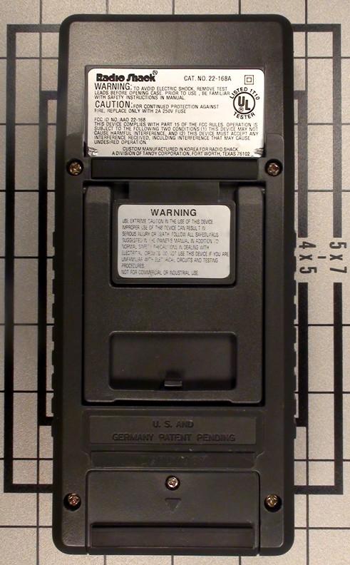
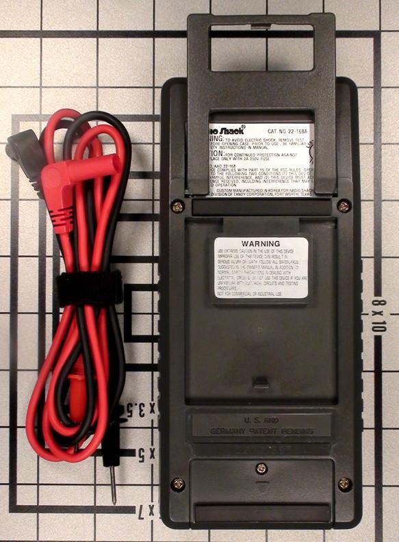
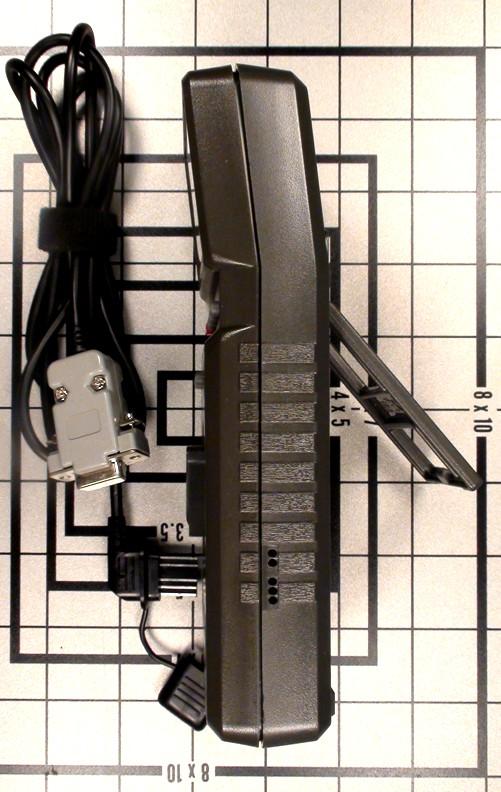
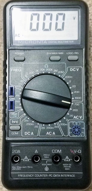
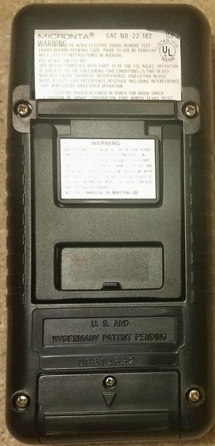
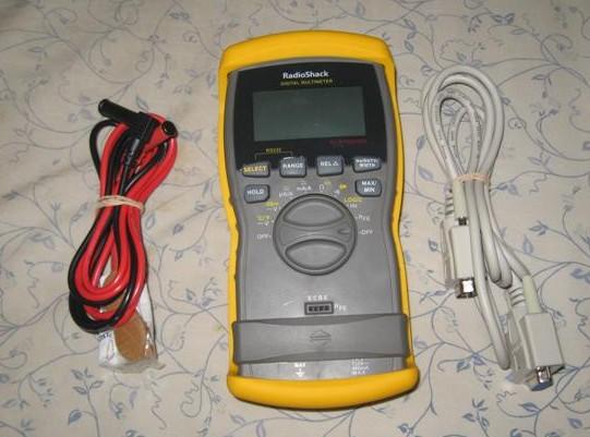
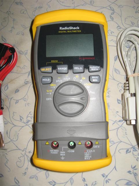
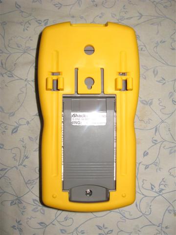
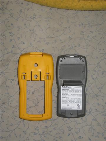
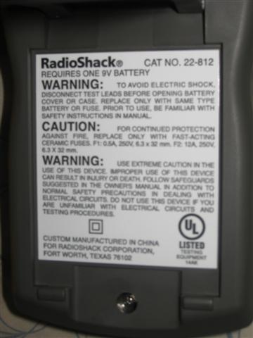
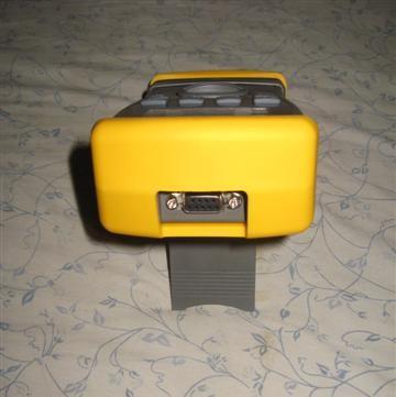
Serial DVMs - RS has sold several DVMs that had a serial port. Of the ones I am familiar
with the older unit is the 22-812 and the newer unit is a 22-168, later replaced with
the 22-168A (yes, a numerically lower model number on the newer unit). The 22-168 series
is made by Metex of Japan. There is also a 22-182 and a 22-805 but I do not know where
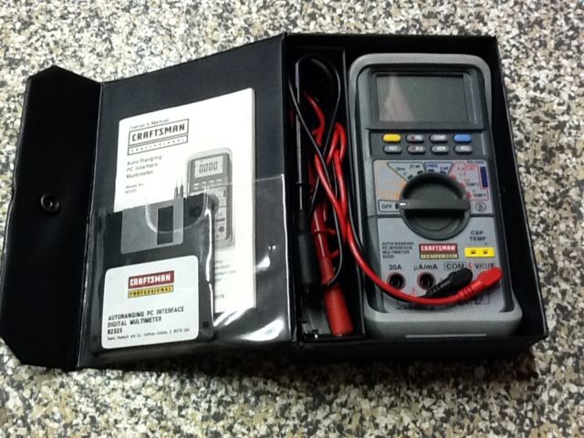
they fit into the marketing sequence. If you are going to be buying any computer-connected meter make sure that the serial port is isolated from the rest of the DMM via an infrared link in the DMM's case - this means there is no connection between the serial data pins and any meter input terminals. If you are going to use any battery operated serial meter to do some long-term data logging you might want to power it with a 9vDC wall wart transformer with an appropriate battery-snap-clip so that you aren't replacing the meters internal 9v battery on a regular basis. Or use 9 volts of "D" cells in a length of PVC water pipe. Like most DVMs all of these meters have internal fuses. You might want to keep an extra set in your meter case. It's interesting that Sears sold a similar unit: the "Craftsman Professional, PC interface auto-ranging digital multimeter 82324". Click here for a photo. Courtesy of Joseph Szczech Jr, K1IKE we have the Craftsman software.
|
|
|
Micronta 22-123 Variable DC Power
Supply 245 kB PDF 0-24V, 0-1A. Scanned by Skipp May, cleaned up by Bob WA1MIK |
|
|
Micronta 22-185A LCD Digital
Multimeter 1.2 MB PDF Scanned by Dave Childs, cleaned up by Bob WA1MIK |
|
|
Radio Shack 22-191 Digital Volt Meter schematic only 50 kB PDF |
|
|
Micronta 22-195 benchtop DVM (looks like a clone of my old HP) small file 2.78 MB PDF large file 4.58 MB PDF |
|
|
Archer 28-4013A VOM Manual
1.3 MB PDF donated by Dave Childs This was a kit. The assembly section of the manual has been eliminated. |
|
|
Model 277-1008 "Mini Audio Amplifier" - This is a single LM386-based audio test amplifier
unit that is VERY handy when debugging repeater controller interfacing problems or
IRLP node audio problems. The official RS users guide is
here as a 118 kB PDF. Thomas Myers N9LHK sent me a very good, well-lit closeup photograph of the schematic sticker that was in the "B" model units (they no longer do that). I played with and cleaned up the image a little using a couple of graphic programs. The final schematic of the "B" version is here as a 71 KB GIF image. Note that the capacitor values are expressed in a strange format: "16 10" is a 10 µF 16v unit, "10 100" is a 100 µF 10v unit, and "10 47" is a 47 µF 10v unit. If you examine the schematic you will notice that the unit has a design flaw due to the fact that it was designed to meet a sales price target. There is no input DC blocking capacitor, it has an input impedance of 5K Ohms, and may load down a high impedance source. The first part I fixed by adding a series cap to the test lead set, the second I will fix if I ever have to replace the input pot. I'll use a 100K or 500K pot, and add the DC blocking cap internally. The simplest way will be to use a 25µF nonpolarized ceramic chip cap with one end stuck into the solder pool at the top of the pot, and the wire from the "Input" jack soldered onto the other end. The "C" revision that is currently being sold has an additional 22 µF cap in series with a 100 ohm resistor between pins 1 and 8... this, according to the data sheet adjusts the audio gain. The next time I get inside mine I'll try it. If the 9v battery seems to die 'way too soon check for excessive leakage in the 47 µF 10v electrolytic cap that goes from pin 6 to pin 4 on the LM386 chip. The cap in my unit was leaking 19 to 20 ma worth... a new cap fixed it (the LM386 chip itself is spec'd for less than 5ma at idle). Here's the mod to add a normal / de-emphasis switch. The de-emphasis curve is dependent on the RC values - do not subsitute and use a 5% resistor and a close-tolerance capacitor. Many inexpensive caps are -60%/+100% tolerance, for this mod go out and buy a 5% cap. Adding the switch and the two parts allows you to monitor receiver discriminator ("flat audio") sources properly. Here's the LM386 data sheet (local copy) If you are going to build your own version of this unit a better choice is the LM4951 (and it has an optional mute/PTT input as well). You can build one into an old Motorola mobile speaker housing, and put the volume control and power switch into the side or back wall - or even into the center of the grille. |
Accessories and Other Products |
|
|
|
RadioShack "Amplified Mobile Extension Speaker" (model 21-541) - Schematic
Parts
List. This unit is a cheap knockoff of Motorola's "Power Voice" mobile speaker with an interesting design twist. It's designed for the situation where the speaker amplifier in a CB doesn't have enough power to be heard, for example in a pickup truck with the windows open. Obviously it's just as usable on ham radio as on CB. The interesting twist is that the DC power to the audio amplifier is controlled by a VOX-type of circuit. Motorola's design didn't need it. |
|
|
20-2006 telescoping antenna 35 kB PDF |
|
|
21-1384 External Speaker-Microphone 6.3 kB PDF (anyone have the schematic?) |
|
|
21-1897 2-Way Radio Hands-Free Headset 432 kB PDF A nice single-ear headset with a boom microphone with it's own VOX control, but no schematic or tech info is provided. |
|
|
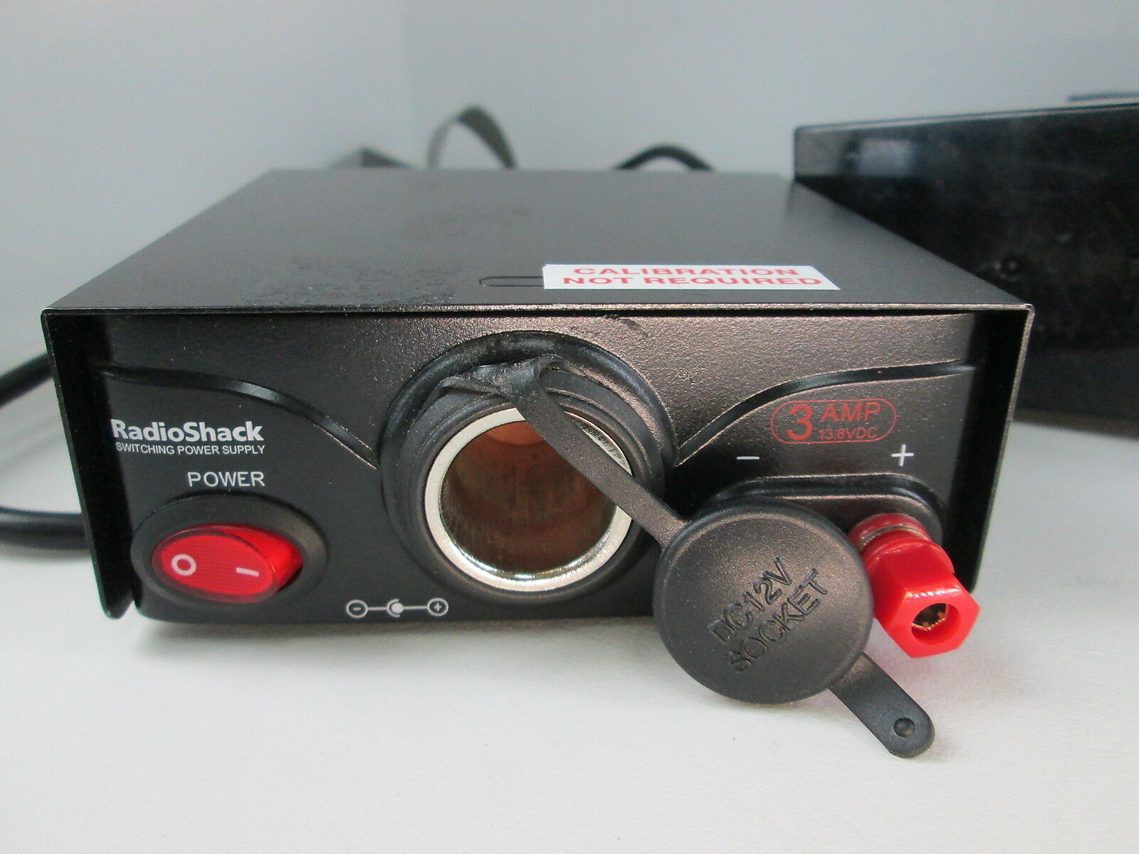
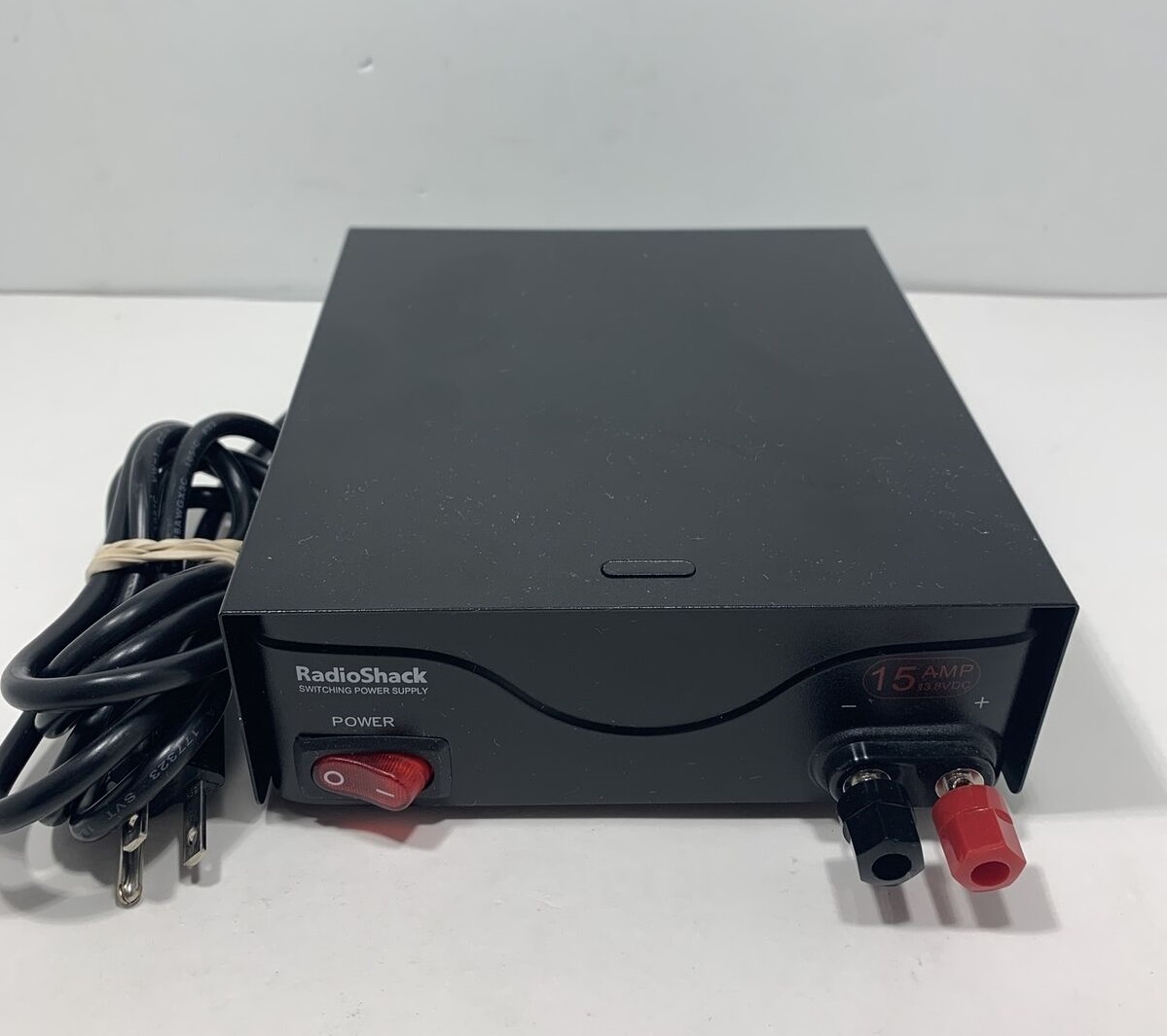
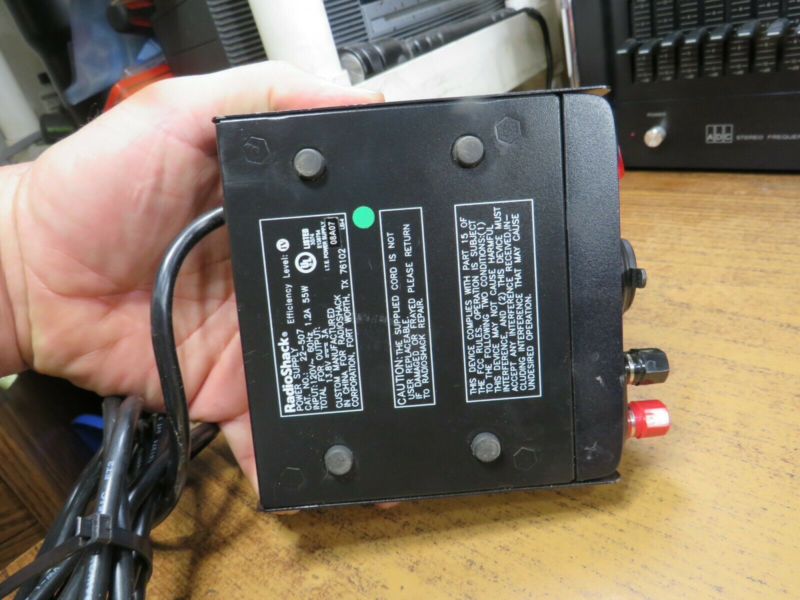
SAFETY ALERT On 02 July 2008, the US Consumer
Product Safety Commission (CPSC), in cooperation with RadioShack, announced a voluntary
recall of 13.8 V dc power supplies, catalog numbers 22-507 (22-507 front photo) and 22-508 front photo (a 15 amp version of the same unit but without the cigarette lighter plug) with date codes from 08A04 through 01A08, sold nationwide from October 2004 through January 2008. The catalog number and date code are located on the back or bottom of the power supply. The CPSC alert (that's a local copy, it was originally at http://www.cpsc.gov/cpscpub/prerel/prhtml08/08319.html) said that consumers should stop using these power supplies immediately, as the "power supplies are wired incorrectly, posing electrocution and fire hazards." The CPSC alert recommended that consumers unplug the recalled power supply immediately and take it to any RadioShack store for a free repair. The CPSC alert stated that 160,000 total units were mis-manufactured. Power supplies with a green dot on the product and the product's packaging were either built correctly or have already been repaired and are not included in the recall. Opening the unit up reveals that the power cord is connected to the circuit board with 1/4 inch push-on tabs, and that the board is labeled with "L" (for Line) and "N" (for Neutral). The production line incorrectly put the black wire on Neutral and the white wire on Line. The fix that was done by the local store was to unplug the 1/4 inch tabs and swap the black and white wires placing black on Line and white on Neutral. Interestingly, the bottom of the unit says that the power cord is not replaceable. They lie. Here's the paperwork packed with the 22-508 1.5mb PDF There is no technical info, no schematic, and as a result is pretty useless. Does anybody have a schematic of any revsision of the 22-507 or the 22-508? As long as you are inside the 22-507 or 22-508 power supply you will find there is enough room on the front panel for a set of Anderson Powerpoles. There is also extra space on the rear panel (in the corner opposite the power cord) to add a second set of PowerPoles. BTW, the Pyramid PSV40 series is the same unit with different cosmetics. The currently produced PSV40U deleted the cigarette lighter, and adds a USB charging jack, a voltage adjustment potentiometer and a 3 digit LED voltmeter. |
Weather Radios (or as some RadioShack literature calls them, WeatheRadios) |
|
|
Weather Radios, no matter who makes them, have two purposes. First, they are a
receiver preset to the NOAA Weather Radio (NWR) services frequencies, and they
receive regular, around-the-clock weather status and forecasts information.
Second, the newer ones are designed to respond to geographically-based alert
signals sent by the NOAA Weather Radio service. When the weather radio receives
an alert signal, it will sound an audible alarm to attract attention. The Weather Receivers come in three flavors: First, there are the plain monitor receivers that listen to the weather channels and has no warning mechanism at all. This is the same functionality as having the local weather channel programmed into an extra memory in your 2m handheld radio. Secondly there are the simple first generation alert receivers that decode the 1050 Hz alert tone. Thirdly, there are the second generation receivers that use a type of digital coding called Specific Area Message Encoding or SAME. The SAME system divides the United States into geographical weather areas and you program the reciever to respond to the geographic code (called a FIPS code) for your local area (or if you live near a boundary, you program in both codes), or if you want, you can add the codes for the areas surrounding the perimeter of your FIPS area. Most of the codes are aligned along county lines, but as we all know RF doesn't pay attention to political boundaries. The first weather channel allocated was 162.550 MHz, then a year or so later the politicos wised up and realized that you can't provide local weather info to the whole nation with just one radio channel. They added 162.400 and shortly there after added 162.475 MHz. Most second hand receivers that you find will be single channel (162.550), rarely two channel (162.550 and 162.400 MHz) and usually either three channel (162.550, 162.400 and 162.475 MHz), or seven channels. There is a lot more information on weather radios and the SAME system on this page. |
|
|
|
If anyone has info on other RS receivers such as the 12-093, 12-521, or 12-991 please send it in. As of the beginning of 2012 RS is selling Midland, Eton and Sangean radios on their web site. |
|
|
There is an article on interfacing a Reecom brand weather receiver on the Arcom page at this web site. The Reecom is a decent knockoff of the very desirable Radio Shack 12-250. |
|
|
#12-140 "Weatheradio Alert III" – This is an older three channel receiver. It is powered by a normal power cord and has a 9v battery pocket in the bottom of the case. |
|
|
#12-152A – This is another three channel synthesized receiver, despite the fact that it is labeled as "Crystal Controlled Weatheradio". It uses one 9 volt battery or an external 9v wall wart transformer. |
|
|
#12-154 – This is also a three channel radio with a 1050 Hz tone decoder. |
|
|
#12-240 "Weatheradio with Alert" Owner's Manual
139 kB PDF This unit is also a three channel unit, and decodes the 1050 Hz alert tone. It is powered by 120vAC. |
|
|
#12-241 "Desktop Weatheradio" Features, Power Sources, Operation, Specifications Manual 16 kB PDF This is a 3-channel receiver. |
|
|
#12-247B "Weatheradio Alert" This is a 7-channel SAME receiver, with the NOAA logo, powered by an AC cord but with a 9v battery compartment. The external antenna connector on the rear is an RCA jack. We don't have a PDF of the owners manual, does anybody? |
|
|
#12-248 "7 Channel Digital Pocket Weatheradio
Alert Manual" 480 kB PDF This unit receives all seven NOAA channels and decodes the 1050 Hz alert tone. |
|
|
#12-249 SAME Weather Receiver Owner's Manual
684 kB PDF Note that to receive multiple geographic areas (up to 15) you have to set the single/multiple switch on the bottom of the unit to the multiple position, otherwise it monitors position one no matter how many are programmed. Some of these radios have firmware that does not recognize the EOM signal. These have a fixed 5 minute message timeout. This unit has an external antenna jack, plus a 2-pin terminal strip (accessible from outside the case) for an external alarm. These terminals on the radio have a constant 1.2 VDC on them until an alert is received, at which point the voltage goes to 7.2 VDC, and remains there for the length of the alert, or until the alert is manually turned off. The 7.2 VDC only appears when an alert is sent by the National Weather Radio service and does not appear when conducting a self-test of the radio. The voltage is at a low current (originally designed to feed an X-10 Encoder, but very useful for other things). Don't plan on powering anything more energy intensive than a Solid State Relay, a switching transistor, or maybe the coil of a reed relay. Here's what the terminal strip was designed for. |
|
|
#12-250 SAME Weather Receiver Owner's Manual
466 kB PDF A stock photo of a 12-250 An updated version of the above receiver that supports a wider variety of alert codes and has the two pin terminal strip (see the 12-249 above for information on the terminal strip). If you are going to use an RS Weather receiver this is the one to look for (the 12-249 is your second choice). I'm told that there are at least two different revisions of the firmware in this unit, and that one does not respond to an EOM code - but that the built in 5 minute timer does re-mute the audio. |
|
|
#12-251 SAME Weather Receiver Owner's Manual
949 kB PDF
Photo A cost reduced unit that cut the geographical areas to two, and deleted the external alarm terminal strip. |
|
|
#12-255 SAME Weather Receiver We have no information on this unit. |
|
|
#12-257 SAME Weather Receiver We have no information on this unit (yet) other than the #12-257 SAME Weather Receiver Owner's Manual 118 kB PDF This is a pocket unit not much larger than an FRS radio, with a cute feature: it has a vibrator mode (like a pager or cellphone) that can be set to trigger during warnings or alerts. You could replace the motor with a relay coil... |
|
|
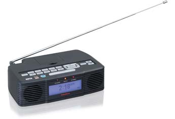
#12-260 SAME Weather Receiver and alarm clock As of April 2009 this is a current product, and is sold as a bedside radio/alarm clock. The official 12-260 Bedside Weather Radio Owner's Manual can be found here. We have no technical data on this other than the advertisement on the RS web site, which by the way says it has a scan function in case the local weather transmitter goes off the air. The photo shows only one LED indicator. The RS web site does not have a #12-260 Support Page, but courtesy of Robert Stiles we have a PDF of the owners manual: high resolution (2.8 MB) and a slightly lower resolution (530 KB). There is no tech info in the owner's manual other than a page of specifications. |
|
|
#12-261 SAME Weather Receiver 2003
vintage Owner's Manual 2004 vintage
Owners Manual This unit has a 9 volt battery pocket in the bottom of the case, or can use an external 9vDC wall wart transformer (the book says the battery is for backup purposes). It also has an external antenna jack, plus a 2-pin terminal strip accessible from outside the case (like the 12-249) for an external alarm. Here's what the terminal strip was designed for. There is an interfacing article below on this unit. Photo Parts List |
|
|
#12-519 All-Hazards Weather Alert Clock Radio with Skywarn Model 732R
Owner's Manual 1.15 MB PDF file
Programming Addendum 105 kB PDF
Photo This is a multifunctional design that is not really appropriate for a mountaintop repeater SAME alert - this is intended as a bedside clock radio with a bonus - it is an alarm clock, an AM/FM stereo radio, a weather radio AND a 20 channel scanning 2m or 440 MHz receiver! The owners manual calls it the "Skywarn band" and the owners manual says it covers 144.39-148.00 and 441.0-452.0, but in some areas the Skywarn folks also use GMRS channels in the 462 MHz region and this radio will not hear them. The unit has a extendible rod antenna AND a BNC antenna jack on it for the external antenna. The wall wart is 12vDC at 400ma and the connector is tip positive. There is a pocket in the unit for six penlight cells ("AA" size) for backup (you can also use Ni-MH rechargeable batteries, but you must remember to flip the switch inside the battery compartment from ALK (alkaline) to RCH (rechargeable). There is a 2-pin terminal strip accessible from outside the case (like the 12-249) for an external alarm (like a pillow shaker). The speakers are small and tinny, the only other complaint I have heard is that the blue display is a little bright at night even at "low" setting (there is no OFF selection). |
|
|
#120-1455 "Weatheradio 3" Operation Manual
16 kB PDF This AM/FM/Weather radio boasts a mechanical 120VAC clock. |
|
|
#120-1458 "Weatheradio 6" Operation Manual
25 kB PDF This AM/FM/Weather radio also has a mechanical 120VAC clock. |
| Weather Receiver Interfacing Articles | ||
| These articles cover only the interfacing aspects. At some sites the Weather Radio may suffer from RF overload, which may require other methods to resolve, up to and including repackaging the Weather Radio receiver in a shielded box and feeding it with an outside antenna. Extreme situations may require a cavity filter between the antenna and the receiver-in-a-box. One acquaintance ended up tracing the circuitry in a RadioShack receiver and completely disconnecting the receiver section and feeding a MICOR receiver into the RS decoder. | ||
| Depending on your circumstances you may want to have your repeater
transmit in response to a "Watch" or to a "Warning" or to both.
The NWS describes the difference as: 1) A watch alerts you to potential severe weather approaching your area. It doesn't mean severe weather will occur, but that the right conditions exist which could lead to severe storms. You should be prepared for deteriorating weather 2) A warning states the severe weather is imminent or present in your vicinity. You should immediately take precautions to protect yourself and your family. |
||
|
|
Interfacing the Weather Radio to a repeater controller Scott Zimmerman N3XCC connected a #12-251 Weather Radio to an Arcom repeater controller, but the 12-249, 12-250 and similar receivers (like the Reecom) would work just as well. This article describes the hardware interface only. The outputs for Statement, Watch, Warning and COS connect to alarm inputs on the RC210, and the receiver reset input is connected to a digital output (and is used to acknowledge or clear the Statement, Watch and Warning alerts). See the "More than three ports?" article on the Arcom page at this site for a method of interfacing a Weather Radio without using one of the three ports on a RC-210 or one of the 8 ports on an RC-810. |
|
|
Another take on interfacing a Weather Radio to a repeater controller Kevin Thomas W6KGT (ex-KB5ZVK) uses two opto-isolators and two relays to connected any Weather Radio to a CAT-1000 repeater controller. The design is generic and can be used on any brand of repeater controller. A digital output on the controller programmed for pulse mode could drive a reed relay whose contacts are wired across the reset button in the weather receiver. |
|
|
A third take on interfacing the Weather Radio to a repeater controller Fred Vobbe W8HDU connected a #12-249 Weather Radio to a Link brand repeater controller. This article gives an overview, a list of links to geographic zones, a codes table, describes the hardware interface he built, and covers the Link RLC-series controller programming in detail. The 12-250 and 12-251 and similar Midland receivers would interface very similarly. This is a local copy of Fred's original article; the original link is gone now. |
|
|
Yet another take on interfacing a Weather Radio to a repeater controller KF4PXZ connected a #12-250 to an Arcom RC-210 repeater controller. This short article shows where to pick up the decode alert logic line and the audio. The 12-249 and 12-251 would interface very similarly. |
|
|
An Automated Repeater SAME
Weather Alert by Stewart Radinowitz KE5UT This writeup
uses a 12-261 WeatheRadio. A stock photo of a
12-261 This writeup describes how to use an inxpensive VOX unit to generate the Alert or Warning signal for the COR lead of the radio port on the repeater controller. The technique could be used on any receiver (RS or otherwise), just remember that the properly designed SAME radios (i.e. one that uses the audio "turn off" code) will forward the entire alert (no matter how long), whereas the Midlands use a shutoff timer. |
| Weather Receiver Test Files | ||
|---|---|---|
|
Once you have the weather receiver interfaced, you need to test it. Here are some
test files. It will take careful level setting to avoid trashing the digital data.
Kindly do it on a channel not in use in your area, with a shielded cable between
your generator and your weather receiver, and with the lowest power - you don't
want to panic your neighbors. The digtial coding of the SAME data burst has the Julian day (i.e. day 001 to day 365) and the location embeded into the data burst. Some decoders do not look at either, some do not look at the day (i.e. if it's outside 24 hours of the time the box says it is), some do not look at the location... they figure that if the receiver can hear it then it's worth alerting. The SAME system is set up so that an alert issued for California won't trigger an alert for a box in Colorado. One rule of thumb is that if you don't have to set the date on the receiver (i.e. most low end receivers) then it ignores the date. So if you have a well designed box these samples may not work. The first three samples below were download from the GORMAN REDLICH web site, specifically the EAS test messages page. |
||
|
|
An MP3 recording of a Required Weekly Test 288 KB MP3 file |
|
|
An MP3 recording of a Required Monthly Test 396 KB MP3 file |
|
|
An MP3 recording of a Tornado Warning 386 KB MP3 file |
|
|
Thunder Eagle has a few
at their web site (off site link) Note that you may have to add a specific location code (a FIPS code) mentioned on the web page to your receiver before these will work. |
Back to the top of the page
Back to Home
This page initially created 14-Oct-2004.
RadioShack, Micronta, Realistic, Archer and probably others are legal trade marks / service marks of Tandy Corp and no infringement is intended. The amateur radio equipment manual PDFs are here due to the interest expressed in the Tandy/RadioShack-made equipment by the amateur radio community and the fact that they are no longer available on the public RS web site. The scanner manuals are here because most are not available from anywhere else and in any form.
This web page, this web site, the information presented in and on its pages and in these modifications and conversions is © Copyrighted 1995 and (date of last update) by Kevin Custer W3KKC and multiple originating authors. All Rights Reserved, including that of paper and web publication elsewhere.