Back to Home
Information from Kevin Thomas W5KGT (ex-KB5ZVK)
HTML'd by Mike Morris WA6ILQ

|
Up one level Back to Home |
A Smple Interface between a Weather Receiver and a Repeater Controller
Information from Kevin Thomas W5KGT (ex-KB5ZVK) HTML'd by Mike Morris WA6ILQ |

|
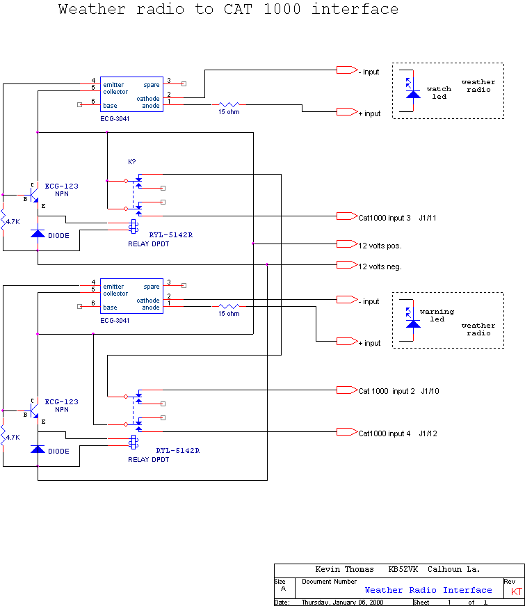
This interface diagram shows the connection of a SAME-encoded weather radio to a repeater controller. While I used a Radio Shack receiver and a CAT-1000 controller the interface is generic and will work with other brands of receiver and controller. Not shown is the audio connection from the top of the receiver volume control through a DC blocking capacitor to the audio input of the controller (the cap may not be needed if there is one already inside your controller). You will want to use shielded cable for the audio connection.
Any brand controller can be used as long as it has digital inputs that can trigger actions. The top relay closes when the "Watch" LED comes on and applies +12v to the #3 alarm pin, the bottom one closes when a "Warning" comes on and applies power to the #4 pin. Suitable programming handles the rest.
+12vDC from the weather receiver is applied to the #2 digital input pin through the normally closed relay contacts during normal conditions. If this goes away without #3 or #4 activating the controller can announce a weather receiver failure.
The top relay could be a single-pole, double-throw, instead of a double-pole, double-throw. I used what was in the junk box.

|
Back to the top of the page
Up one level
Back to Home
Hardware design and schematic © 2002 by Kevin Thomas W5KGT (ex-KB5ZVK)
Artistic layout and hand-coded HTML © Copyright 2006 and date of
last update by repeater-builder.com.
This web page, this web site, the information presented in and on its pages and in these modifications and conversions is © Copyrighted 1995 and (date of last update) by Kevin Custer W3KKC and multiple originating authors. All Rights Reserved, including that of paper and web publication elsewhere.