Note that in Motorola's product line terminology you have either a "mobile" or a "station",
and the latter term is used for both base stations and repeaters.
How to identify
your MICOR
Mobiles are on the top, scroll down for stations
Note that DVP (secure) stations frequently substituted an "X" for
the center letter in the suffix (i.e. a C74RCB became a C74RXB).
Here's a simpler MICOR
Mobile only identification table
Jump to:
Generic MICOR (both Mobile and Station) Read this section
first
Generic Station Information
Low- and Mid-Band Station
High-Band Station
UHF Station
Generic Mobile Information
Low-Band Mobile
High-Band Mobile
UHF Mobile
Channel Element Info
220 MHz Conversion
Custom Built Repeaters
Other Information
Systems 90 Information
Packet
Images and PDF Files
Information Relevant to Both MICOR Mobile and
Station:
 |
The actual patent for the MICOR Squelch
chip: M6709, MC6709, SC6709, M7716 640 kB PDF
Several squelch articles below refer to this document. |
|
The MICOR
Squelch By Kevin Custer W3KKC
An Explanation of the MICOR Bi-Level Squelch. |
|
Additional Info about The MICOR
Squelch Chip By Robert W. Meister WA1MIK
Testing and examination of the MICOR M6709 IC. |
|
MICOR based squelch
circuit A SEITS article |
|
Explanation of Reverse Burst and "AND"
Squelch By Kevin Custer W3KKC |
|
Pre-emphasis, de-emphasis,
clipping, and audio quality in the MICOR By Paul Sexauer K3VIX |
|
MICOR Muteboard, muting audio filter
amplifier By Kevin Custer W3KKC |
|
Modification of the MICOR PL
Encoder By Kevin Custer W3KKC
In some situations you want to disable the reverse-burst capability. |
|
COS Logic Level Inverter By Kevin
Custer W3KKC
A simple circuit to make a positive logic COS from the audio-squelch board for those controllers
that require it. |
|
MICOR discriminator
buffer amplifier Great for NHRC, MCC, and other newer style controllers that
mute and have de-emphasis built in |
|
MICOR PL Filter By Kevin Custer
W3KKC |
|
MICOR PL Filter
Modification By Kevin Custer W3KKC |
|
An "S-Meter" for the MICOR Receiver
While this circuit was originally developed to allow a repeater receiver to drive an analog
input of an ACC repeater controller there is no reason that it couldn't drive a different
brand of repeater controller or even a meter... |
|
TLN4310B and TLN4622B Audio
Squelch board - full info (3 pages), 265 kB PDF scan courtesy Eric Lemmon WB6FLY
TLN4310B-2 schematic only (horizontal, for viewing on your
screen) TLN4310B-2 schematic only
(vertical, for printing)
You will probably want to print the schematic on legal paper, as it is an extended length
diagram. If you are going to do any bench work, I'd suggest printing it on 11x17 paper. |
|
Information on MICOR Channel
Elements By M. Scott Zimmerman |
|
Modification of the MICOR "Sensitron"
450-470 MHz Receiver RF and IF Board for use in the UHF ham band By Kevin Custer
W3KKC
A step-by-step procedure on how to modify a TRE1203A (or B) or TLE8032A (or B) 450-470 MHz
receiver board to operate properly below about 445 MHz. |
|
Motorola made some special order stations in the 440-450 MHz range - either
for well-funded amateur groups, or for the European market (the UHF commercial band in most of
Europe starts at 440 MHz instead of 450 MHz).
Here's the factory documentation on such a
radio. 65 kB PDF donated by Tim Sawyer WD6AWP
The three-page writeup is an addendum to the standard manual and covers modifications to the
TRE1241A receiver and the TLE1853A exciter, plus a few other notes. |
Non-Band-Specific Station Information:
Station Power Supplies:
Low-Band MICOR Station:
Notes:
1) The low-band MICORs came in four ranges, commonly called "splits": 25-30 MHz (very, very rare),
30-36 MHz, 36-42 MHz, and 42-50 MHz. The four articles below are all oriented to the 42-50 MHz
radios. If anyone would like to do a 30-36 MHz to 10 meters conversion article, please let us
know.
2) The low-band receiver is a TLB6851A (25-30 MHz), TLB6852A (30-36 MHz), TLB6853A (36-42 MHz),
or TLB6854A (42-50 MHz). Later versions would have had a different trailing letter.
3) Motorola offered a noise blanker option on low-band mobile radios (marketing called it an
"extender"). That receiver was the TLB6861A, TLB6862A, TLB6863A and TLB6864A series (the last
digit indicated the split, just like the TLB685x series).
4) The TLB685x and TLB686x receivers all have a 5.26 MHz intermediate frequency (IF). The TLB696x
receivers have a 5.36 MHz IF, usually used only in a second receiver situation or on special
order.
5) The 25-30 MHz receiver used an x2 multiplier and high side injection, the 30-36 MHz and 36-42
MHz receivers used x3 and high-side injection, and the 42-50 receiver used x3 and low-side
injection. All of the low-band receivers used the 3-pin K1003 channel element, none have AFC
(Automatic Frequency Control) and the element doesn't have an AFC input pin.
6) The low-band and mid-band stations use a TRN6007A audio-squelch board and it is different
from the TRN6006A board used in the high-band and UHF stations. The difference is two capacitors
(C210 and C216) in the audio path and they are easily changed in the field.
Mid-Band MICOR Station:
The mid-band receiver is a TLC6112A or B, and is identical to the low-band receiver
except for frequency range and multiplier (times 6, high side injection). These were
commonly used as link receivers in paging systems. The crystal filters are also
optimized for the digital modulation data used for paging. These can be converted
to low-band receivers if you replace some coils and capacitors.
High Band MICOR Station:
(220 MHz mods are in the 220 section below)
The high band station power amplifier requires about 200mW for full output. Other
web sites and books say that it takes about twice that. Here's why: The high band
station exciter is specified for 400mW of power output, however, in a stock station
there is always a band-pass filter between the exciter output and the amplifier input.
These filters have about 2 to 3 dB loss, so the actual drive reaching the amplifier
is about 200 mW.
The fastest way to identify the split of your new-to-you Micor is to look at the receiver...
a TLD8271 is a 132 to 142 MHz, a TLD8272 is a 142 to 150 MHz, a TLD8273 is a 150.8 to 162 MHz and a TLD8274 is a 162 to 174 MHz unit.
|
Comprehensive conversion of the MICOR
Compa-Station base/repeater station By Kevin Custer W3KKC |
|
Comprehensive Description of the MICOR "Sensitron"
Hi-band Receiver By Kevin Custer W3KKC |
|
Conversion of the MICOR "Sensitron" High-band
Receiver to the 2M Ham Band By Kevin Custer W3KKC |
|
Now available: 132-150.8 MHz
helical resonator coils By Kevin Custer W3KKC
Get a real 2 meter front-end for your MICOR receiver! |
|
Modification of the MICOR Exciter
By Kevin Custer W3KKC |
|
VHF MICOR PM to FM Exciter
Modification By Kevin Custer W3KKC
Convert your PM exciter to True FM! |
|
VHF MICOR tuning instructions By
Kevin Custer W3KKC |
|
Retuning the VHF MICOR Bandpass
Filter By Kevin Custer W3KKC |
|
A Conversion of a high
band MICOR Intermittent Station to a Repeater 4.2 MB PDF By Lawrence Glaister VE7IT |
|
Converting a high band PURC Station
to a Repeater By Matt Krick K3MK |
|
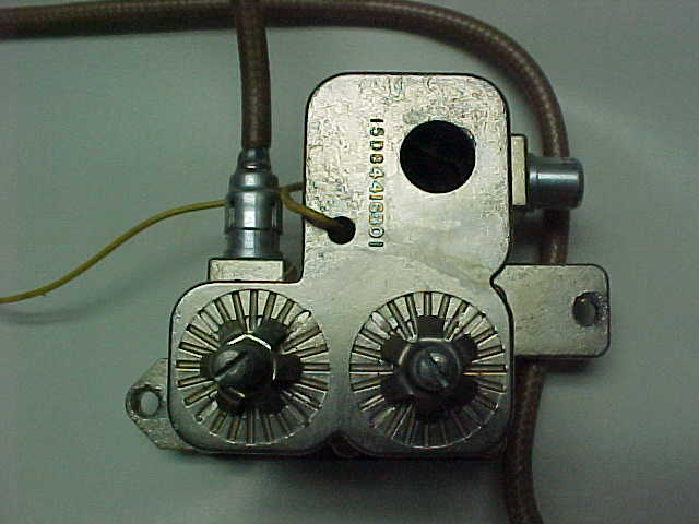
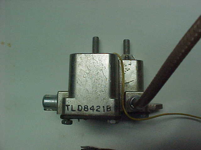
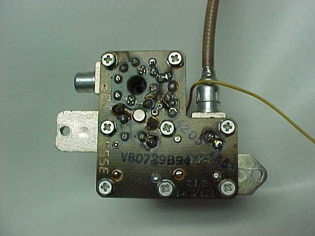
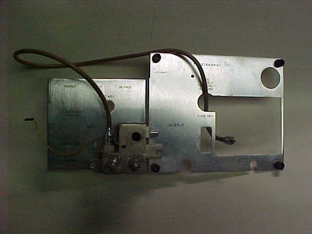
Documentation on
the high band MICOR Preamp model TLD8421A, TLD8421B, TLD8422A or TLD8422B 917 kB PDF
Donated by Eric Lemmon WB6FLY
Photos by Tony Faiola K3WX:
photo 1
photo 2
photo 3
photo 4 (shows mounting bracket used to
mount the preamp on the back of a Spectra Tac or Aux Receiver chassis)
(the 15D number visible in the first photo is the casting number, not the preamp part number)
Note that if you need a preamp and can't find one that
AngleLinear sells a very nice drop-in preamp, and a
mobile mounting bracket is available. |
|
Conversion of the TLD8422 high-band
factory preamp to the 2M ham band By Kevin Custer W3KKC |
|
MICOR High Band Service Sheet
Pg 1 This is page 1 of Moto manual 6881101E02-M. 2.2 MB PDF Donated by Eric
Lemmon WB6FLY
MICOR High Band Service Sheet
Pg 2 This is page 2 of the above. 844 kB PDF |
|
TLB6310A or TLD6340A
Crystal Filter and TLN5120 Installation Kit documentation 327 kB PDF
|
 |
Here's how to get the TLN5979A (DVP) backplane working without the DVP modules,
courtesy of Eric WB6FLY:
- Remove all jumpers EXCEPT 2, 4, 5, and 7. JU4 is a diode, with the cathode bar on top.
- On Slot 10 for the Code Detect module, jumper pin 7 to pin 15, and jumper pin 10 to pin 17.
- Use ONLY the 5970 SCM.
- Remove all modules except the SCM, Squelch Gate, and Timeout Timer.
Make certain the station works properly before connecting an outboard controller. |
UHF MICOR Station:
Information relevant to MICOR Mobiles
being converted to Repeater or Link duty:
Notes:
1) The MICOR mobile chassis has a heat sink rated at only 35 watts - yes, that fact is in
the MICOR mobile manual. Therefore radios higher than 45 watts are best left in mobile service.
2) The VHF MICOR transmitter power amplifier stages use PNP transistors where the UHF radio uses
NPN in the same area. Be careful when you do a rebuild that you have the right parts !!!
3) The normal mounting of a MICOR mobile has the radio mounted essentially upside down (the circuit
boards are mounted in the top of the case facing downward). As such the control connector pinout
is not what you would expect. Here is a drawing of
the pinout viewed from outside the radio, looking at the front.
Generic Mobile Information:
Low-band MICOR Mobile:
Notes:
1) The low-band MICORs came in four ranges: 25-30 MHz, 30-36 MHz, 36-42 MHz, and 42-50 MHz.
2) The low-band receiver part numbers are: TLB5851A and TLB5851B for 25-30 MHz (very, very rare),
TLB5852A and TLB5852B for 30-36 MHz, TLB5853A and TLB5853B for 36-42 MHz, and TLB5854A and
TLB5854B for 42-50 MHz. On all of them the IF is 5.26 MHz, or 5.36 MHz on special order.
3) The 25-30 MHz receiver used a x2 multiplier and high-side injection, the 30-36 MHz and 36-42 MHz
receiver used x3 and high-side injection, and the 42-50 MHz receiver used x3 and low-side
injection.
High-band MICOR Mobile:
(220 MHz mods are in the 220 section below)
See the station section for a breakdown on MICOR VHF (high band) receivers.
UHF MICOR Mobile:
Notes:
1) The UHF receiver is a TRE120nA or B (where "n" is 1 to 5), and the IF is 11.7 MHz, or 11.8 MHz
if needed to avoid mixes.
2) The "n" is "1" for 406-420 MHz, "2" for 420-450 MHz, "3" for 450-470 MHz, "4" for 470-494 MHz,
and "5" for 494-512 MHz.
3) All UHF receivers use an x24 multiplier. The high-side versus low-side injection decision was
dependent on several parameters; read the first article below for the details.
Custom Modifications, Conversions and Parts
Suppliers for MICOR Mobiles and Stations:
Channel Element Info:
220 MHz Modifications for the MICOR High-Band
Radio:
Packet Modifications for the MICOR:
Other information relating to the
Motorola MICOR:
Systems 90 Information:
Manuals in this section courtesy of Paul Fraas KDØCST, and were scanned and PDF'd by Eric
Lemmon WB6FLY
Scanned Images and
PDF Files:
The full manuals have model charts, installation instructions, circuit descriptions, parts
lists, board X-ray views, schematics, and the various accessories. The individual module
scans were often extracted from these full manuals. Assemblies that were common among
different bands can often be found in these full manuals
|
UHF Mobile
Instruction Manual 6881015E70-H 14.6 MB PDF file courtesy of Eric Lemmon WB6FLY |
|
The Base and
Repeater Control and Applications Manual 6881025E60-F 12.4 MB PDF file courtesy
of Eric Lemmon WB6FLY. Several revisions can be found below, courtesy of Eric WB6FLY. |
|
UHF Station
RF Manual 6881025E50-H 11.1 MB PDF file courtesy of Eric Lemmon WB6FLY |
|
Community Repeater
Station Supplement 6881025E55-B 5.9 MB PDF file courtesy of Eric Lemmon WB6FLY |
|
PURC Control and
Applications Manual 6881060E70-B 13.5 MB PDF file courtesy of Eric Lemmon WB6FLY |
|
VHF-hi DVP Station Manual
6881036E40-B 18 MB PDF
This manual includes the TLN5979A backplane. The full manual has been broken up into three
smaller sections:
- Pages
1-122 (7.8 MB): Model Charts, Description, Installation, Cabinetry, Station Maintenance,
Antenna Switch (Relay), T1480 Series Duplexers, Station Metering & Intercom, Transmitter
Interconnect Board, True-FM Exciter, 90/100/110w PA, 60w PA, Power Control Board, PL Encoder,
TX Hardware Kits, PL Inhibit Cable Kits, Unified Chassis Receiver Interconnect Board,
Sensitron Receiver RF & IF Board.
- Pages
123-165 (5.3 MB): Audio & Squelch Board, Audio Power Amplifier, PL Decoder, RF
Preamplifier, Receiver Hardware Kits, Power Supply, DVP and Tone Remote Control, Unified
Remote control Chassis, RF Intercabling, Station Control Module, Line Driver Modules, Guard
Tone Decoder Modules.
- Pages
166-187 (4.9 MB): Voice Protection Modules, Code Processor Module, Code Detect Module,
F1 Tone Decoder Module, F2 Tone Decoder Module, DVP Control Module (Code Select Module),
Four Frequency Control Module, Squelch Gate Module, CMOS Time0Out Timer, Line Interface
Module, Options Decoder Modules.
|
|
250/375 Watt 136-174 MHz Upright Base and Repeater (RT) Station Documentation
for the B83RCB and B93RCB stations. The Power Supplies section is from a 330 Watt 25-50 MHz
B91RCB manual.
|
|
Station Audio and Squelch
board 2.5 MB PDF
X-ray view, waveforms, schematic (TRN6006A, TRN6007A) |
|
How can you tell at a glance which A/S board you have? The Station A/S boards
have a line level pot on them and only uses one of the two mute signals to mute the speaker audio.
See this article for a way to utilize the second mute
signal for better speaker audio muting. The Mobile A/S board has no such pot and uses both of
the mute signals to mute the speaker audio completely. |
|
Mobile Audio and Squelch Board
layout 157 kB |
|
Mobile Audio and Squelch Board
schematic 166 kB
Mobile Audio and Squelch board (TLN4310B) |
|
Mobile Audio and Squelch
Board 2.4 MB PDF
X-ray view, waveforms, schematic (TLN4310B) from VHF-hi manual. |
|
Mobile Control Board 1.7
MB PDF
X-ray view, schematic, point-to-point wiring diagram (TLN4291B, TLN4292B) from VHF-hi manual. |
|
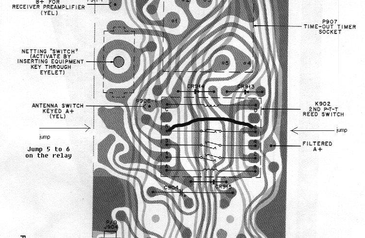
Mobile Radio Interconnect Board relay
area 118 kB |
|
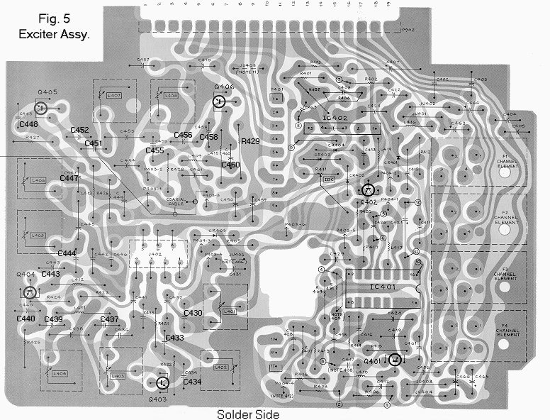
VHF-hi Exciter Board - A
version 3.5 MB PDF
X-ray view, waveforms, schematic (TLD5131A, TLD5132A, TLD5371A, TLD5362A) from VHF-hi manual.
PM exciter with FM input for DPL modulation. Uses 4-pin channel elements. |
|
VHF-hi Exciter Board - B
version 2.7 MB PDF
X-ray view, waveforms, schematic (TLD8261B, TLD8262B, TLD4081A, TLD4082A) from VHF-hi manual.
PM exciter. Uses 3-pin channel elements. |
|
VHF-hi Exciter Board
layout 157 kB |
|
VHF-hi 1-4ch Receiver and IF
Board 2.2 MB PDF
X-ray view, schematic (TLD8271B, TLD8272B, TLD8273B, TLD8274B) from VHF-hi manual. |
|
VHF-hi 5-8ch Receiver and IF
Board 3.8 MB PDF
X-ray view, schematic (TLD4071B, TLD4072B, TL4073B, TLD4074B) from VHF-hi manual. This board
also holds the transmit channel elements for channels 5-8. |
|
VHF-hi Mobile Wiring
Diagram 85 kB PDF |
|
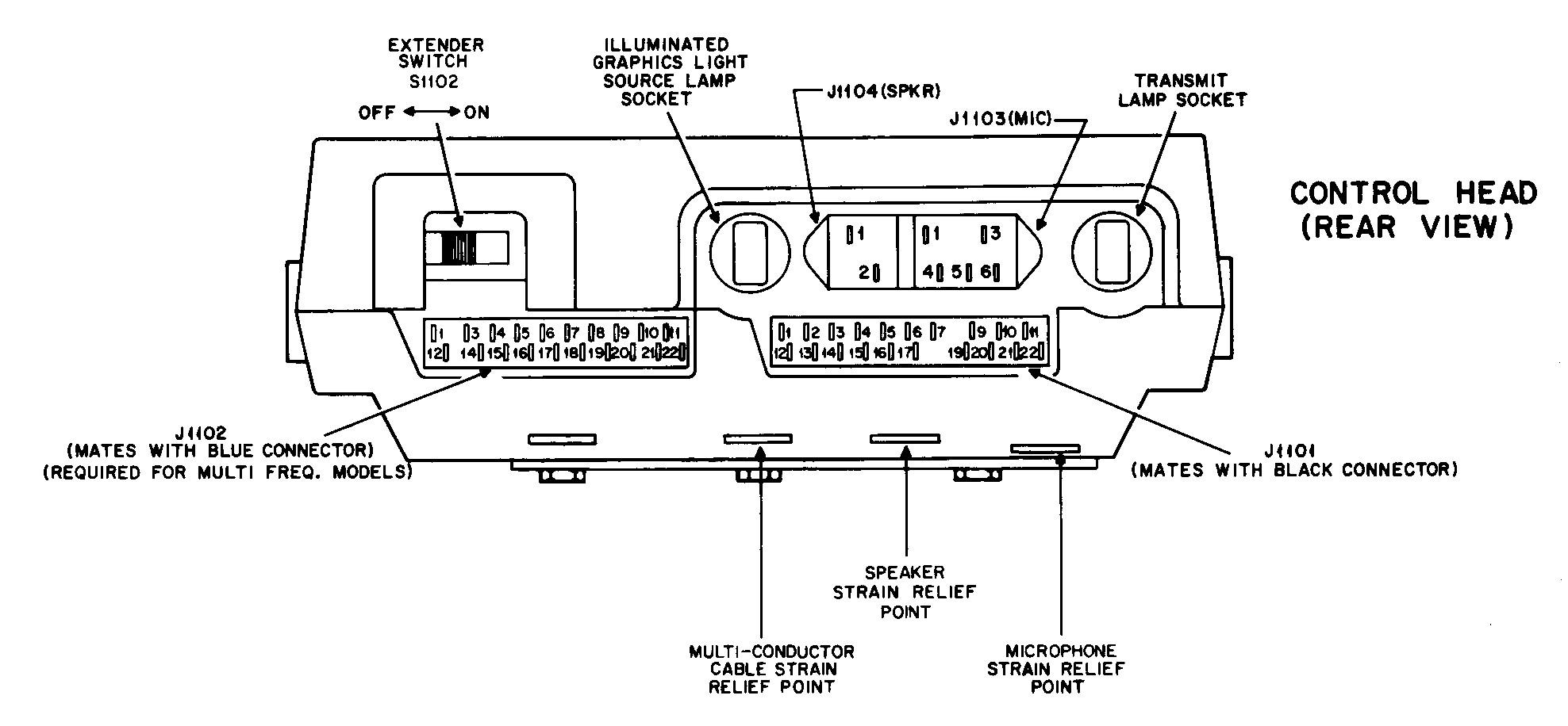
Rear view of the Mobile Control
Head 171 kB
|
|
Mobile Control Head
schematic 77 kB |
|
Palm Microphone TMN6054A
documentation 130 kB PDF including schematic
This same mobile microphone was used on the Mitrek. Click
here for a better scan (486 kB PDF) |
|
Station Control Module
for Securenet stations 1 MB PDF file courtesy of WA3WOM |
|
TLN4293B PL Encoder Module 1.5
MB PDF file courtesy of Bob WA1MIK |
|
TLN5731A PL Encoder Module 1.3
MB PDF file courtesy of Bob WA1MIK |
|
TLN5970A Station Control Module 1.55
MB PDF file courtesy of Kevin W3KKC and Bob WA1MIK |
|
QLN2812A Station Identifier Field Modification
Kit 1.2 MB PDF file provided by John Gilbert KA4JMC |
|
TLN1552A
Station Metering and Intercom Kit Manual 6881018E26-D 825 kB PDF file courtesy
of Eric Lemmon WB6FLY |
|
TLN5167A
Intercom, TLN5900 and TLN5993 Station Metering Kit, and TLN1859 and TLN1887 Metering
and Intercom Kits Manual 6881033E28-F 1.6 MB PDF file courtesy of Eric
Lemmon WB6FLY |
|
Base Station Accessories (Multiple
Tone PL Options) Manual 6881106E30-B 4.0 MB PDF file courtesy of Eric Lemmon WB6FLY |
MICOR VHF-hi Exciter transmit frequency spacing:
Bob Swoger, K9WVY points out that the Motorola manual
is in error when it states the High Band MICOR Mobile has a transmitter spread
of only 1.5 MHz. That is what the marketing group told the sales force. Actually,
the transmitter spread is 3 MHz on the standard production radio. The designer
of the first MICOR HB exciter was Jim Cox, a non-ham and laid off shortly after
the MICOR shipped in 1970 due to the fact that he was the oldest and losing his
hair. That first exciter board was single sided and had grounding problems due
to not enough copper foil. This was a problem with the early PC board layout
people. They wanted to start with a non copper clad board and add copper.
Engineers wanted them to start with a double sided copper clad board and remove
copper. Jim's board indeed was only 1.5 MHz wide. Soon after another engineer
named Don Nicklos (spelling?) made a double sided board that solved a lot of
problems with proper grounding. Don told me the new board could easily do 2 MHz
and more. I checked it out and found it could do 3 MHz. Marketing was dead set
against changing the published spec.
Then the State of Wisconsin put out a request for bid for high power high
band radios with a transmitter spread of 2 MHz. GE could do this with their
standard MASTR II. The MICOR as advertised would require the Wide Spaced
Exciter option which would cost $150 more than the GE MASTR II as I recall.
My boss at that time had heard that I was running a MICOR mobile on 2 meters
without a wide spaced exciter option and called me into the office. He asked
me to prove the standard product was as wide as I claimed it was by testing
the radio between -40C to +70C. I found I could get more that 3 MHz transmitter
separation if I tuned the exciter 1 MHz above the lowest frequency.
We beat GE by $5 per box and won the contract. So, please change the web
page to indicate the exciter is 3 MHz wide if it is center tuned 1 MHz above
the lowest frequency. -- Bob
About Bob Swoger My name is Robert
E. Swoger, K9WVY. I was at Motorola from 1965 until I retired in 2002. I was
in the original MICOR Mobile design team from 1969 on. Not only did I design
new MICOR radios, I later designed and FIXED designs of standard and custom
MICOR Mobile and Bases. When I wrapped it up I was in the design team of Saber,
Cosmos and Spectra radios.
Several of the correction and additions to this site have been made
by Bob Swoger, Thanks Bob!
Kevin Custer and the Repeater Builder Group.
MICOR - More Integrated Circuits for Optimum
Reliability
Back to the top of the page
Up one level (Moto index)
Back to Home
Motorola, MICOR, PL, and a host of other terms are registered trademarks of Motorola
Inc.
Image(s) used with permission of Motorola Inc.
MICOR repeater photo courtesy of Mark Tomany N9WYS.
This web page, this web site, the information presented in and on its pages and
in these modifications and conversions is © Copyrighted 1995 and (date of
last update) by Kevin Custer W3KKC and multiple originating authors. All Rights
Reserved, including that of paper and web publication elsewhere.

