The Motorola® MICOR® "Sensitron" High - Band Receiver
A comprehensive description of the MICOR single conversion receiver
By Kevin K. Custer W3KKC
The Motorola MICOR high-band receiver is a highly sensitive and selective single conversion receiver. The bandwidth and selectivity are determined by the RF preselector coils, the I-F (intermediate frequency) crystal filters, and the crystal discriminator. Signals received at the antenna input are routed through the RF preselector cavity to the following mixer stage to be heterodyned with the injection frequency signal. The resulting I-F signal is then amplified by the first I-F amplifier then routed through the first four pole crystal filter, onto another I-F amplifier, then to another crystal I-F filter. The output of the second crystal filter is amplified by a third I-F amplifier / limiter, and this signal is demodulated, (turned into basic audio), by the crystal discriminator.
The term "single conversion" means the intended receive signal is only converted one time to another frequency. Most narrow band frequency modulated (nbfm) receivers are dual, or multi - conversion designs, meaning the desired receive frequency is converted to another, and another, and so on. An example is the Hamtronics R100. The R100 is a dual - conversion design. The intended receive frequency is converted to 10.7 MHz. and then converted again to 455 kHz. The main advantage of dual - conversion, is the final selectivity is achieved with highly selective (however less costly) 455 kHz. monolithic I-F filters. Since cost was not an issue, for the most part, when Motorola designed the MICOR line, this receiver uses only higher frequency (11.7 MHz.) crystal filters and a 11.7 MHz. crystal discriminator for selectivity. By design, the crystal discriminator has a higher recovered audio signal than a coil discriminator for given deviation of the input frequency.
As mentioned above, the desired receive frequency is converted in the mixer to the I-F frequency, by a process known as heterodyning. Heterodyning is achieved by injecting two frequencies into a non linear amplifier, (mixer) to create another. The mixer amplifier has to be non linear in order to create the I-F frequency, otherwise the two frequencies (desired RF carrier frequency, and injection) would simply be amplified and no other frequency would be created. The injection frequency is created by the local oscillator (channel element) that is multiplied up to the desired frequency, plus or minus the I-F frequency.
The MICOR receiver utilizes an 11.7 MHz. I-F frequency. Since the mixer would accept, and convert, a frequency that is 11.7 MHz. above, or 11.7 MHz. below, the injection frequency, a means of selecting which image, either high side or low side is to be received, must be provided. If no selection is afforded the receiver will copy signals on both frequencies. The preselector provides this function. In quality fm receivers like the MICOR, a "front end" preselector is used ahead of the mixer to only allow the desired frequency, and a wee little on each side, to be processed. The design characteristics of the front end determines how well the receiver will deal with out of band signals. In cheap receivers, with little front-end preselection, strong out of band signals, or adjacent in band signals, or both, could overload the mixer or RF preamplifier producing multiple undesired signals to be demodulated. This normally sounds like birdies, squeals, and annoying whistles on top of what you are intending to hear. This is called intermodulation distortion, or "intermod".
As stated earlier, the injection frequency is created by the multiplication of the local oscillator (LO) crystal, (located in the channel element). The MICOR channel element crystal is multiplied nine times to produce the injection frequency for the mixer. If the injection frequency is above the desired receive frequency, you have high-side injection, if the injection is below the desired frequency, you have low-side injection. The 132 - 150.8 MHz. MICOR receiver uses high-side injection; the 150.8 - 174 MHz. split uses low-side injection. Let's say we have a MICOR receiving on 162.000 MHz.; this receiver would also receive 138.600 MHz. if the front end was retuned to do so. If you have channel elements intended for the commercial band, they just may also work somewhere in the ham band. Just subtract two times the i-f frequency (23.4 MHz.) from the operating frequency on the channel element!
The MICOR high-band 150.8 - 162 MHz. receiver makes a fine ham band receiver when it is properly modified to do so, by replacing the helical resonator coils and local oscillator/multiplier capacitors. If you are converting one of these to the 2 meter band and are using the optional high stability channel elements in the receiver, you will need to use the automatic frequency compensation (AFC) amplifier plug - in module, reverse the polarity of the diodes in the crystal discriminator, and change some resistor values. Why change the diodes? Since the 132 - 150.8 MHz. receiver uses high side injection, signal phase is reversed in polarity at the output of the discriminator, thus a signal that is slightly off frequency will be pushed even further off frequency, instead of being pulled on frequency. If you are not planning to use the AFC option, there is no need to reverse the polarity of the discriminator diodes. This would be as useless as changing the polarity of the speaker leads on a monophonic radio.
Some general information on the similarities and differences in the splits:
Frequency Range-
The MICOR RF - I-F circuit boards generally follow this rule of thumb:
TLDXXX1 (132 - 142) [L]
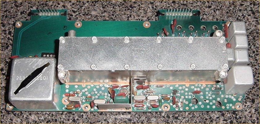
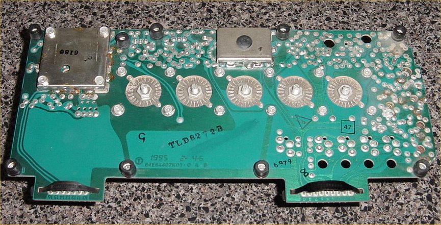
TLDXXX2 (142 - 150.8) [M] TLD8272 shown above.
TLDXXX3 (150.8 - 162) [H]
TLDXXX4 (162 - 174) [HH]
The XXX can be just about anything. Commonly the XXX will be:
407 (8 channel) [older]
527 (4 channel) [older]
577 (8 channel) [newer]
827 (4 channel) [newer]
845 (Extender) [noise blanker]
The 132 - 142, and 150.8 - 162 oscillator multiplier sections (capacitors)
are the same.
The 142 - 150.8 and 162 - 174 oscillator multiplier sections (capacitors)
are the same.
The 132 - 142 and 142 - 150.8 receivers use a 'low split' helical resonator
casting.
The 150.8 - 162 and 162 - 174 receivers use a 'high split' helical
resonator casting.
The low split helical resonators were made with a yellowish plastic
coil form, while the 150.8 - 174 resonators forms were white or clear.
There are four other minor differences between the RF - I-F boards:
R107, R122 and R123, and L112. We don't change resistors R122 or
R123 when we convert a HH to a M as it has been found they don't change
anything except the linearity of the DC characteristics of the discriminator
which I feel only affect the tracking of the optional AFC module.
R107's value follows the same rule a the front end casting; it is the same
in the L and M, and changed to another value in the H and HH. I
have no idea why this resistor is different because it lies in a section
of the receiver that only handles the I-F. Since the I-F never changes
no matter what happens in the oscillator/multiplier or front end, I have
no idea why it needs to be changed, so we don't change it when converting boards
either.
L112's value is only different in the HH split, being the same in the
L, M, and H, so it needs to be changed when converting an HH to an M.
The result of these component differences results in 4 different receiver
RF - I-F boards that follow the rule below:
TLDXXX1 (132 - 142) [L]
TLDXXX2 (142 - 150.8) [M]
TLDXXX3 (150.8 - 162) [H]
TLDXXX4 (162 - 174) [HH]
If you want to convert a 150.8 - 174 MHz. MICOR receiver to the 2 meter band, go here.
Copyright© 1998 Kevin K. Custer W3KKC e-mail Kevin with comments, suggestions, or notes.