Index Page
Compiled and HTML'd by Mike Morris WA6ILQ
Formerly Maintained by Robert Meister WA1MIK (SK)
Presently Maintained by Mike Morris WA6ILQ
| Back to Home |
The Index Page Compiled and HTML'd by Mike Morris WA6ILQ Formerly Maintained by Robert Meister WA1MIK (SK) Presently Maintained by Mike Morris WA6ILQ |
Zetron, Inc. manufactures integrated communications systems. The company was founded in 1980 and the product line is oriented towards the Land Mobile Radio marketplace, specifically Public Safety Agencies, Utilities and Emergency Transportation Companies – Zetron manufactures nothing specifically aimed at the amateur radio market. However, a number of amateur repeater and remote base systems have made use of Zetron equipment to resolve specific issues.
See this Zetron Introductory Information page for background, commentary, and some other useful information.
Like any major manufacturer there is a Zetron-specific mailing list at https://radios.groups.io/g/Zetron.
If you have a manual PDF that we do not have, a wiring hint, a firmware update, a programming trick, an undocumented master password, or any other useful information, please consider sending it to the page maintainer above.
If the 9-pin serial port on your Zetron unit seems to be non-responsive there is a simple fix - just scroll down to the Zetron Cables heading at the bottom of this page.
One of the things we are looking for is the schematic of the Zetron-designed Motorola CDN6351A cable (possibly CDN6321A) that was designed to connect external equipment to a paging or repeating station like the MTR2000, PURC5000 or MSF5000. It has an integrated summing amplifier that mixes multiple sources into one output. At one point it was priced at over US$300. if anyone has a schematic we'd appreciate it. If anyone has access to one one we'd like a few photos.
Manuals and Articles:
A number of the files below are not text searchable. If you have a later one or have access to an OCR system that can convert them please contact the page maintainer.
Default passwords - for those units that need them - can usually be found in the manuals.
|
|
HEAR (Hospital Emergency Adminsitrative Radio)
Decoder Brochure (005-1222B) 35 kB PDF file There is no model number on the data sheet, just the name "H.E.A.R. Decoder". This unit is a late 1960s - 1970s unit and is normally paired up with a tone remote unit like a Model 280 or Model 284 connected to a VHF base station. The two most common frequencies were: 155.340 MHz, primarily for vehicle to hospital communications, and 155.280 MHz for hospital to hospital communications. Locally here in Southern California the 155.34 is pretty much unused as it was replaced with the UHF "Med" channels. (off-site pointer, opens in a new browser tab and into the middle of a web page) |
|
|
Model 5 Encoder Instruction Manual (025-9099L.2) 2 MB PDF file Sequential 2-tone and 5-tone selective calling encoder |
|
|
Model 8B Repeater Programmer / Timekeeper Instruction Manual 1.9 MB PDF file Interfaces with Model 38 repeater tone panels. Decodes all tones and digital codes. |
|
|
Model 15 Operating Manual
(025-9003L) 6.6 MB PDF file Universal station encoder for selective calling. Does just about every paging format in use in the 1990s. |
|
|
Model 15P Field Programmable Multi-Format
Encoder Operator's Manual (025-9235E.1) 890 kB PDF file This is apparently a successor to the Model 15B Encoder. |
|
|
Model 18 and 18+ Control Link Installation and
Operations Manual (025-9214C) 4.3 MB PDF file The Model 18 handles digital I/O only; the Model 18+ handles analog I/O and twice the digital I/O of the model 18. |
|
|
Model 19B Simplexor Brochure
(005-0406C) 38 kB PDF file Model 19B Simplexor Instruction Manual (025-9179K) 1.6 MB PDF file Model 19B Simplexor Schematic 452 kB PDF file |
|
|
Model 21 Instant Recall Recorder Installation and Operation Manual (025-9074L) 9.3 MB PDF file |
|
|
Model 25 Programmable Encoder Operator's Manual
(025-9025A) 693 kB PDF file Model 25 Programmable Encoder Programming Guide (025-9057G) 2.6 MB PDF file Model 25 Programmable Encoder Technical Manual (025-9018R) 5.8 MB PDF file Model 25 Programmable Encoder Technical Manual 5.1 MB PDF file (text searchable) |
|
|
Model 27 Receiver Monitor Panel
(025-9186D) 2.46 MB PDF file (text searchable) Courtesy of Christopher Ryba KC3GDO |
|
|
Model 30 Worldpatch Brochure
(005-0339H) July 2001 Version 900 kB PDF file Model 30 Worldpatch Brochure (005-0039J) May 2011 Version 491 kB PDF file Model 30 Worldpatch Brochure (005-0039K) May 2018 Version 491 kB PDF file Model 30 Worldpatch Instruction Manual (025-9140P) 2000 Version 500 kB PDF file Model 30 Worldpatch Instruction Manual (025-9140R) 2013 Version 664 kB PDF file Model 30 Worldpatch with Selcall Instruction Manual (025-9431B) 2000 Version 1.1 MB PDF file |
|
|
Interfacing a Zetron Model 30
Worldpatch (Phone Patch) to a MotoTRBO Repeater 300 kB PDF file, author unknown, could be by Motorola? The Model 30 interfaces to a full duplex base station, uses +12v for power, connects to receive audio, COR and optional PL decode, transmit audio and PTT. Programming is via a DTMF decoder internal to the Model 30. This document appears to be oriented towards the XPR series of repeaters however much of the information is applicable to others. |
|
|
Improving the audio response of a Zetron Model 30 Worldpatch by Stig Kristiansen OZ3XO |
|
|
Model 32 DAPT-Jr Operating Manual (025-9040M) 12.4 MB PDF file |
|
|
Model 35A Brochure (025-9044S) 2.2 MB PDF file Model 35A Microconnect Operator's Manual (025-9044S) 1.05 MB PDF file Model 35A Microconnect Operator's Manual (025-9044T) 10 MB PDF file Model 35A Microconnect Operator's Manual (025-9044U) 950 kB PDF file |
|
|
Model 37 Repeaterman Instruction Manual (025-9180F.2) 1.5 MB PDF file |
|
|
Model 37-MAX Repeater Pal Installation Manual (025-9376A) 1.1 MB PDF file (no schematics) |
|
|
Model 38 Repeater Panel Sales Brochure
(005-0141J) 61 kB PDF file Anybody have any other docs on a model 38? |
|
|
Model 38A Instruction Manual
(025-9043Y) 1.34 MB PDF file Model 38A Repeater Panel Schematics-only 375 kB PDF file Model 38A Repeater Tone Panel Instruction Manual (025-9043Y) (with scanned schematics) 1.17 MB PDF file (text searchable) Donated by Eric Lemmon WB6FLY The cable that plugs into the 38A is part number 709-7112 (and the price in fall 2006 was US$35). This is the generic cable with flying leads (as opposed to one that has a connector that is designed to plug into some other manufacturer's specific equipment). BTW the differences between a 38 and a 38A are significant changes to both firmware and circuitry. They are similar in function and name but internally they are essentially two different products. |
|
|
Model 38-MAX Brochure (005-0605C) 51 kB PDF file Model 38-MAX Manual (025-9263B.1) (with schematics) 5.1 MB PDF file |
|
|
Model 39 Premium Repeater Panel Brochure (005-0289F) 61 kB PDF file |
|
|
Model 39-MAX Instruction Manual (025-9113G) 3.7 MB PDF file |
|
|
Model 40 System Patch Instruction
Manual (025-9136G) 1.13 MB PDF file Model 40 System Patch Repair Manual 520 kB PDF file courtesy of VA3KMC |
|
|
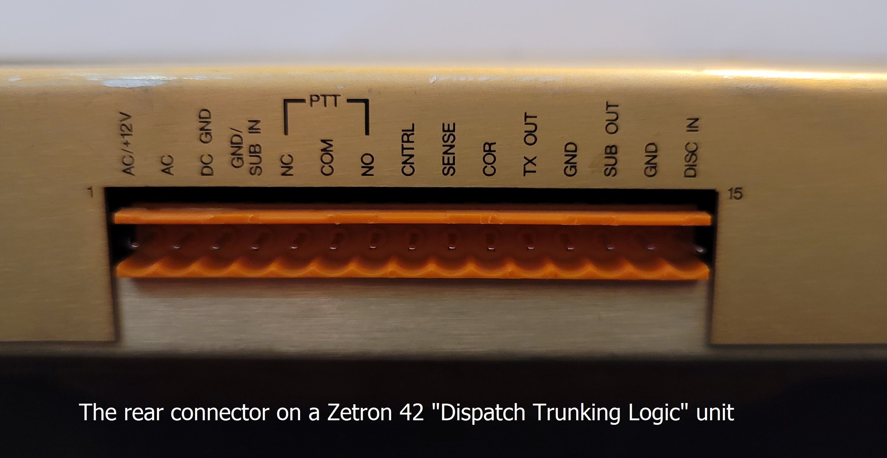
Model 42 Dispatch Trunking Logic Operation and Instruction
Manual (025-9251D) 11.24 MB PDF file Despite the somewhat misleading name this unit is a single channel LTR trunking controller in a 1 Unit rack mount housing. The model 49 is the same unit with the addition of a modem board (which requires a 2 Unit rack mount housing). Either will work with any radio that has a discriminator output and a transmitter that has a separate voice and digital (DPL or paging) inputs. Zetron offered a number of cables to connect the Model 42 or Model 49 to the different repeaters of the day, and they also offered a generic or universal cable, the part number #709-7116 revision B3. Your author has about 25 of the Model 42s in service at several sites on a variety of repeaters plus has seen them on everything from GM300 pairs, R1225s, Icom FR5000s (VHF) / 6000s (UHF), TKR-7xx / 8xxs to MTR2000s and more. Internally the unit uses a 68HC11 CPU and a single 27C256-120 EPROM for the firmware and does not need a coin cell for memory backup. The latest firmware he has seen is version 2.62. If anyone has anything later (even an image file) please contact him. You cannot mange or program the Model 42 or the Model 49 without the management software! An MS-DOS program called "MultiBase" is required is and was included on a floppy free in the box with the Model 42's and model 49's. The author has Multibase running in DOSbox-X (MS-DOS 6.22) on a Windows laptop located at every site and can remote into it over a VLAN to manage all of the Model 42s at a site. The Model 42 has a female DE-9 serial connector on the front panel for programming the unit - and it has a nonstandard pinout - see the information in the Zetron Cable section below. During a telephone conversation with Zetron Tech Support a comment was made that "Unfortunately everybody that knew anything about this equipment has retired or left the company...", so there is ZERO support except for a downloadable PDF manual scan, and the cable diagram, both of which we offer here. One of the Zetron Tech Support people told me that the manual had been created in CP/M WordStar(!) and that the PDF was made by scanning a printout! Unfortunately the manual is not text searchable because it is an image scan. |
|
|
The Zetron billing system for the Model 42 or the Model 49 was called ZEBRA - anybody have a copy? |
|
|
Model 45 Z-Patch Installation Manual
(025-9958G) 12.3 MB PDF file Even though its title says installation, this includes operation, programming, and service information. |
|
|
Model 45B Brochure (005-0046I) 2.5 MB PDF file Model 45B Z-Patch Installation Manual (025-9092Q.1) 8.8 MB PDF file; Contributed by Lee Simon KE7EYX |
|
|
Model 48Jr Brochure (005-1073E) 105 kB PDF file Model 48-Jr Repeater Patch Installation Manual (025-9362C) 562 kB PDF file (text searchable) (no schematics) Pieces scanned by Barry Palmore, compiled into one file by Richard Schiller W4RSE. Model 48-Jr Repeater Patch Installation Manual (025-9362C) 3.5 MB PDF file (with schematics) Courtesy of Gregory Ross AIØB |
|
|
Model 48B Repeater Manager Instruction
Manual (025-0090K) 12 MB PDF file Model 48B Repeater Manager Instruction Manual (025-0090K) 39 MB PDF file Two different people sent in the files, one was Eric VE2VXT. If you have the bandwidth / download time / disk storage space, get the bigger one. Anybody have any other info? |
|
|
Model 48PB Repeater Manager Installation
Manual (025-9090N) 12 MB PDF file Model 48PB Repeater Manager Technical Manual (025-9091B) 7.3 MB PDF file |
|
|
Model 48-MAX Brochure
(005-1023E) 123 kB PDF file Model 48-MAX Technical Manual (025-9344E) 6.68 MB PDF file |
|
|
Model 49 Trunking Repeater Manager Operation and
Installation Manual (early 025-9108R) 13.85 MB PDF file Model 49 Trunking Repeater Manager Operation and Installation Manual (late 025-9313D) 17.5 MB PDF file This is a Model 42 LTR controller in a double high box. It is essentially identical but with an added internal telephone interconnect / system management modem. See the comments above on the Model 42. Everybody that knew anything about this equipment has retired or left Zetron... zero support. |
|
|
Model 42 / 49 Multibase Operation Manual (early
025-9173G) 7.1 MB PDF file Model 42 / 49 Multibase Operation Manual (late 025-9297D) 32.8 MB PDF file |
|
|
Model 66 Transmitter Controller Operation and Maintenance Manual (025-9078W) 6 MB PDF file |
|
|
Model 72 Brochure (005-0423E) 612 kB PDF file Model 72 Instruction Manual (025-9189G) 3.5 MB PDF file |
|
|
Model 80 TrunkBridge Instruction Manual (025-9181E) 1.5 MB PDF file |
|
|
Model 250 Tone Remote Adapter Installation Manual (025-9472C) 456 kB PDF file (text searchable) |
|
|
Model 251 DC Remote Base Station Adapter data sheet (005-1371A) 555 kB PDF file |
|
|
Model ZR310 Community Repeater Panel Service Manual 640 kB PDF file (text searchable) Usually found in GR300, 400, 500, and CDR series low-end repeaters. |
|
|
Zetron manufactured a number of products for Motorola's low-end MaxTrac and GM300
based repeaters (Desktrak, GR300, GR400, GR500, GR1225), including the Zetron ZR320
Selective Calling Interconnect Controller (known as part number HLN8389), the Zetron ZR330
Remote Telephone Interface (HLN8390), and the Zetron ZR340 Advanced Interconnect Repeater
Controller (HLN9119). All of these are documented in the GR300 and GR500 Repeater Service
Manual, number 6880903Z42-A.
This manual is no longer available but a 9.3 MB PDF file can be downloaded from
the MaxTrac Index page at this web site. The relevant sections from that manual have been separated into several PDFs here: Model ZR320 Programming 1.52 MB PDF file Model ZR320 Selective Calling Interconnect Controller 855 kB PDF file Model ZR330 Programming 241 kB PDF file Model ZR330 Remote Telephone Interface 364 kB PDF file Model ZR340 Advanced Interconnect Repeater Controller 487 kB PDF file Model ZR340 Programming 609 kB PDF file |
|
|
Model 350 Europatch Brochure
(UK005-0077A) 107 kB PDF file Model ZR350 Europatch Instruction Manual (025-9375C) 556 kB PDF file Despite the name "Instruction Manual" this document has all available information, including service schematics and programming instructions. |
|
|
Model 452 and Model 459 Trunking Controllers Installation
and Operation Manual (025-9450A) 14.3 MB PDF file Model 452 and Model 459 TCBase Operation Manual (025-9451A) 24.9 MB PDF file |
|
|
Model 735 Brochure (UK005-0056B) 441 kB PDF file This unit is oriented toward European phone systems. |
|
|
Model 745 Brochure (005-1335B) 88 kB PDF file This unit is oriented toward European phone systems. |
|
|
Model 748 Repeater Manager / Teleconnect
Technical Manual (025-9368H) 1.5 MB PDF file The 748 is just an upgraded 745; this manual should be useful on both units. |
|
|
Model 2540 FASTNet Switch Installation and
Maintenance Manual (025-9260C) 5.5 MB PDF file Model 2540 FASTNet Switch Operation and Programming Manual (025-9270G) 6.1 MB PDF file |
|
|
Model 4010 Radio Dispatch Console
Installation and Programming Manual (025-9227S) 3.5 MB PDF file Model 4010 Split 50 66m Type Punch-Down Block Signal Identification Diagram 210 kB PDF file from the above manual. Model 4010 Radio Dispatch Console Programming Manual (025-9229C.1) 2 MB PDF file Model 4010 Radio Dispatch Console Service Manual (025-9228H) 8.2 MB PDF file This file is meant to be printed on 11x17 paper. Many sheets contain two pages of info. |
|
|
Model 7502 Mobile Dispatch Unit Instruction Manual (025-9249A) 2.1 MB PDF file scanned by Joe WA7JAW |
|
|
DeadBolt Lightning Surge Arrestor
Brochure (005-0557D) 39 kB PDF file This unit is a phone line protection device (overvoltage, lightning, RF, etc). Anybody have the Instruction Manual, Repair Manual or Schematic? |
|
|
Telephone Radio Headset Interface (TRHI) Manual (025-9553C) 1.6 MB PDF file |
Programs:
|
|
Fastbase V7.10 260 kB |
|
|
Multibase V6.18 250 kB |
|
|
Multibase V6.20 250 kB |
|
|
Multibase V6.21 250 kB |
|
|
TCbase V1.00 230 kB |
|
|
TCbase V1.0b 230 kB |
|
|
Zetron Hardware Configuration Program (ZHCP) V3.10 200 kB |
Zetron Cables: Are there any other Zetron cables that should be on this page?
In 1962 the Electronic Industries Association (EIA) introduced the RS-232 (the "RS" stands for "Recommended Standard") to simplify serial communication between data terminal equipment (such as a computer terminal) and data communication equipment (later redefined as "data circuit-terminating equipment"), typically a modem. The first version of the RS-232 standard specified 25 pins, but they unfortunately they didn't specify the connector! It took a few years but everybody eventually landed on the Canon DB-25.
When IBM introduced the PC in 1981 they used the female DB-25 as a printer connector and the male DB-25 as the serial connector using the EIA Standard RS-232 pinout. When they introduced the second generation (the "Advanced Technology" ("AT") series) around 1984-1985 they switched to the nine-pin Canon DE-9 connector for the serial ("COM" ports). A number of companies (including Zetron) had standardized on the nine-pin Canon DE-9 for serial communication and had been using a specific pinout for many years. Unfortunately IBM went their own way (just like they did on EBCDIC over ASCII in the 1960s) and chose to use their own RS-232 pinout on the 9-pin connector. The symptom of this situation is that your terminal program (such as TeraTerm on the PC) will display the startup message of the equipment, but it ignores your keyboard entries. If you run into this situation you will need to either buy an expensive cable from Zetron, or make up your own cable with this pinout:
| Zetron cable part number 709-7144 | |||
|---|---|---|---|
| Computer End (female DE-9 connector) |
Zetron End (male DE-9 connector) |
Notes | |
| Pin | Data Flow | Pin | |
| 1 | The official Zetron 709-7144 cable has no conenction to PC pin 1. | ||
| 2 | <------ Zetron Transmit Data / PC Receive Data |
3 | This is the same as the PC, so you will see the Zetron-equipment-generated power-up message. |
| 3 |
------> Zetron Receive Data / PC Transmit Data |
4 | This is the zinger! The rest of the world listens on pin 2, Zetron listens on pin 4! |
| 4 | Data Terminal Ready (PC output) | The official Zetron 709-7144 cable has PC pin 4 jumpered to pin 6. | |
| 5 | Ground | 5 | Fortunately this is the same. |
| 6 | Data Set Ready (PC input) | The official Zetron 709-7144 cable has PC pin 6 jumpered to pin 4. Some Zetron equipment has +12vDC on pin 6. This simulates an active DSR signal if this pin is connected to pin 6 on the computer end. |
|
| 7 | Request To Send (PC output) | The official Zetron 709-7144 cable has PC pin 7 jumpered to pin 8. | |
| 8 | Clear To Send (PC input) | The official Zetron 709-7144 cable has PC pin 8 jumpered to pin 7. Some Zetron equipment has audio on pin 8. Personally, I'd leave this pin unconnected. |
|
| 9 | 9 | Some Zetron equipment has a second ground pin here. The most common use of pin 9 on the computer end is the Ring Indicator signal from a modem to the PC. I'd leave pin 9 unconnected on both the PC end and the Zetron end of the cable. |
|
Summary: Take a 3-wire DE-9 crossover ("null modem") cable and move the pin 2 wire on the plug end (the Zetron equipment end) to pin 4. Label the modified cord "Zetron Only". Done!
Personally, I try to minimize the cable count in my field computer backpack. So when I started working on Zetron equipment I made up a custom cable that has two mini-toggle switches mounted in the connector shells:
a) A tiny DPDT switch in the computer end connector shell provides a pin 2 to pin 3 swap function (a 2-wire null modem).
This switch is labeled as "Null Modem" or as "Normal".
b) Plus a tiny SPDT toggle switch in the Zetron end connector shell... it switches the data going to the Zetron from pin 2 to pin 4.
This second switch is labeled as "Normal" or as "Zetron".
The end result is that I have one male-to-female cable that can function as a 3-wire serial extension cable, or as a 3-wire "null modem" cable or as a Zetron-specific console cable.
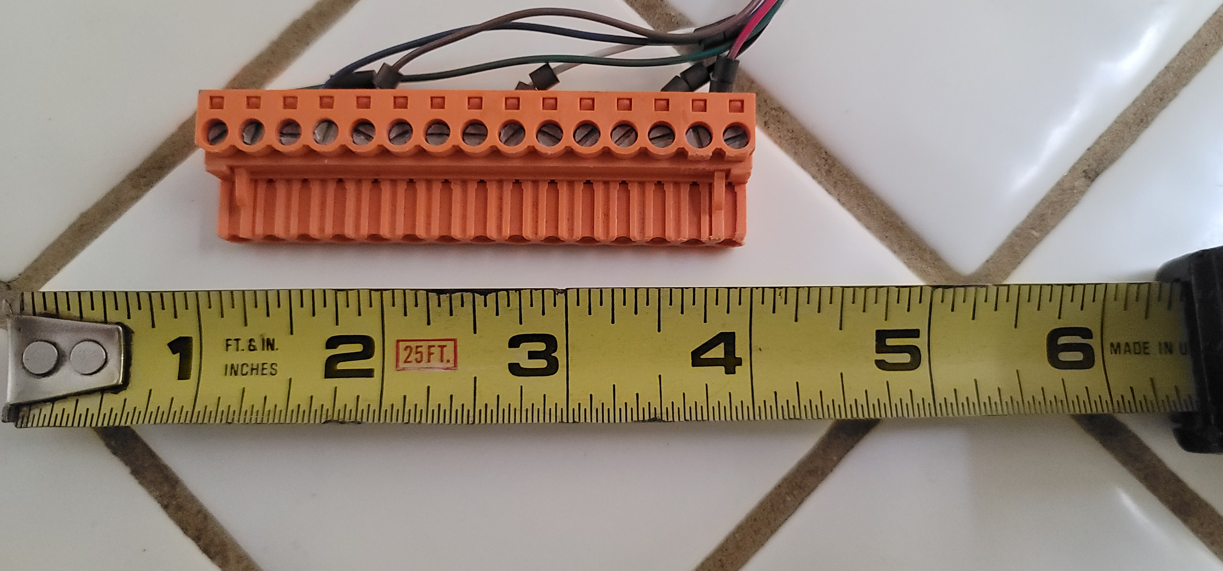
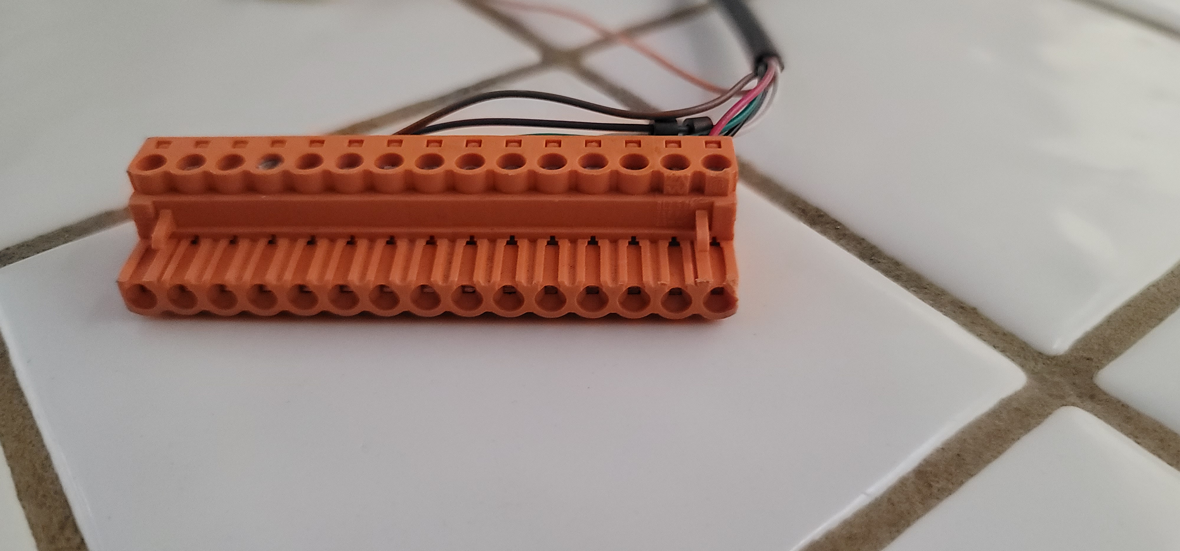
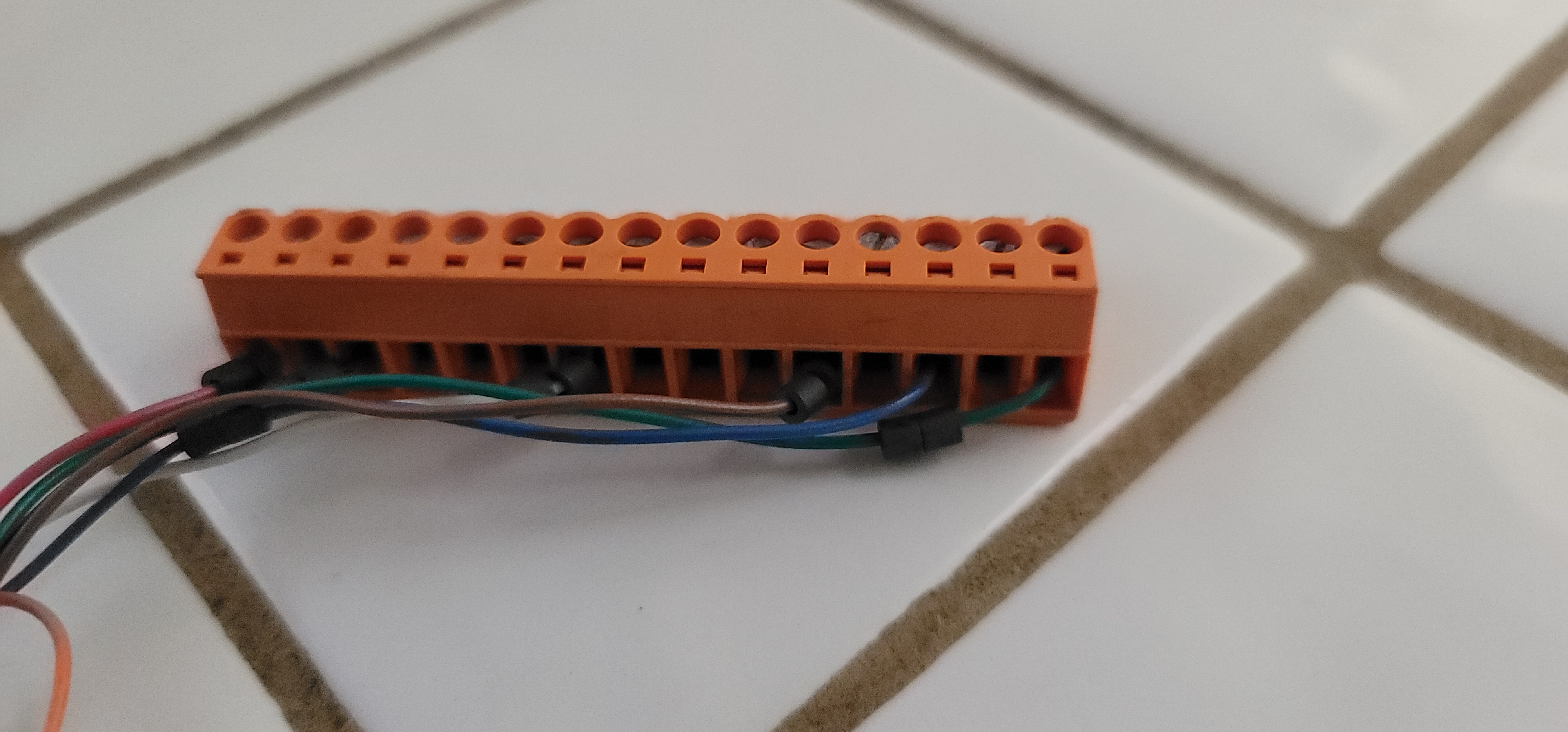
Zetron Connectors:
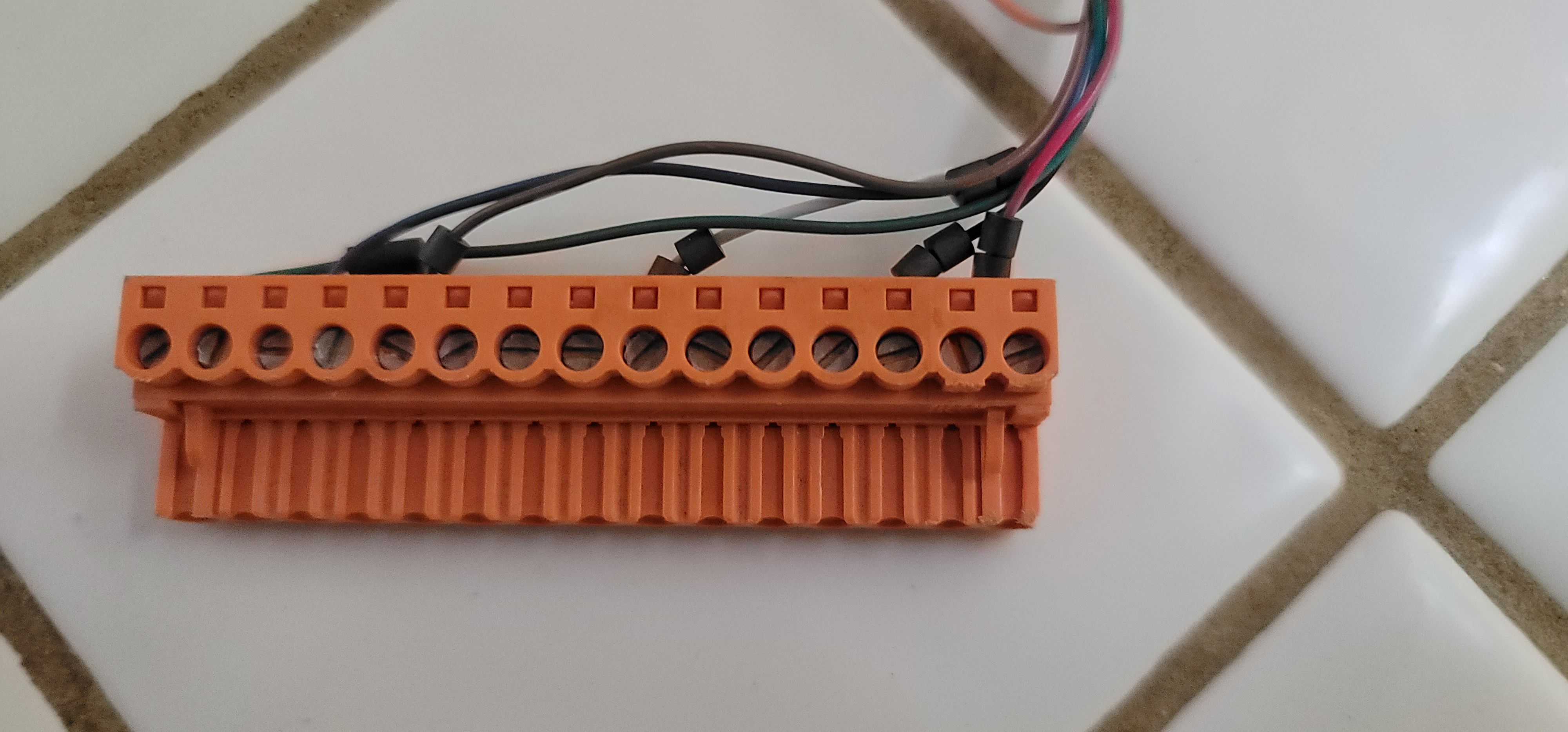
On many of their units Zetron uses a single-row 15 pin connector, originally made by Weidmuller.
Today the connector is available from Phoenix Contact, (http://www.phoenixcontact.com).
The 15 pin cable-end connector (the part that plugs into the connector on the back of my Zetron model 42s) is part number is
1757145. The data sheet shows it in green, I have also seen them in orange.
Mouser knows that connector as a 651-1757145, Digikey as a 277-5795-ND.
It is a 15 Position 5.08mm pitch unit for 24-12 gauge wire.
The price at Mouser in 2010 (as this paragraph is being added) was about $12.50 plus shipping.
Photo 1
Photo 2
Photo 3
Photo 4
Photo 5 (the mating connector)
And the ferrite beads don't come with it... (this is a factory Zetron cable for a LTR trunking controller.
Other Zetron units use a 10 pin, I haven't needed to research that part number.
Zetron DTMF Microphones:
The one manual we have is for the ZMX Microphone, 1.98 MB PDF, courtesy of
Kyle KØKN
Manual # 025-9363F.1
Zetron made several other DTMF microphones, including a ZML model.
If anybody has any photos we'd love to have image files.
If anyone has additional manuals we'd love to scan and return.
Access the program mode by turning off the radio, then:
1) Press and hold the 1, 2, and 3 keys.
2) Turn on the radio power.
3) Release the 1-2-3 keys. (you will hear a series of beeps indicting program mode)
4) Initialize to factory defaults by pressing 8 0 # ( more acknowledgment beeps)
5) Enter 5 2 # ( more beeps)
6) Exit the program mode by pressing 0 #.
7) This should put the microphone into the manual DTMF mode.
Known jumpers are : JP3 Flat audio out, JP4 Low Impedance, JP6 External power.
Legalities:
Zetron, Simplexor, Worldpatch, Microconnect, Repeaterman, Europatch, DeadBolt and probably a few other terms are either service marks, trademarks, or some other legal mark and no infringement is intended. If Zetron had these files or this information on their public web site we wouldn't need to.
Back to the top of the page
Back to Home
The Zetron index was initially created 14-Oct-2004 by Mike WA6ILQ and subsequently added to and maintained by Robert Meister WA1MIK (SK).
This web page, this web site, the information presented in and on its pages and in these modifications and conversions is © Copyrighted 1995 and (date of last update) by Kevin Custer W3KKC and multiple originating authors. All Rights Reserved, including that of paper and web publication elsewhere.