Photos below are thumbnails, click for full size.
The VHF Syntor X was made in two ranges, 136-154.4 MHz (rare) and 150-174 MHz (much more common).
Steps:
- Program the Syntor X EEPROM as a 136-154 MHz split radio. It's best to start with a "New" template and assign 144.39 MHz as the default frequency. Disable scan, set it to CSQ (carrier squelch) for both TX and RX, and set all other options to OFF. The time-out timer should be 1 minute (wish it would let us select 10 seconds like I use on my Maxtrac / Radius / GM300 radios!)
- Reinstall the EEPROM and open up the VCO cover (4 screws, and pry it up.)
With the radio front connector facing you, find C1436 (above and to the right of the screw, parallel to the front cover) and
C1435 (directly below the screw, also parallel to the front cover.)
UPDATE: Different boards have different numbers for the capacitors. They are always in the same places on the board.
Bridge C1436 with a 47pf capacitor (preferably a chip cap, but other small cap will work) and bridge C1435 with a 75pF capacitor.
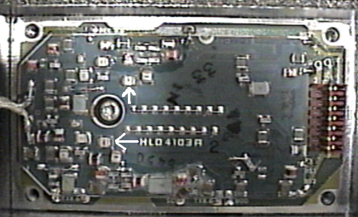
You should now have VCO lock, as indicated by a the "Unlock" LED on the other side of the board being dark during both TX and RX.
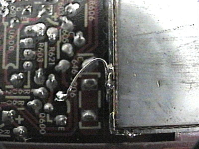
UPDATE: It also helps to jumper Q600's collector on the receiver board (range select) to ground.
Ideally the steering line voltages on TX and RX should be in the middle of the 1.3 to 9.0 volt range.
- Generate a weak signal on 144.39 - you should hear it at around 10 microvolts. Don't panic yet.
Find the helical adjusting screws (the ones that say "DO NOT ADJUST") and break the plastic coating off the ends.
Then tune each one for a peak in received signal. You should see about 0.2 microvolts for 20 db quieting when done.
 .
.
- Key the transmitter and inject audio or yell into the microphone. You'll see only 2.5 KC deviation.
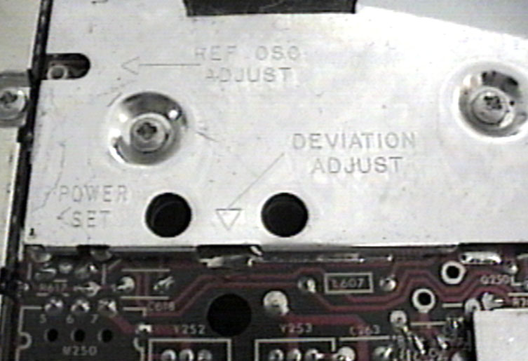
Again, don't panic. Readjust the deviation control (diagram above) for 4.75 KC.
Also set the power control for desired output.
Road map: The power set adjustment is the hole on the left. It is backwards (CCW = increase).
Deviation adjustment is the hole BELOW the shield at the bottom of the picture.
The hole on the right is deviation compensation - do NOT adjust unless you're using digital coded squelch (Motorola DPL)!
On the far left, Ref Osc Adjust is your master frequency trimmer.
On the "common circuits board" (other side of radio, this same board)... If you loosen the three screws and swing the board out you will find a pot closest to the heatsink end of the radio. This is "current limit adjust" and you may need to tweak it for maximum power.
- Connect the wires to the front connector as shown:
Syntor-X
Pin | Function | KPC-3
Pin |
| 4 | Push To Talk | 3 |
| 2 | RX audio | 5 |
| 15,5,A | + 12 volts | 7 |
| 10,8,B | Ground | 6 |
| 27 | TX audio | 1 |
There you go! You should have the loudest digi around, or the best backwoods tracker available!
Just remember that you'll be drawing about 30 amps if you run the radio wide open (around 150 watts) so use the correct size wire!
OPTIONAL:
The Syntor-X had several options that we are not covering in this article, which is oriented to a single channel radio.
If you wish to have multiple channels then you will have to connect the channel select pins. Do NOT drive them with a voltage!
They are grounded (switch contacts, open collector driver transistor) for inactive and floating (pulled high by the radio).
If you have a single zone radio (16 channels, however Moto also sold an 8 channel control head) your binary channel data
is from this 16 channel table.
Ground control head connector pins 12, 16, 23 and 29 to force the Syntor-X to go into binary channel select mode.
For 32 channels (a two zone radio) your channel data table is now this table.
Ground control head connector pins 16, 23 and 29 to force the Syntor-X to go into binary channel select mode.
(Note that pin 12 is now a frequency select line where in a single zone radio it was grounded).
Use the "Repeat/Talkaround" or "A/B switch" option when programming the EEPROM module.
Up one level (Syntor Index Page)
Up two levels (Motorola Index Page)
Back to Home