
|
Motorola index Back to Home |
The Motorola CDM Series Mobile Radio Index Page And with some information on the Waris handhelds (HT750 / 1250 / 1550 series) Originally created by Mike Morris WA6ILQ and improved upon by Robert Meister WA1MIK (SK) with information provided by several people. Currently Maintained and Updated by Mike Morris WA6ILQ |
DONATIONS OF INFORMATION, ESPECIALLY PDFs OF MANUALS WE DON'T HAVE WOULD BE GREATLY APPRECIATED.
Comments / critiques / suggestions / corrections / updates for this page are welcome and appreciated.
(Actually for any page at this web site)
Background Info
The CDM mobile radios are great radios… The "CDM" nickname was derived from the model number and is even mentioned in Motorola's original literature (see the sales introduction download below). They were introduced in 1999 and were the follow-on series to the MaxTrac / Radius / GM300 product line. There is a CDM model number decoder below. The CDMs were the mobile radios in the "Professional Series" product line which also included the HT750, the HT1250, and the HT1550 handhelds and used the same programming software (CPS). The code name used in the development of the Professional Series was "Waris" and you will find references to the Waris Series on other web pages. FYI, "waris" is the Hindi (India) word for "heir" (as in the heir to the throne)… (and there was a 1969 movie by that name that is interesting to see).
Think of the Motorola CDM mobile radios as an HT750 / HT1250 / HT1550 series handheld radio repackaged as a mobile except with a good (varactor tuned) front end on the receiver, a good power amplifier on the transmitter and a big display. My only gripe with the handhelds was that they did not use an SMA antenna. The CDMs are built in a very well shielded aluminum chassis. The interior of the radio is compartmentalized and each section of the radio is fully shielded from the others by the lid which has matching internal dividers for each section.
If anyone has additional hints / tricks / gotcha's, manuals or documents on any CDM mobile, an HT750 / HT1250 / HT1550 series handheld or any other Waris radio we'd be happy to post them… You can be credited or anonymous, your choice - please contact the page maintainer listed above.
For example, a step-by-step article on how to recover from the "EEPRM CS ERROR" situation would be useful.
Yet another example would be a step-by-step procedure to stretch the lower limit of the 450-512 MHz "S" range radios down to 440 MHz. without losing receiver sensitivity or transmitter power.
Unfortunately all CDM support has been discontinued as of June 2015. Parts are limited, some are No Longer Available ("NLA"), like the custom made-for-the-CDM (by Murata) surface mount wide band IF filters (but there is an alternative). Somewhere around 2001-2003 the CDMs were replaced in the sales book by the XPR series and the CM200, CM300 and PR400 series of mobile radios (which have their own page at this web site). Anybody know the actual XPR or CM introduction date?
The CDM series was also exported. In Europe the CDM750 is essentially a GM340, the CDM 1250 has no direct equivalent, the CDM1550 is a GM360. The firmware used in the GM340 and GM360 is different from the USA cousins. In other areas the CDM750 became the PRO3100, the CDM1250 became the PRO5100, the CDM1550 became the PRO7100. The GM338 is an Australian / Asian market version of the GM360. Despite the numbering, the GM350 was a generation before the GM340, it came in 4 channel and 128 channel versions.
There is also a GM950 4 channel and 128 channel which was essentially the same hardware plus a 5-tone signalling option.
Any other details on USA versus non-USA models would be welcome.
Anybody have any Service / Repair Notes or Field Service Bulletins to share?
Programming the "Professional Series" / "Waris" Radios: (the CDM mobiles and the HT750 / 1250 / 1550 series handhelds)
This CPS also programs these: MTX, EX500, EX600, EX600XLS, PRO5150, PRO7150, PRO9150, GP320, GP340, GP360, GP380, GP318, GP338, GP640, GP680, GP1280 and several others.
|
|
The Waris family radios are programmed by HVN9025 Professional Radio CPS which (according to Motorola) runs under Windows 95, 98, XP, 7 and 8 and can access COM1 through COM16. The author has run it on 32 bit Windows 7 and both 32 bit and 64 bit 10 without issues. Unfortunately you cannot clone one model of handheld to another or to a mobile or a mobile to a handheld. You CAN get around a password in a radio, we have an article on that (and two alternate procedures) below. The Waris radios were sold configured for conventional-only or conventional and LTR trunking , the only difference in the radios was firmware. Different firmware was used in the export models. The HVN9025 CPS was used for all. You want to find and use Revision R06.12.05 (released in December 2011) as it was last the last one that allows wideband or narrowband selection without a "Professional Series" wideband entitlement key (more on that below). Revision 6.12.05 can be found "out there". Coincidentally 6.12.05 was first one to run on both x86 (32-bit) and x64 Windows and runs on Windows 95, 98, XP, 7 and 10 (both x86 (32 bit) and x64 (64 Bit) versions). All CPS Revisions after 6.12.05 locks you to the 12.5 KHz (narrowband) unless you have a "Professional Series" wideband entitlement key – and the keys are different between MotoTurbo (DMR), Professional Series, and Commercial Series (and as of late 2024 those keys are No Longer Available - NLA). An email to Repeater-Builder reported that this "feature" bit the sender in the behind when he purchased a radio on eBay that was last programmed with a newer revision. He ended up reselling that radio on eBay and bought another as he needed wideband and couldn't get a key. The replacement CDM was happy with Release 6.12.05. I have been told that the only difference between Release 6.12.05 and the later revisions is the forced narrowband, the addition of a few newer model numbers into both the internal programming tables and into the directory that contains the sample codeplug files (and those sample files can be copied from the newer versions into your copy of Release 6.12.05). Unless you really need something in a later release (and you'd better have an entitlement key) there is no need to go anything newer than Release 6.12.05. And when buying a used Waris radio always ask the seller what revision the radio was last programmed with. In short:
|
|||||||||||||||||||||||||||||||||||||||||||||||||||||||||||||||||||||||||||||
|
|
If you don't read the 6.12.05 Release Notes all the way through you can overlook
a step in the installation on 64 Bit Windows. This is the reason for the
confusion where Revision 6.12.05 works for some people and not for others. If you get the error message "Can not create unknown radio component" when you start Revision 6.12.05 under 64 Bit Windows then you probably skipped an installation step or your copy of the CPS is missing an Executable file. To fix the error:
|
|||||||||||||||||||||||||||||||||||||||||||||||||||||||||||||||||||||||||||||
|
|
The Mobile Programming Cable: Motorola's literature lies and says that to program a CDM you need their AARKN4081A / RKN4081A RJ-45 (8 pin) CDM / CM200 / CM300 / PR400 series RIBless programming cable which has a 25 pin female connector (there's a circuit board inside) on the computer end, needs (and comes with) a 25 pin to 9 pin adapter and sells for about $250-$300. Here's the PDF that comes with the RKN4081. Photo 1 Photo 2 Photo 3 Motorola's literature lies. You don't need to spend $250-$300 to buy Motorola's special CDM programming cable, your existing RJ-45-style Maxtrac / Radius LRA / GM300 / R1225 cable (either 9-pin D connector or USB-based) will work just fine for everything except loading new firmware. If you don't already have an RJ-45 cable then get either this RKN4081 9-pin D connector to RJ-45 cable or this FTDI USB to RJ-45 cable (both links are off-site pointers and open in a new browser tab). If you are going to buy a USB cable then buy an FTDI based cable as they don't need any funny drivers, they work with the stock Windows drivers. I have seen reports on other mailing lists that people have had issues with Prolific-based cables. See the In Closing paragraph below. If you are part of the 5% that will need to update the firmware in a CDM then you will have to build or buy a RLN4853 Adapter Cable (which is easy, it is just two connectors and a few inches of 4-conductor cable). There is more info on it below. The Portable Programming Cable: RKN4075 cable (off-site pointer, opens in a new browser tab) is used to program the HT750, HT1250, HT1550, MTX150, MTX1500, MTX1550, MTX450, MTX4500, MTX4550, MTX850, MTX8250, MTX9250 and several other Waris handhelds. And the protective cover for the programming jack on the handhelds is a "HLN9820A Port Dust Cover" (replaces the 1586059A01). Replacement knobs for the HT750, HT1250, HT1550 (and maybe others) can be found at https://www.amazon.com/gp/product/B0GHFGY5G3. (off-site pointer, opens in a new browser tab) |
|||||||||||||||||||||||||||||||||||||||||||||||||||||||||||||||||||||||||||||
|
|
Recommendation: Save the original codeplug that came with your Waris radio and also save your tuning data (you will need the Tuner program to do that). You never know when you might need them. A firmware upgrade to a Waris radio will not change the tuning information. If your radio has a password it will prevent you from downloading the codeplug. You CAN get around it, we have an article on that below. I repeat: Before you do anything to a new-to-you Waris radio you need to read and save the original codeplug it came with AND use the Tuner program to read and save the tuning data. Having this data will allow you to fall back to a known starting point if you ever have a problem. It's best to have it and not need it than to need it and not have it and will never be able to get it. |
|||||||||||||||||||||||||||||||||||||||||||||||||||||||||||||||||||||||||||||
|
|
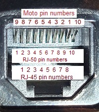
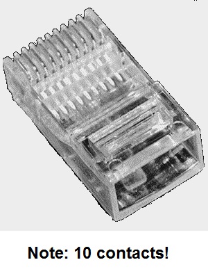
The front panel microphone connector (photo) on a CDM is a
10 pin, sometimes called a 10P10C modular plug. This is not the normal 8 pin (but your regular 8-pin programming cable and your regular 8-pin microphones will work just fine). The 10 pin connector plug body (photo) is the same size / width as the standard 8 pin and at first glance you won't realize that the CDM has a 10 pin microphone connector. Looking at the microphone jack with the tab down, Motorola numbered it left to right as 9-8-7-6-5-4-3-2-1-10, with 10 nearest the center of the control panel. The center 8 pins of the
10 pin connector are the same as the other radios that use an RJ45 microphone jack. The designers simply
added a pin on each side of the original 8 and numbered the new pins as pin 9 as EXT_KP_ROW and
pin 10 as EXT_KP_COL. The additional two pins are only used by the CDM-specific DTMF microphone to send the DTMF keyboard row and column info (as stepped DC voltages) to the microprocessor (which actually generates the DTMF tones). The standard CDM microphone is the AARMN4025 (but the Maxtrac, GM300 and other 8-pin microphones will work just fine), the 12 button DTMF microphone is part number AARMN4026B (there is no 16 button CDM DTMF microphone). Other manufacturers
that I have seen using the 10 pin RJ connector are some bar code scanners and the APC brand
UPS units (their proprietary 10 pin cable connects their UPS units to the USB jack on the host computer). Some literature (including tool catalogs) call the 10 pin RJ connector an RJ-50, others call it a RJ-48and one called it a "10 pin RJ-45". I've seen the 10-pin connectors and the matching
crimping tools listed as RJ-50 on eBay and elsewhere. In table form:
|
|||||||||||||||||||||||||||||||||||||||||||||||||||||||||||||||||||||||||||||
|
|
When programming a CDM mobile or a HT750 / HT1250HT750 / HT1550 (Waris series) handheld do NOT touch anything until you get the second set of beeps after loading a codeplug. The radio will beep when the codeplug load is complete, then the radio will reset and restart itself. That restart concludes with another beep. WAIT for that post-restart beep! If you start unplugging cables or shut off the power in-between the beeps you stand a good chance of corrupting the radio… This is the voice of experience. Yes, you can recover a corrupted Waris family radio, even one that doesn't boot. One of the features that was specifically included in the Waris family design was that it is almost impossible to completely brick a Waris radio. The Waris pages at the W9CR web site walks you through the recovery process. (off-site pointer, opens in a new browser tab) One caution: Do not let the power fail while programming the radio, ESPECIALLY while flashing / loading firmware. The author programs radios with a laptop that has a good battery plus is plugged into an AC outlet. He runs the radio from a common 12 volt 7 amp-hour battery during programming and flashing. This way another power outage at the wrong moment won't cause a problem. Second caution: If your CDM has a remote head or dual head environment Moto recommends that you disconnect any dual head kits or remote kits while programming. They say to use a local head only while programming and ESPECIALLY while loading firmware. |
|||||||||||||||||||||||||||||||||||||||||||||||||||||||||||||||||||||||||||||
|
|
You can program the CDM and even load firmware through the rear accessory jack if you use a
RLN4853 adapter. (link opens in a new browser
tab) You can build one yourself – it's very easy, look at the photo, it's nothing more than
a RJ45 female connector, a short length of 4-conductor cable (I used an old USB cable with the ends
cut off), and a 20-pin accessory connector… The schematic is on page two of the PDF. The author knows of a large amateur radio group that run a large number of CDMs without any heads – they are used as receivers, exciters, channel-steered remote bases, full duplex 420-438 MHz links (a pair on each end) and as control receivers. While they could be programmed by connecting a control head every single one has been (and is) programmed through the accessory connector. Kurt Meltzer, KC4NX / WB9KNX / Meltzer Radio Engineering sells a wide variety of connector / interfacing / cable kits on ebay as seller seller "mre1032", Kurt Meltzer, KC4NX / WB9KNX / Meltzer Radio Engineering. (off-site pointer, opens in a new browser tab) The last time I looked at his available list there were over two dozen listings for 16 pin cables for a number of Motorola models that use the 16 pin connector, and that wasn't including the 20 pin connector listings. His Cable Kit #93K" (off-site pointer, opens in a new browser tab) is perfect for building a CDM accessory connector programming adapter. His kit consists of a 20‑pin Motorola CDM acccessory plug and about 3 feet of 5 conductor (4 conductors plus shield) cable with the connector pins preattached... all you have to do is to slide them into the correct positions in the connector body. Add an 8‑pin female RJ-45 connector to the other end of the wires and you are done. Just plug your regular mobile programming cable into the adapter's RJ-45 jack and plug the 20-pin plug into the back of the CDM. Full Disclosure: I have no relationship with Kurt other than as a very satisfied email-order customer and he's not paying me for this recommendation. I just have 70+ year old eyes and have big fat fingers that have difficulty crimping the accessory connector tiny pins onto the individual wires, and then getting the pins into the plastic body rightside up (a large illuminated magnifying glass and needlenose pliers are a big help). I think Kurt's radio cable kits are wonderful. |
|||||||||||||||||||||||||||||||||||||||||||||||||||||||||||||||||||||||||||||
In Closing: If you do a lot of radio programming, especially away from the workbench, you might want to consider dedicating a computer to just radio programming. Over 10 years ago I realized that a laptop dedicated to radio programming would be useful. So I went looking and ended up with a Panasonic Toughbook that ran Windows XP and could be booted into MS-DOS with a floppy disk (a CF‑28). When it died I switched to a CF‑29 and gave away the CF-28. When the CF-29 hard drive died I gave it away and bought a CF‑30 (32-bit Windows 7) because it used common memory modules and a SATA hard drive. When the first Windows-10-only radio came along (a Motorola APX) I added a CF‑31 (64-bit Windows 10) to the collection.
I feel that the Toughbook CF‑30 and CF‑31 are the perfect ham radio field computer or radio programming laptop computers because they are cheap, readily available, configurable, easily repairable, Mil-Spec rugged and both have a 9-pin hardware COM 1 port on the back that avoids all of the USB driver issues and always works.
I use 9-pin serial programming cables when I can and when I do have to use a USB cable
I use nothing but FTDI-based cables because the FTDI cables run just fine with the stock
Windows drivers. I have not needed to install any proprietary USB drivers. A while back I
fought a battle with conflicting USB drivers and ended up wiping the computer and starting
over. I get my radio programming cables from Mark
Dunkle KJ6ZWL at BlueMax49ers. (off-site pointer, opens in a new browser tab)
His FTDI cables cost a little more but just plain work. And, no, he's NOT paying me for
providing this pointer, I doubt that he even knows that this web page exists.
There are more details here:
Some
Thoughts on Radio Programming Computers and Laptops. (opens in
a new browser tab)
Note: That article is an opinion piece and I guarantee that my needs were / are
different that yours… what works for me may or may not work for you…
(but that article may give you some ideas).
Tools:
You need a T20 Torx screwdriver and a small flat blade screwdriver to work on these radios. Some have T6 and T8 screws inside. The newer units have the six cover screws numbered #1 to #6 with numbers cast into the cover. Units that do NOT have the numbers are the older model with bipolar RF power amplifer devices with their own screws. Models with numbered screws have LDMOS devices in the PA and the circuit board does not have ANY screws holding it to the case - the board is held in place by pressure from the top cover pushing on the devices so they will couple properly to the thermal pads. Disassemble them by loosening them in the sequence #6 to #1 and assemble them #1 to #6.
Interfacing a CDM to External Equipment (the Accessory Connector): (repeater controllers, APRS encoders, etc.)
The rear acccessory connector on a CDM is identified on the schematics as J0501. The interfacing of a CDM is very similar to a R1225, GM300 or the previous Maxtrac and Radius LRA radios and you might want to look at those pages at this web site.
The CDR500 is the tabletop repeater housing that replaced the tabletop GR300 repeater in the Motorola product line. Likewise the CDR700 is the CDR500 in the GR500 wall-mount housing. Click here for the CDR500 / 700 brochure. Both the desktop and wall mount cabinets were shipped with same contents: a power supply, a pair of CDM750s, and optional duplexer and an optional control module. The most common option module was the HLN3333 Repeater Interface Communications Kit (R.I.C.K. or RICK) module – a very, very basic repeater controller however there are several others. While the standard factory configuration was a pair of CDM750s the CDR housings have been seen with a variety of CDM family radios, and I found one with a GM300 receiver and a CDM transmitter.
The CDR500 Wall Mount Repeater & CDR700 Desktop Repeater Service / Programming Manual (listed below) has almost nothing on the internals of the CDM radios (that information is in the Basic and Detailed Service Manuals) but it does have a lot of info on the interfacing to the CDMs, plus info on the various add-in controllers: the RICK, the ZR310, i20R, ZR340, HPN9005, HKPN4000, HKPN4001 and the HKN9033.
One major difference between the CDM series and the previous GM300 models: The GM300 has five
channel steering lines allowing binary selection through the accessory connector of 31 channels (plus
the one currently selected by (and displayed on) the control head) where the CDM has only four lines
(15 channels plus the one selected by the head). If you need five lines (31 channels+head)
then you'll have to skip the CDM and either go back to the GM300 series or use the later XPR series
radios.
More on this below.
|
|
The accessory connector on the rear of the CDM is made by TE-AMP and uses a 20 pin
connector body, not 16 like the previous
Maxtrac / Radius LRA / GM300 / R1225 models. The
center 16 pins are almost identical, the designer added two pins to the left of the old
connector, and two more pins on the right. Your
Maxtrac / Radius LRA / GM300 / R1225 cable will plug
onto the center 16 pins and work just fine – with one exception:
pin 15 used to be a speaker connection, it is now a DC analog voltage output and the pin 15 to
pin 16 speaker jumper in your old cable must be cut. More details below.
As I said above a wide variety of 16- and 20-pin connector cables and connector / interfacing kits / cable kits can be purchased from ebay seller "mre1032", Kurt Meltzer, KC4NX / WB9KNX / Meltzer Radio Engineering. (off-site pointer, opens in a new browser tab)
Accessory Connector Notes:
| |||||||||||||||||||||||||||||||||||||||||||||||||||||||||||||||||||||||||||||||||||||||||||||||||||||||||||||||||||||||||||||||
|
|
In some installations it would be useful to have a microphone connected to the accessory connector
of a CDM. Yes, it can be done... just make a cable using an 8 pin RJ45 jack on one end and
the other end is the 16-pin or 20-pin accessory plug. Connect it as follows (note that the ethernet
numbering is backwards from Motorola numbering):
Radio Configuration -> Accessory Pins tab -> Accessory Package: Default (which makes accessory connector pin 3 an External Mic PTT Input, Active Level = Low, and Debounce Enable checked). Radio Configuration -> Accessory Pins tab -> Set pin 6 as Mic Off Hook (Input), Active Level = Low, and Debounce Enable checked. Then Radio Configuration -> Accessory Configuration tab -> set External PTT Audio Source: Ext Mic Audio Done! |
|||||||||||||||||||||||||||||||||||||||||||||||||||||||||||||||||||||||||||||||||||||||||||||||||||||||||||||||||||||||||||||||
Channel Steering:
The CDM mobile supports binary "Channel Select" in the CDM RSS / CPS and it
functions like the GM300s "Channel Steering". However the CDMs have only four
channel select lines on the accessory connector where the earlier GM300 had five (the XPR series
also has five). To use this feature just program several of the general-purpose I/O pins for active-low
input and "Channel Select".
Channels 1, 2, 4, and 8 may be selected by grounding Channel Select line 1, 2, 3 or 4 respectively.
All other channels are selected by grounding multiple select lines in a binary (not BCD) fashion. If
you select a channel that does not exist (i.e. 10 channels are programmed and you select
channel 12), the radio the radio will buzz at you until you clear the selection. If you change
selections while the radio is keyed, it will stop transmitting and buzz at you until the PTT is released.
If you release all of these Channel Select lines, the pins float high (i.e. "channel zero")
and the radio reverts to the channel selected by the front panel (if present).
It is advisable to force select the channels and NOT use the no-channel-selected-equals-front-panel
selection as an operational channel. The front panel selection may not survive a power-off-and-back-on
reboot. The number of pins you program for channel select determines how many remotely
selectable channels you can access... two pins lets you select 3 channels, three pins gives you
7 channels, four pins gives you 15. On an XPR or a GM300 five pins give you 31.
Mounting and Brackets:
|
|
The mounting bracket bolts onto the CDM with either M5 or 10-32 threads (both will work). Motorola provided thumb screws with their kits. If you provide your own screws you should trim them to about 1/4 inch (6 to 6.5mm) length into the radio body – any longer risks damage to the electronics inside the radio. |
|
|
The GLN7324A is the standard mobile bracket. It will not fits low band CDM as the low-band CDMs are high power only and use a larger body and hence use a larger bracket, the RLN4774A. |
|
|
The RLN4781A is a bracket that mounts a VHF / UHF CDM into a standard auto radio DIN opening. It's widely used in the UK and Europe for mounting the radio into a taxi or shuttle bus dashboard. |
|
|
The factory tabletop tray for the CDMs is a GLN7326A. It has a front-facing speaker in the bottom, the GLN7318 is the same plastic tray but without the speaker (but you can add your own). If you want to disable the internal CDM speaker you need to upen up the head and disconnect it (there is no programming option or jumper). |
|
|
Novexcomm) (off-site pointer, opens in
a new browser tab) makes and sells a dual or single CDM rack mount chassis that is available with or without
your choice of a 15 amp 120vAC supply (for low power radios) or a 30 amp 120 / 240v
power supply (for high power radios or 240v mains) or no power supply at all (they also do custom work).
Look at their eBay store or if you want to save the eBay markup just order direct from their web page. They
aren't limited to CDMs, they make their rack mounts with your choice of any brand or model of radio and
can customize it. Disclosure: your page author has known the owner of Novexcomm (WB6SLC) for 40+ years. No, he's not paying for this pointer. |
DC Power and Power Supplies:
|
|
You don't need a lot of power supply to run a CDM as a control receiver, repeater receiver or link receiver…
On receive they draw less than 1/2 amp with the squelch open. Your author knows of a receive-only CDM radio
running in the back room at an ambulance company feeding a 24x7 audio logging recorder and running on a
12 volt 3/4 amp wall wart. The low power (25 watt) VHF and UHF radios draw about 8 amps on transmit, the high power (45 watt) ones pull about 14 amps, the 60 watt low band radios can draw as much as 18 amps. |
|
|
Motorola offers multiple DC power cords for the CDM:
|
|
|
Astron sells the SL-15SCDM 15 amp desktop radio housing / power supply for the low power CDMs. |
|
|
Samlex offers two different housing / power supply units for the CDM750, CDM1250 and CDM1550 series: the SEC-1212-CDM (12 amp for the low power CDMs) and the SEC-1223-CDM (23 amp for the high power CDMs). |
The CDM Control Heads and Remote Mount Kits:
There are three different control heads for the USA CDM product line. The CDM750 control head is a part number GCN6112, the CDM1250 head is a GCN6113 and the CDM1550 head is a GCN6114. There is a GCN6116 "Databox" Data Control Head for the radio modem version. There is also a "head" (I don't have the part number yet) that mounts on the front of the radio body when using a remote head. It has a 10-pin (RJ-50) (RJ-45-like) connector for the remote cable. You can program the P1, P2, P3 and P4 keys with numerous options but the up / down / left / right arrow keys are not programmable.
There is a connecting piece that fits between the CDM radio body and the control head. Motorola calls it a "backhousing", some people call it a head spacer, a spacer, an adapter ring, or a sleeve. The CDM750 control head looks very much like the CDM1250 and CDM1550 heads but it is a different physical size and has a different shape. As such there are two different backhousings: The CDM750 backhousing is part number 1586092B01 and the backhousing for a CDM1250 or CDM1550 is part number 1586093B02.
It is a good idea to consider the CDM head and backhousing as a paired set. This is the voice of experience.
CDMs can be remote mounted with the appropriate remote mount kit.
There are two different kits and the only difference betwen the kits is different
backhousing, sleeves or spacers, as mentioned above. The bracket for the
remote head is a 0764275B01 (which is not the same as the regular radio
bracket). The RLN4801 kit is for the CDM750 and the RLN4802 is for
the CDM1250 and CDM1550 radios. Neither kit includes the 10-conductor
interconnecting cable, you need to order a Cable Kit: RKN4077
(3 meters long), RKN4078 (5 meters long) or a RKN4079
(7 meters long).
Update March 2026: A friend pointed out that Amazon(!) has the 10-pin
RKN4077 3-meter cable for under US$20. (off-site pointer, opens in a new browser tab)
Moto's own literature says that there have been issues with programming CDMs with the remote mount kits connected. There is also a dual head kit for stuations like a single mobile radio shared by an ambulance driver and by the paramedic in the rear patient care area of the ambulance. Motorola says to never program the CDM with the dual head kit connected. Personally, I always program them either by a programming cable plugged into the microphone jack of the local head or by a programming cable that is pluged into the accessory connector. In other words disconnect the dual head interface box, attach a local head to the radio, then program it. Or disconnect the dual head interface box and program it through the accessory connector.
Control Head Internals:
Each of the control heads has it's own 68HC11 microprocessor inside, slaved to
the 68HC11 processor that runs the radio. If you have a flaky head just remember
that all of the silicone buttons on the front of the radio are electrically arranged in an
X-Y matrix that can be electrically very different than the physical arrangement.
Think of each button as having a virtual "row" and "column",
that can be very different than the physical row and column. Each button when
pressed generates two analog voltages based on "row" and "column".
Both the row and column voltages are fed to separate analog inputs on the control head
microprocessor.
If you have control head issues first swap the head if the issue follows the head
then unplug and plug each end of the ribbon cable. On a regular front-mount radio (not
a remote mount) the 12-conductor ribbon cable that connects the head to the radio is
part number 8486127B01. The same ribbon cable is used in the CDM750, 1250 and 1550.
There is a blue dot on cable to make sure it's not installed upside down.
The dot goes towards the "0" marking cast into the front of the radio.
Make sure that the ribbon cable is in the connector, it's easy to slide it into the slot
between the connector and the circuit board. Then carefully take the control head
apart… Moto wants you to use the 6686119B01 "Dismantling Tool",
however all that is needed is a plastic putty knife. Hint: Start on the bottom of the head
where a nick in the plastic won't show. The volume knob is snapped into the housing of
the head, the pot shaft just fits loosely into it. When you take the board out the
knob will stay in the front of the housing.
The exploded view in the Basic Service Manual is wrong! Make sure the PCB
contact pads under each button are clean. You can get pure alcohol to clean the circuit
board pads here. (off-site pointer, opens in a new browser tab)
When you put the head back together you have to make sure the D-shaped hole in the
volume knob and the D-shaped shaft are lined up.
Was the flaky head in a marine environment? Or in a beach patrol Jeep? It could have
salt deposits or corrosion inside the head. The CDM was never intended for the marine
environment – marine radios have better seals around any case openings.
Was the flaky head given a coffee or Coke bath? I've seen CDMs mounted vertically, on
the dash of a truck and in a school bus. All horizontal surfaces (like control head faceplates
on vertically mounted mobile radios) are magnets for soda cans and coffee cups. Someone
could have accidentally have spilled a soda or coffee that leaked into the volume control
hole or around the buttons on the head or into the speaker grille of the head before you got it.
The CDM (and others) Mini-UHF Antenna Connector:
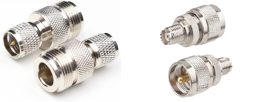
The antenna connector in the CDM series and many other Motorola radios is a Mini‑UHF female . The mini-UHF connectors were introduced in the 1970s, and first showed up in the consumer world in the old cellular mobile phones and similar applications where size is an important consideration. The mini-UHF uses a 3/8-24 thread size and Amphemol says it operates up to 2.5 GHz.
The mini-uhf connector is fragile comared to the standard UHF and the type N connector. This is especially true if you use stiff antenna cable like LMR400, RG213 or RG214 and a plug adapter adapter to the radio. Motorola offered a test bench adapter (mini‑UHF male to BNC female) back in the Maxtrac days and still does as the HLN8027 Mini‑UHF male to BNC female adapter (about $11). Your author considers a pigtail (mini‑UHF male to N female) cable with silver plated connectors and quality RG-400 cable to be a requirement for all mini-UHF connectors at radio sites. The pigtail relieves the stress on the radio connector. The broken connector problem got so bad that Motorola came up with two adapter cables: the 8 inch long HKN9557A Mini‑UHF male to UHF SO‑239 female Antenna Adapter Cable for about $19, and an 8 foot version as the HKN9088A Mini‑UHF male to UHF PL‑259 Male Adapter Cable for about $40. I never found a Moto part number for one with a N-female connector.
You can make your own adapter cables for a lot less money… and by doing so you will have the
option of better coax (RG‑400) and the connector of your choice (you will want to use silver plated
connectors). I made up a few 1 foot long mini‑UHF‑male to N‑female cables
using RG-400 for my test bench back when I got started with Maxtracs (note that most of the connectors that are made for RG-58 work just find on RG-400). If I were to make a new one today I'd use this on the radio end:
RF Industries makes a "push-on" mini-UHF male connector for LMR195, RG-400 or RG-58.
They call it the "QD" connector (quick disconnect). I would NOT use it at a repeater site but
it's great for test bench work:
RFU-600-5. Talley's page on
it is here. (both
are off-site pointers and each will open in a new browser tab)
A friend prefers
RG400 mini‑UHF‑male to BNC‑female pigtail cable
pigtails for his bench test cables. (off-site pointer, will open in a new browser tab) When you
assemble your own then it is your choice. And when he makes a new test bench pigtail he will also use
the "push-on" male mini-uhf connector.
A comment on the mini-UHF connector from a friend who has been in the Land Mobile Radio business since the 1970s:
Especially in mobile service a lot of installs or sloppy loose attachment by service techs ends up putting side pressure on the center pin. This will spread the female contacts in the radio connector. Visually inspect, and see if your connection acts at all flaky. The CDM antenna connector is replaceable, but its NOT a job for the faint of heart, or those inexperienced in soldering. It is best to use a dental pick or similar and get at the tines in the female and "encourage" them inward to make a tighter connection. DO NOT get carried away and break one of the tines.My connector source is Talley on this page.
The acid test: Take a unused male pin out of a new connector kit, stick it into the radio connector, and turn the radio vertical with the antenna connector facing down. See if the pin falls out.
Other CDM Notes:
|
|
Early CDMs used bipolar transistors in the RF power amplifiers, later ones used LDMOS transistors (see the Detailed Service Manual). See the text in the "Tools" heading above. | |||||||||||||||||||||||||||||||||||||||||||||
|
|
Anonymous tip #1: I like the CDM as a 420-435 MHz link or remote base receiver over the
Maxtrac or GM300 as the CDM series radios have a varactor tuned receiver front end. In remote base
service as you change frequencies, the selective front-end retunes its narrow passband for the frequency
you are currently receiving. The Maxtrac and GM300 series have a wide fixed tuned front end nominally
24 MHz wide. I've found the CDM series to be a more selective receiver… Translation: The CDM is much less susceptible to adjacent channel interference than the prior radios. |
|||||||||||||||||||||||||||||||||||||||||||||
|
|
Anonymous tip #2: The low power (1 to 25 watts) CDMs are preferred as remote base or link transmtters. I set them to 5 watts and they are continuous duty. Just add a beam antenna (anything from 4 to 16 elements) and they are excellent for point-to-point link service. If you need an omni pattern use a an appropriate antenna and an RF amplifier - anything from 50 to 250 watts is available. I like the Henry 5 watt input units that are 2 rack units tall as you can get 100 watts in 3.5 inches of rack space. | |||||||||||||||||||||||||||||||||||||||||||||
|
|
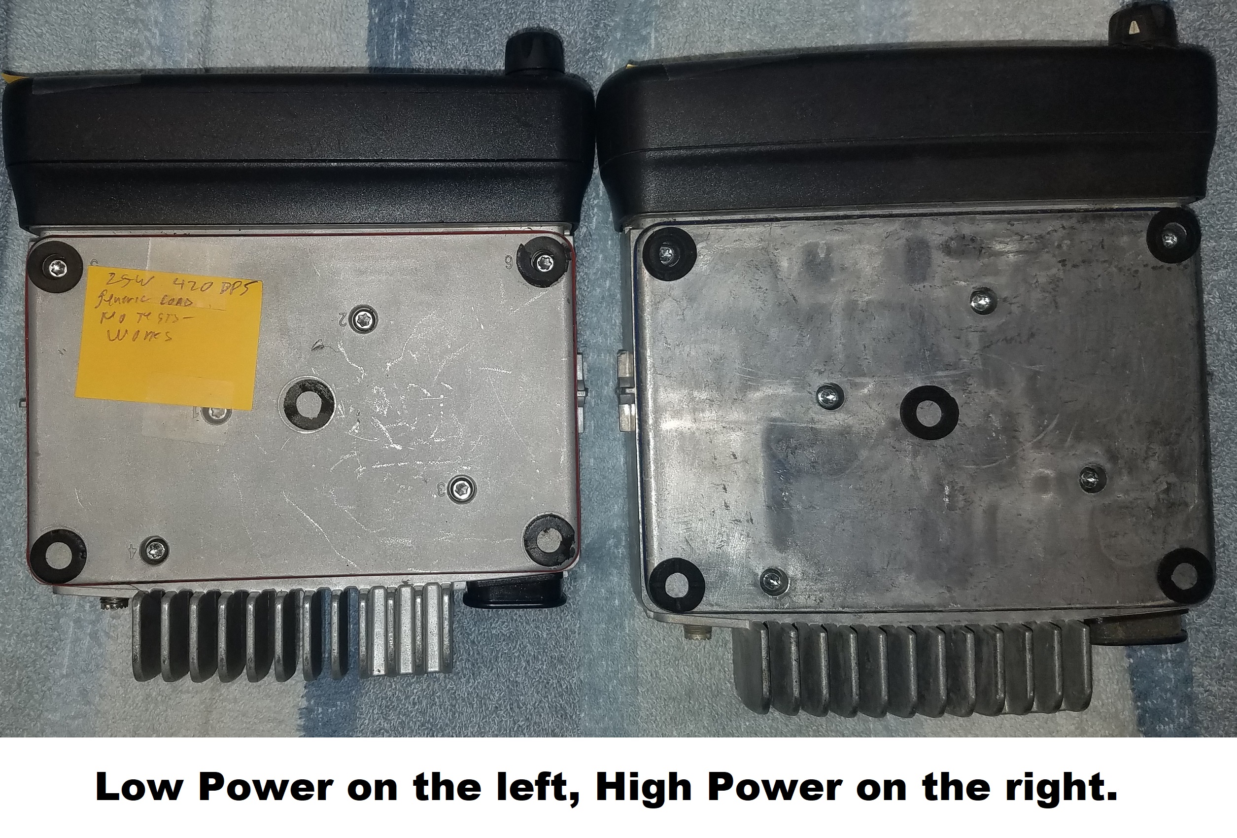
The CDM radio bodies were made in three low band ranges: 29.7 to 36 MHz (the "B"
range), 36 to 42 MHz (the "C" range), 42 to 50 MHz (the "D" range),
one high band (VHF) range: 136 to 174 MHz (the "K" range), and two UHF
ranges: 403 to 470 MHz (the "R" or "UHF 1" range) and
450 to 512 MHz (the "S" or "UHF 2" range). One piece of sales literature
referred to the "K" range as 132-174 MHz, but I think that was either an error or a special
batch that was made for the military. The low band bodies are a larger physical size (and use a different mounting bracket from the VHF and UHF models). They were made in one power range of 40 to 60 watts where the VHF and UHF bodies were made in two power levels: the low power (1 to 25 watts) and the high power (25 to 45 watts). The high power radios are a little larger than the low power radios (photo). Note: At the time of this writing your author does not have any hands-on experience with the low band CDM radios, but he's been told that "the low band 42-50 MHz radios can be stretched to 54 MHz but they do not work right unless you move the tuning posts and do a complete Tuner alignment afterward". Look at the procedure for moving the "200" MHz units to the amateur band. |
|||||||||||||||||||||||||||||||||||||||||||||
|
|
You want to use Tuner R02.00.03 and NOT R02.15.00 or later. The later revisions are narrowband locked and does not allow the 20/25 KHz channel spacing modes (the softpot adjustments are greyed out and not accessable / adjustable). If you can't find R02.00.03 then try using the Winabler utility to re-enable those softpots. | |||||||||||||||||||||||||||||||||||||||||||||
|
|
CDMs are prone to have a transmit audio noise that sometimes resembles alternator whine, but at
a constant unchanging frequency. Well, Motorola's production line had a screw loose. Or actually
multiple of the T20 Torx™ cover screws loose. Multiple reports exist from fleet purchasers of
brand new radios being received with all of the six screws in the cover anywhere from 1/4 turn
to 2 turns loose. The screws are numbered on the cover. Simply tighten the screws, in sequence,
to torque tight. I'll repeat myself - If you have a whiny radio and find one cover screw loose, then back them all off a turn or two and then torque in the numbered order. If you have to open the radio then open it in reverse order and do not forget to pull the black accessory plug housing out of the back of the chassis before lifting the board out of the housing. When installing the top cover, lightly run the screws in first to position and settle the plate, then torque them in numerical order as outlined in the manual. This is necessary to insure proper pressure on the thermal pad for the PA and other heat generating devices inside. |
|||||||||||||||||||||||||||||||||||||||||||||
|
|
The internal speaker of the CDM is 22 ohms and rated at 5 watts. The prior GM300
and Maxtrac models had a jumper in the accessory plug that when removed disabled the internal speaker.
That option does not exist on the CDM, you have to disassemble the head to disable the speaker. You
can use a GM300, Micor or Motrac mobile speaker just by connecting it to pins 1 and 16. NOTE: The speaker audio outputs – pins 1 and 16 – of the CDM float both sides above ground. DO NOT ground (even for a moment) either pin 1 or pin 16. You WILL destroy the audio output stage and Moto no longer has that part. |
|||||||||||||||||||||||||||||||||||||||||||||
|
|
The factory Ignition Sense cable is the HKN9327. It has a standard ATO automotive fuse holder
in line and ships with a 4 amp fuse. Don't use it! The Ignition Sense line (pin 10 on the acecssory plug)
is one of the few weak spots in the CDM design. The Ignition Sense line pulls only a few milliamps of curernt
and is NOT well protected from vehicle electronic noise or crud. Even a 1 amp fuse is too much. Personally, I avoid using pin 10 at all and use the pin 9 to pin 7 jumper trick (documented elsewhere on this page) to get the CDM to power itself up when DC power is applied to the rear connector. This automatic-power-up is mandatory for control receivers, repeater receivers, repeater exciters, link radios, or remote base radios. |
|||||||||||||||||||||||||||||||||||||||||||||
|
|
The CDM has an internal fuse. It's NOT mentioned in the Basic Service Manual, but it IS mentioned in the Detailed Service Manual. Referring to that manual Chapter 3: page 1-3, says (on the last line on the page) "Fuse F0401 prevents damage of the board in case the FLT A+ line is shorted at the control head connector." Chapter 3: page 3-8 is a schematic. Look at the top left – the control head connector. Find pin 10 and follow it to the source (on the right). It says "Note: Fuse is part of PCB. In case fuse is blowen, replace it with R0410 P/N 0662057B47". Yes, they are using a trace on the PCB itself as a fuse. Yes, the schematic says "blowen". And the parts list says that R0410 is Moto part number 6580542Z01, described as "FUSE 3A". Look at the board behind the control head. That's where the "fuse" is. I'd suggest that you NOT bridge the fusible trace with a piece of wire. A shorted head will melt a trace elsewhere, and and that new spot may not be accessible. Just solder a 3 amp fuse acoss the blown trace. Back in the 1970s I watched WA6KLA (SK) take apart a 3AG glass fuse (heat each of the two metal end caps until the glue fails), salvage the fuse wire and using tweezers to hold the fuse wire he tack soldered it across a blown trace on a Motrac radio. | |||||||||||||||||||||||||||||||||||||||||||||
|
|
You CAN have a microphone connected to the accessory connector of a CDM. Just make up a
cable using an 8 pin RJ45 jack on one end and connected to a 16-pin or 20-pin accessory plug
as follows (note that the ethernet numbering is backwards from Motorola numbering):
Radio Configuration -> Accessory Pins tab -> Accessory Package: Default (which makes accessory connector pin 3 an External Mic PTT Input, Active Level = Low, and Debounce Enable checked). Radio Configuration -> Accessory Pins tab -> Set pin 6 as Mic Off Hook (Input), Active Level = Low, and Debounce Enable checked. Then Radio Configuration -> Accessory Configuration tab -> set External PTT Audio Source: Ext Mic Audio |
|||||||||||||||||||||||||||||||||||||||||||||
Articles, Modifications and Other Information:
|
|
CDM Product Line Model Number Decoder 473 KB PDF. This was compiled by Mike WA6ILQ using information from the Basic and Detailed service manuals listed below. If the first two letters of the model number are "AA" they are USA region radios and are FCC approved. If the first two letters are "LA" they are radios made for latin america and are not FCC approved (and the USA Depots won't touch them). If anyone has any of the other region codes please send an email to the page maintainer. |
|
|
The CDM-series rear panel Accessory Connector by Robert W. Meister WA1MIK (SK) Note that the pin numbering is NOT what you would expect… They added a pair of pins on each side of the Maxtrac / GM300 16 pin connector… |
|
|
How to Remove a Motorola UHF CDM 1250/1550 Password By Dennis Rogers N5VRP 107 KB PDF Dennis's radio group bought a CDM on eBay and found that it had a password… They got around it by "sniffing" the serial stream. While this prodedure was written about his experience with a CDM mobile this process will work on any Waris family radio, and that includes the HT750, the HT1250, and the HT1550 handhelds and also every radio on the list higher up on this page (next to "Programming the "Professional Series Radios"). |
|
|
There is an alternate method that will bypass the password and will let you view or overwrite the existing codeplug, but it requires knowledge and experience in hex editing the CPS executable file. If you know what you are doing in hexediting just open CPS 6.12.05 ProRadio.exe, then change offset 24DD69 from 74 to EB then save. Naturally, make a backup copy of your CPS first. If you have a different software revision look for the string 5B85C0742B and change it to 5B85C0EB2B (only the second last byte of that new string is different). Then run your hexedited CPS and when it asks for a password don't type anything, just hit "Enter". If you don't have a hex editor then go to https://hexed.it and experiment. |
|
|
A third method is available if you don't need to save the original codeplug. Just overwrite the password-locked codeplug in the radiowith a non-password-protected codeplug. The BIG "gotcha" is that the model number must be totally identical!! If you don't have or can't get a a non-password-protected exact same model number codeplug then load a blank codeplug into the radio using your CPS. If you need a blank codeplug there is a folder full of them, one for each possible model number in the SAMPLES directory of your CPS (but if you are going to be unlocking password protected radios you will want a copy of the SAMPLES directory from revision 6.12.09 (the last / final revision) as that revision has model numbers that are not in previous versions). Just don't write to your radio with 6.12.09 as it will lock you into narrowband. |
|
|
Making the CDM-series Radios Operate Out Of Band by Joel Huntley WA1ZYX (offsite link) This method requires just some simple hex-editing. |
|
|
Additional information regarding the above out of band mods 35
kB PDF by James Lawrence NA5RC Especially important if you are running CPS Revision 6.12.05, which you should be… |
|
|
Invalid Region Code error? 82 kB PDF by James Lawrence NA5RC Some CDMs sold on popular auction sites often come from foreign markets and can't be programmed with the standard software distributed in North America. The CPS throws up a big error message. Here's a simple fix using RegEdit (which comes with Windows) to remove the region limit. |
|
|
Rebanding the "200" MHz CDM mobiles 724 MB PDF by
By Mary Warrington VE3OML and Graham Warrington VE3WGW The "200" MHz CDM was available only as a CDM-1550 for the Automated Maritime Telecommunications System (AMTS). (off-site pointer – opens in a new browser tab) and other adjacent (in frequency) services. This is a step-by-step procedure that converts the 217-222 MHz narrowband 16 channel CDM with 12.5 KHz steps to a 222-225 MHz wideband CDM with 128 channels on selectable 12.5 / 20 / 25 KHz steps. The procedure includes changing the IF filters, using the waris.py software module to switch to wideband, changing the frequency limits to 222-225 MHz, 128 channels, changing the Tuning Piers, the Test Modes, warping the Reference Oscillator, setting the Modulation Balance, the Deviation and the Squelch. |
Manuals, Brochures, Guides, and Other Printed Material:
|
|
CDM series brochure 1.8 MB PDF Covers the CDM750, CDM1250, CDM1550, CDM1550LS+ models on low band, VHF, UHF, 200, 700 MHz. 2014 vintage. |
|
|
Motorola CDM Series Product Overview 3.3 MB PDF This is a sales document produced to go along with the introduction of the CDM mobiles in 1999. |
|
|
CDM Series "MotoTurbo" Product Brochure 542KB PDF This is one of the official "Professional Series" mobiles product brochures. Not shown is the CDR700 update to the dual-GM300-based GR300 tabletop repeater or the dual-CDM CDR500 replacement for the wall-mount GR500. CDR500 External Photo CDR500 Internal Photo CDR700 photo 1 and CDR700 photo 2. Both could be configured as in-band repeat, one-way-crossband-repeat or bidirectional-crossband-repeat. The available acccessory modules that fit into the CDR500 or the top slot of the CDR700 are mostly the same as offered in the GR300 / GR500. |
|
|
Standardized Display Nomenclature on the CDM1250 and CDM1550
series radios By Matt Lechliter W6XC 560 KB PDF The CDM1250 and CDM1550 have a 14 character LCD display. Here's how one system uses it on their repeater and link radios. |
|
|
CDM and PRO-series Basic Service Manual 3.8 MB PDF This basic manual covers all CDM and PRO series mobile radios. 6881091C62-E 2012 vintage. |
|
|
CDM and PRO-series Detailed Service Manual Ver: C 30.1 MB PDF This manual covers the Low band, VHF and UHF CDM and PRO series mobile radios. 6881091C63-C 2007 vintage. We also have the "B" version for those that are looking for it 16.9 MB PDF. |
|
|
CDR500 Wall Mount
Repeater & CDR700 Desktop Repeater Service/Programming Manual 1.84 MB PDF 6864110R66-O 2001 vintage. Motorola used dual CDMs to replace the dual GM300s in the GR500 and renamed the box as the CDR500. Likewise the tabletop GR300 repeater became the CDR700. This manual was the guide to the field upgrade kits. NOTE: This manual has almost nothing on the internals of the CDM radios however it does have a lot of info on the interfacing to the CDMs, plus info on the various add-in controllers: the RICK (HLN3333), ZR310, i20R, ZR340, HPN9005, HKPN4000, HKPN4001 and the HKN9033. |
|
|
CDM-series Remote Mount Kit RLN4801 & RLN4802
400 kB PDF 6864110B51-A 2002 vintage. These kits are the control head extension kits for all CDM-series and some CDM-based GM-series mobile radios. The RLN4801 is for the CDM750, the RLN4802 is for the CDM1250 and CDM1550 models. The kits DO NOT include the 10-conductor(!) cable between the head and the radio - that must be ordered separately. While you would think that a common Ethernet cable would work it won't! The available cables are: 3 meters (9.8 feet) RKN4077, 5 meters (16.4 feet) RKN4078, and 7 meters (22.9 feet) RKN4079. Page 3 of the PDF has more information. |
|
|
CDM750 User Guide 1 MB PDF Not band specific. 6881091C54-A 2003 vintage. |
|
|
CDM750 Specification Sheet 145 kB PDF Low Band, VHF and UHF. 2012 vintage. |
|
|
CDM1250 User Guide 1.3 MB PDF Not band specific. 6881091C55-B 2003 vintage. |
|
|
CDM1250 Specification Sheet 60 kB PDF Low Band, VHF and UHF. 2006 vintage. |
|
|
CDM1550 Brochure 607 kB PDF VHF, UHF, 200 and 700 MHz. 2003 vintage. |
|
|
CDM1550 User Guide 1.3 MB PDF Not band specific. |
|
|
CDM Series Control Station
Service and Installation Manual 3.99 MB PDF This manual covers the Control Station (commercial base station) - a CDM in a box with a power supply. Not band specific. 6880309N15-A This manual has a section on interfacing the CDM to the Control Station Interface Module (CISM) – the CDM version of the R.I.C.K and that section can be useful in connecting the CDM to an external repeater controller. |
|
|
Low Band CDM1550 Specification Sheet 90 kB PDF |
|
|
"200" MHz CDM1550LS+ User Manual 6864110R13-O 2.85 MB PDF The 220 MHz CDM was available ONLY as a CDM-1550. |
|
|
CDM1550LS+ 200 and 700 MHz Basic Service Manual (6864110R16 - we don't have this one yet, anyone have a PDF?) This manual covers both the 200 MHz (model AAM25MHF4DP5AN) and 700 MHz CDM1550 LS+ (model AAM255HF4DP5AN) radios. The "200" MHz model was the 25 watt 217-222 MHz CDM1550LS+ (model AAM25MHF4DP5AN) radio that was made only in narrowband and 12.5 KHz channel spacing. They didn't even install the wideband receive parts. It CAN be moved to the 219-225 MHz amateur band, but you will need to acquire wideband IF filters and swap them, and then do some software / firmware tweaks to move the band edges and enable 20 KHz channel spacing. Note that the original wideband surface-mount filter (that was custom-made by Murata for Motorola) is no longer available but it can be scavenged from a dead VHF or UHF hulk, or you can use a differently packaged but electrically similar unit. More info in the "CDM Notes" article above. |
|
|
CDM1550LS+ 200 & 700 MHz Detailed
Service Manual 6864110R14-O 55.8 MB PDF This manual covers the 200 MHz (model AAM25MHF4DP5AN) and 700 MHz CDM1550 LS+ (model AAM255HF4DP5AN) radios. |
CDM Accessories:
This is what the spec sheets recommend:
|
|
AARMN4025 Standard Compact Microphone (but your existing Maxtrac / Radius / GM300 microphone will work just fine) |
|
|
AARMN4026 Enhanced DTMF Keypad Microphone This 12-button DTMF mic has a 10-pin RJ-45-style plug and will not work correctly on anything other than a CDM. |
|
|
AARMN4038 Heavy Duty Microphone |
|
|
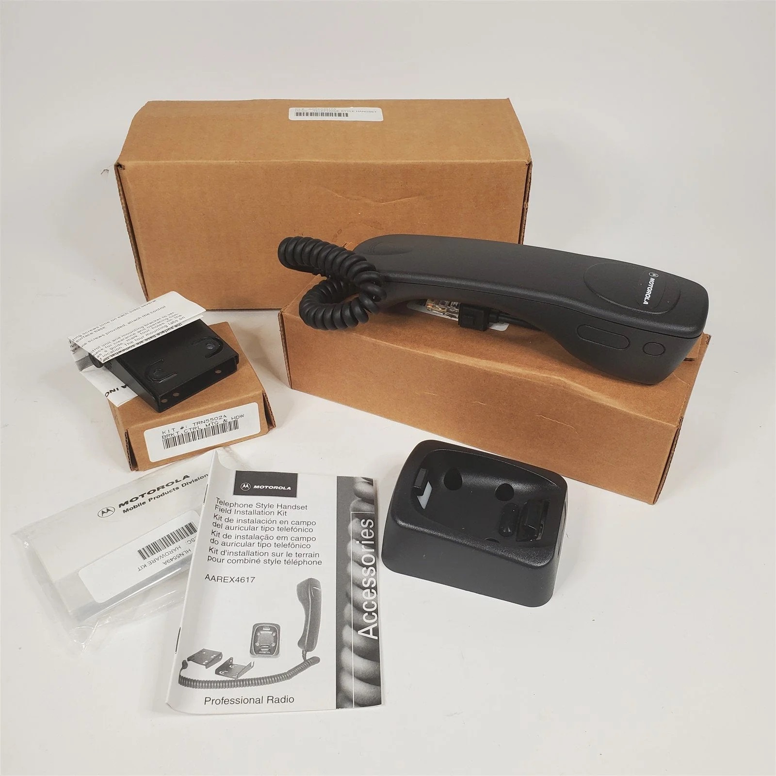
AAREX4617 Telephone Style Handset with Hang-Up Cup This unit is also compatible with CM200 / CM300 / PM400 but is not for use with dual control heads. Includes RLN4756 Handset with Coiled Cord, NTN8378 Hang-up Clip, TRN5502 Mounting Bracket, and HLN5549 Mounting Bracket Hardware |
|
|
HMN3000B Desk Mike for control stations 3 MB PDF Of course this has been discontinued but was replaced by the RMN5068A. |
|
|
RSN4001 13 Watt External Loudspeaker |
|
|
HSN8145 7.5 Watt External Speaker |
|
|
GLN7324 Standard Low Profile Bracket (VHF/UHF) This will not work on a low band CDM. |
|
|
GLN7317 High Profile Mounting Bracket (VHF/UHF) This will not work on a low band CDM. |
|
|
RLN4779 Key Lock Mounting Bracket (VHF/UHF) This will not work on a low band CDM. |
|
|
CDR500 and CDR700 Accessories 93 kB PDF The wallmount CDR500 and desktop / tabletop CDR700 prepackaged repeaters were based on dual CDM750s but have been seen with any combination of CDM750s, 1250s or 1550s (or even a GM300 receiver and a CDM750 transmitter. The various items listed in this document are relevant to both the CDM radio and for the CDR500 and the CDR700. |
|
|
CDM750, CDM1250, CDM1550 Parts Lists and Accessories 381 kB PDF |
Final Notes:
|
|
As posted at the top of this page, I offered to post any tips / tricks / gotcha's. Carl VA2CMB posted on the repeater-builder mailing list that: ...he had a low band CDM-1250 that had multiple issues...Here's one emailed response: IF you have a CDM wired up through the accessory connector to an external controller, and you have Ignition Sense set to the default ON/Off OR Ignition there is a potential problem. If you push the front panel on-off button while the external controller has the radio transmitting then the radio will APPEAR to turn off - BUT IT DOES NOT TURN OFF! It goes into an uncontrolled mode and draws several amps. This is VERY messy. Usually you have to make a trip to the site and unplug power from the radio to clear the problem. Here's another emailed response: BTW I would NEVER separate the control head from the attachment spacer ring unless you must for a repair. Take the adapter frame off the radio and leave the head assembly intact. Unplug the ribbon from the radio end. Note the big black dot on the ribbon cable and the 0 on the radio casting and match them up. Here's another emailed response: I had a CDM that would not go into Boot Mode and found that the front power button MUST be programed in CPS for ON/OFF & IGNITION for the flash to work, this CDM was set for ignition only. I changed it and it flashed with no problem. When you run the firmware update program, the radio should be on and the HLN9742 adapter switch should be in the center (off) position. Run the program and follow the instructions on the screen. It will tell you to throw the switch to the B position and then hit the power button on the radio twice, pausing at least one second between presses. After doing that, click OK (or upgrade, I forget what it actually says) and you are off and running. I also do not think anyone mentioned that the radio turns off in the first press of the power button and remains with the display blank during the rest of the flash update. The display does not return untill you power the radio down and back up again at the end of the flash. Here's yet another: CDM Radios made before a certain date have several major flaws. |
|
|
If anyone has additional hints / tricks / gotcha's, manuals or documents I'd be happy to post them here. You can be credited or anonymous, your choice. |
Back to the top of the page
Motorola index
Back to Home
Originally this information was on a combined CDM / CM page that was created in October of 2016 by Mike Morris WA6ILQ.
The CM series material was relocated to its own page in October of 2021.
This web page, this web site, the information presented in and on its pages and in these modifications and conversions is © Copyrighted 1995 and (date of last update) by Kevin Custer W3KKC and multiple originating authors. All Rights Reserved, including that of paper and web publication elsewhere.
