One of the things we are looking for is the schematic of the Motorola CDN6351A cable (possibly CDN6321A) to connect external equipment to a paging or repeating station like the MTR2000, PURC5000 or MSF5000. That cable was originally designed by Zetron as their part number 950-9919 and has an integrated summing amplifier that mixes multiple sources (like a paging encoder and a local microphone) into a single output. At one point it was priced at over US$300. If anyone has one sitting on a shelf we'd like to borrow the included paperwork for scanning for this web page.
Note that the MSF5000 was the USA repeater / base station and the MSF10000 was
the export version. The PURC5000 was an MSF-based paging station that replaced the
MICOR-based PURC paging station and you should look on the MICOR pages at this
web site for information on it.
 |
Please note that interfacing techniques are pretty-much band
independent and while one author may have interfaced a brand X controller to
a VHF unit his methods will work on a UHF unit also. Just remember that some
MSFs are powered by 24 volts and others are powered by 12 volts... |
|
|
Most of the audio circuitry inside the MSF5000 Control Tray is
DC-coupled, is powered by +9.6 volts DC, and is biased at 1/2 VCC
(i.e. at +4.8 volts DC).
If you will be connecting anything directly to the TX or RX Audio stages on the
control board, you need to add a 10µF 16 volt electrolytic capacitor
in series with your audio signals with the positive side towards the control board.
Many of the unused signals are connected to this +4.8 volt bias using
push-on jumpers. If you remove a jumper you may have to also bias the signal
to another source of bias voltage through a 10 k ohm or higher value resistor. |
|
|
You should verify that the 3-pin 2-way jumpers on the SSCB
and TTRC are set to their default positions before doing any interfacing. The
articles below make no mention of these jumpers unless they have to be changed.
The default position is indicated by a white silk-screened bracket over or near
the jumper. The TTRC schematic shows jumpers with "A" and "B" positions; "A" is
the normal or default position; "B" is the alternate position. |
 |
Interfacing the Masters Communications
RA-42 to an MSF5000 By Steve Arntz KM5HT
Everything you need to know about connecting the
RA-42 USB AllStar radio adapter interface to an MSF. |
|
|
MSF5000 Interface
Signals By Robert W. Meister WA1MIK
Everything you wanted to know about the available signals an external controller
could use, but didn't know whom to ask... |
|
|
Interfacing the MSF5000 to a
CAT 200 or CAT 250 Repeater Controller By Robert W. Meister WA1MIK
Yet another method of connecting an external controller to a digital station. |
|
|
Interfacing an Analog MSF5000
Station to a Repeater Controller By Jim Reese WD5IYT; 240 kB PDF file.
While Jim is interfacing an analog station to a home-brew controller the basic
concept is useful - as long as you have the right voltages COR is COR no matter
if it's a home-brew controller or an NHRC, a Link / RLC or an S-Com, etc. |
|
|
Interfacing an Analog MSF5000
Station to an RLC Repeater Controller By Author Unknown; 75 kB PDF file.
Another user's interfacing information, oriented towards the analog MSF5000 and
the RLC repeater controllers. |
|
|
MRTI Interface Cable
Documentation By Robert W. Meister WA1MIK
This article describes how a real MRTI interface cable connects to the MSF5000 station.
Pin numbers, wire colors, and signal names for both ends. Not documented elsewhere. |
|
|
ACC RC-850 Interfacing
to an MSF5000 station 160 kB PDF from an unknown source.
While oriented towards connecting an ACC RC-850 to a CXB series MSF5000, there is good
information on connecting to any controller. |
|
|
ACC RC-850 Interfacing
to an MSF5000 station Transcribed by WA1MIK.
A somewhat updated and corrected HTML version of the above article, although there is
still a lot of information missing, like all the RSS settings for the MSF5000 and the
configuration for the RC-850. While initially done for a VHF station, the information
is suitable for any MSF5000 analog-plus or digital-capable station. |
|
|
MSF5000 Analog Repeater
Interfacing By Paul Blum K9ARF
Information on many of the available input and output signals, including a rather
unique way to access some of the hidden PTT signals from your repeater controller.
This same idea can be used to access other MUXBus signals as well. |
|
|
MSF5000 Standardized
Repeater Interfacing By Matt Lechliter W6KGB
Yet another method of developing a standardized interface, for both analog and digital
stations.
|
|
|
Interfacing
external repeater controllers to the analog MSF5000 repeater By David
Rudd AI4JI
A simple method of connecting an external controller to an analog station.
This article was here, then removed after the web site went away. It's back becasue a copy (dated January 2020)
was found at the Wayback Machine.
|
|
|
Interfacing an S-Com 7330 to an MSF5000
digital-capable station By Justin Reed NØUJQ; 419 kB PDF file.
Yet another method of connecting an external controller to an MSF5000 station. Someone found this article
on the web and sent it to us anonymously. Includes an addendum that explains why the Gen Tx Data
inputs may not work initially and a couple of ways to fix this situation. |
|
|
Adding Simple DTMF On/Off Control to an
MSF5000 900 MHz Station by Robert W. Meister WA1MIK
Multi-digit DTMF control was desired for the New Jersey repeaters. Initially designed
to work on a digital-capable MSF5000 station with a TTRC, you could adapt the
connections to work on an analog or digital station without requiring a TTRC. |
|
|
A summary of Interfacing
Information for the Analog MSF5000 stations by Robert W. Meister WA1MIK
A collection of the minimal signals needed to interface an external repeater
controller to the analog (CLB) stations. Companion to the article below. |
|
|
A summary of Interfacing
Information for the Digital MSF5000 stations by Robert W. Meister WA1MIK
A collection of the minimal signals needed to interface an external repeater
controller to the digital (CXB) stations. Companion to the article above. |
|
|
Digital-Capable and Analog-Plus
SSCB Signal List compiled by Robert W. Meister WA1MIK
The schematic diagram for the SSCB is nine pages long, and all but one fold out.
Signals jump around from sheet to sheet and it's hard to figure out where they all
go or come from. One day many years ago I got tired of searching so I marked my
schematic and transcribed the information. Recently I added all the signals that
come and go via the SSCB connectors. The tables in this article go along with the
schematic diagram, a 460 kB PDF file; a link to it can be found in the article or
here. |
 |
The above interfacing articles are representative of several different
repeater controller models. If your particular model isn't listed above, that doesn't
mean it can't be interfaced to an MSF5000 station. Most controllers require the same
five or six basic signals plus ground and controller power. There is sufficient information
in the articles above to let you mix and match controllers from all major manufacturers. |
|
|
You should verify that the 3-pin 2-way jumpers on the SSCB
and TTRC are set to their default positions before doing any modifications. The
articles below make no mention of these jumpers unless they have to be changed.
The default position is indicated by a white silk-screened bracket over or near
the jumper. |
|
|
Extracting Boards from the MSF5000
Plastic Control Tray by Robert W. Meister WA1MIK
It's not obvious how to get the boards out of the tray and the 20+ year old plastic is brittle
and easily broken. This article gives you the secrets of how to physically remove the SSCB
or TTRC boards from analog or digital MSF5000 or PURC5000 stations. |
|
|
Removing a Secure board
from an MSF5000 station by Robert W. Meister WA1MIK
A simple step-by-step procedure that tells you how to electronically and physically
remove the secure board from a digital-capable station. Also applicable to disconnecting
the TTRC board. Read the above article first(!) to physically extract the SSCB or TTRC boards. |
|
|
How to get a CXB Secure-capable
Station Control Board to work in a CLB station by Robert W. Meister WA1MIK
The CLB station can be upgraded with an SSCB board (the CXB control board) which
converts it from an EPROM to RSS programming, but you need to get +5vDC to the
rest of the station. This article tells you why this is so, and how to fix it. |
|
|
How to use the MSF5000
power amplifier stand-alone by Robert W. Meister WA1MIK
Enough people have asked how to do this. Not much to it, just a few precautions.
Put that spare VHF, UHF, or 900 MHz power amp and power supply to good use. |
|
|
How to make the MSF5000 work
without a power amplifier by Robert W. Meister WA1MIK
This is complementary to the previous article. It explains what I did to get a
digital-capable UHF station to transmit without its power amplifier attached. |
|
|
MSF5000 PA Molex Connectors
By Robert W. Meister WA1MIK
Documentation for the 6-pin Molex connector wiring for the cables that run between
the power amplifiers and the RF Tray. |
|
|
Accessing the electronic
adjustments in the digital-capable MSF5000 station by Robert
W. Meister WA1MIK
A quick summary of the EEPots and how to adjust them via RSS or the front panel. |
|
|
Making VHF VCOs go down to 144
MHz by Scott Hilton NØOBA and Paul Thompson WØOD
These fellows had several range-2 stations that just refused to operate below 146 MHz.
They found a rather easy modification to the VCOs that results in coverage down to
144 MHz. |
|
|
Reducing the PL Deviation of MSF5000
Stations by Robert W. Meister WA1MIK
If your station's PL deviation level is too high, there's no pot you can adjust
to change it. You can reduce the PL deviation by adding one or two resistors (or the
missing pot) on the top of the control board. There's info here for both the analog
(CLB) and digital (CXB) stations. |
|
|
Connecting Fans to MSF5000 Stations
by Robert W. Meister WA1MIK
Often these stations had fans that were removed (cable and all) or you want to add a
fan to a station that never had one. Several people asked where to connect the cable.
This article shows you the elusive DC fan power connection points, obvious once you
know where to look. |
|
|
Building an MSF5000 Adapter
Cable for the R1033 Test Set by Anthony Stump KE4KQI
Here's a simple to make adapter cable that lets you use an R1033 test set with an
MSF5000 station. It's better than lugging multiple test sets around, especially if
you've got other stations that already use the R1033 test set. |
|
|
Adding a Preamp to an MSF5000 Station
by Robert W. Meister WA1MIK
A preamp can often improve a repeater's reception, but too much gain will cause more
harm than good. This article shows several configurations and explains why you need
to be careful when adding a preamp, and what you can do to reduce the gain. |
|
|
Replacing the Electrolytic Capacitors
on the MSF5000 Uniboard and Injection Amplifier by Robert W. Meister WA1MIK
All sorts of odd problems can crop up, such as the VCOs not locking, the receiver hearing
strange signals, etc. These are often due to failing electrolytic capacitors on the Uniboard.
After 20 years, these are starting to go bad. A parts list is provided. You might as well
replace the two electrolytic caps on the injection amplifier if your station has some. |
|
|
Replacing the Pots on the MSF5000
Uniboard by Robert W. Meister WA1MIK
The pots WILL go bad or break eventually. This article shows you some replacements,
which one to choose, and why. A parts list is provided. You might as well replace the
electrolytic capacitors while you've got the board out; see the "caps" article above. |
|
|
Replacing the Tantalum Capacitors on
the MSF5000 IPA/REG Board by Robert W. Meister WA1MIK
These caps often short out, catch fire, and will burn up a foil trace on the Uniboard.
They can easily be replaced and you should do this before they go bad and cause
major damage. |
|
|
Replacing the Electrolytic Capacitor on
the MSF5000 Inter-Connect Board by Robert W. Meister WA1MIK
It's just one cap on the 5 volt DC line, but you have to take a lot apart to get
to it, as it's under the RF Tray. |
|
|
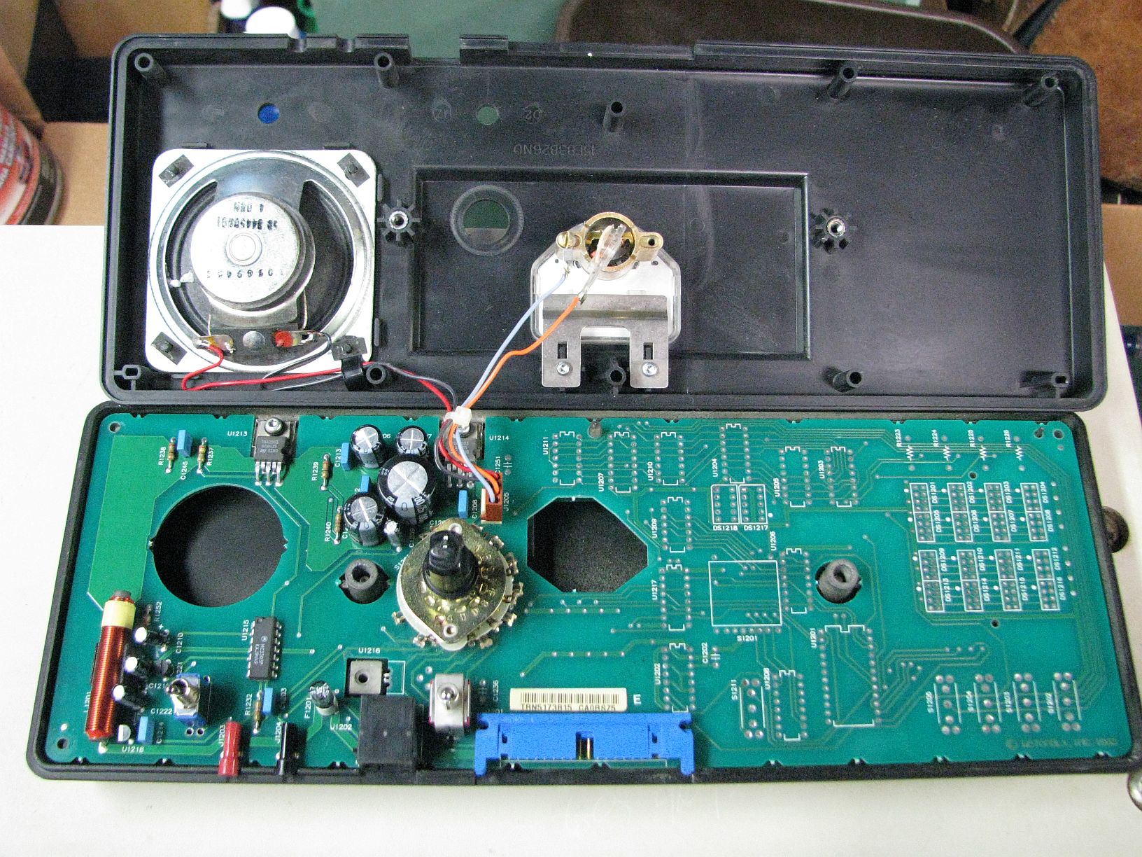
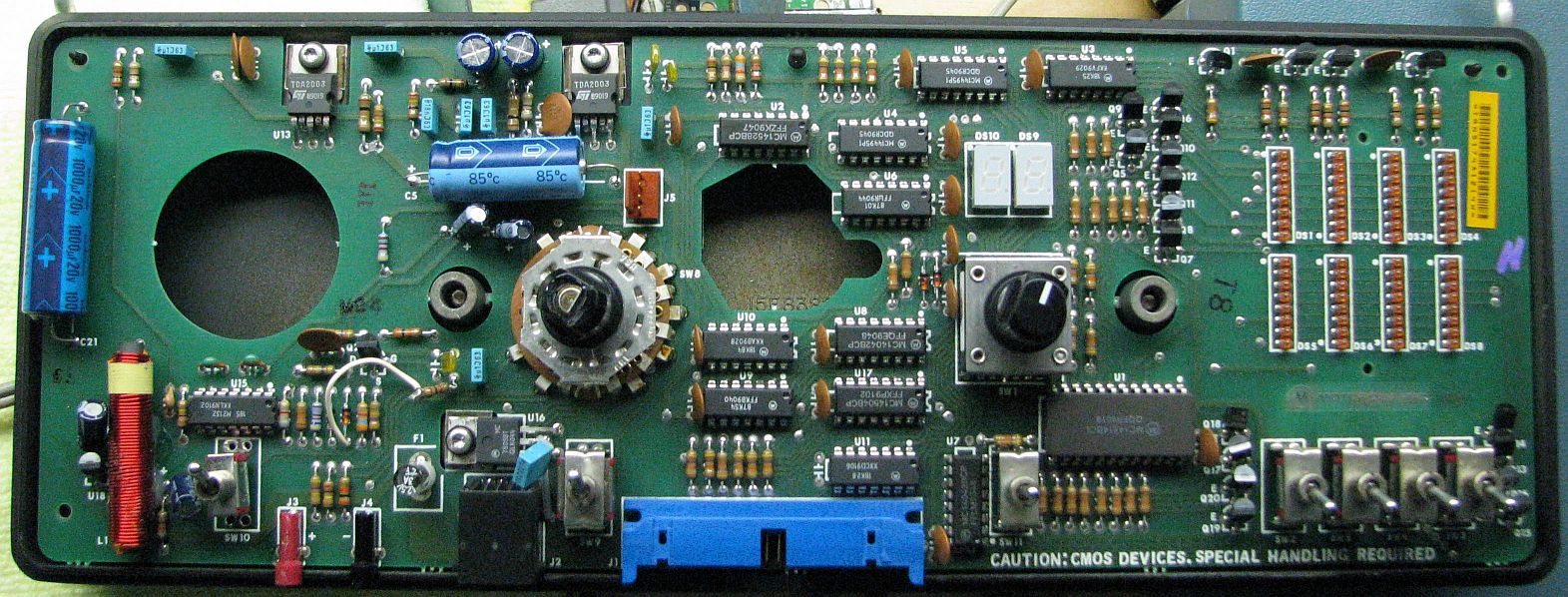
There are a few electrolytic capacitors on the MSF5000 digital-capable
Secure Station Control Board (SSCB) and Trunked Tone Remote Control board (TTRC), mainly
used for power supply bypass and audio coupling. There are also several on the analog
Station Control Module (SCM) in the power supply section. Any of these can leak. There
is currently no article covering replacement of these capacitors mainly due to the
different models of boards as well as the difficulty of removing and reinstalling the
front escutcheons and boards in the plastic control tray. |
|
|
Product Support Bulletins
A collection of Product Support Bulletins (PSBs) for the MSF5000 and PURC5000 stations.
Many of these PSBs offered board replacement, but since these stations are discontinued and
support and parts are no longer available, you're on your own as far as these changes go. |
A few enterprising people have figured out SOME of the code plug layout and even have a
program that will modify some items in the EPROM.
This web page has the information.
The following commercial businesses or private individuals claim to provide analog station
EPROM programming services. You may have to send some your old EPROM (2732 family chips are
starting to become pure unobtanium). If you have your own EPROM burner and chips you can ask
them to email you a PROM image file. If anyone has figured out the layout of the bits in the
PROM please let us know.
Note that (supposedly) VHF station code plugs can only be made at the Motorola factory or
repair depot; the suitcase programmer is incapable of generating a code plug for any models
except UHF, 800, or 896 MHz (also known as 900 MHz). Likewise if you've figured out
how to burn a VHF PROM please let us know.
EPROM speed doesn't seem to be a big deal with the R1801 programmer. 2732A up through
2732F EPROMs should all work. Most people still have an ample supply of EPROMs they can
sell to prospective customers.
27C32 EPROMs may or may not work. It depends on the manufacturer and the
programming firmware and hardware. Some will do it, some won't.
If you have an existing EPROM, the programmer can read the info that's already there,
saving the person doing the work from keying in all the existing data, thus lowering the
programming cost. If the programmer supplies a new EPROM, he has to enter a lot more
information and therefore charge more for the time involved. Make sure you provide ALL
programming information to minimize the back-and-forth programming trips and expenses.
Contact any of these people via their web sites or e-mail addresses. All of them were
alive and well and still programming MSF5000s as of June 7, 2016. Some of these people
may give amateur radio operators a discount, if they mention this ahead of time. It never
hurts to ask nicely. Repeater-Builder makes no claims as to the reliability or quality of
the work performed by any of these operations.
Most of these manuals are No Longer Available from Motorola, or are limited to whatever
is remaining in inventory. A good portion of the list below is courtesy Eric Lemmon WB6FLY;
he provided us an update in June of 2009.
Some of the manuals sections labeled "...from The MSF5000 Instruction Manual for the
analog station only." are incomplete. That's what was sent to us. Remember that the Power
Amplifier, the Power Supply, and most of the RF Tray are the same on the analog and
digital-capable stations, so check some other manuals before giving up.
| Manual P/N |
Description, Assemblies, Modules, Options, File Size, etc. |
| 6806907L34 |
MSF5000 DTMF Encoder/Decoder module, Option C585AM-SP (this is for the CLB
"analog" stations). This board installs in an Expansion chassis. 2.8 MB
PDF file. |
| 6880310B31 |
RTL-4826C MSF5000 Station Control Code Plug Programming Manual. This is for the
suitcase programmer required for the CLB "analog" stations. 5.3 MB PDF file.
Another version, scanned by Jared K4JJL, can be found
here as a 4.5 MB PDF file. |
| 6881060E70 |
Control and Applications Manual |
| 6881061E95 |
PURC radio link receiver manual 72-76 MHz and 928-960 MHz |
| 6881062E70 |
Instruction Manual PURC Paging Base Station |
| 6881062E75
| Older UHF CLB (analog) Base / Repeater Instruction Manual. 2.5 MB PDF file. |
| 6881063E39 |
Standard AC Power Supply section (TPN1186A) from The MSF5000 Instruction Manual
for the analog station only. 5.7 MB PDF file.
The DC distribution board TRN7242 that's found in some of these supplies has been
scanned and can be found here as a 50 kB PDF file. |
| 6881063E47 |
Introduction section from The MSF5000 Instruction Manual for the analog station
only. 2.9 MB PDF file. |
| 6881063E48 |
Operation section from The MSF5000 Instruction Manual for the analog station
only. 800 kB PDF file. |
| 6881063E49 |
Installation section from The MSF5000 Instruction Manual for the analog station
only. 1.3 MB PDF file. |
| 6881063E51 |
Maintenance and Alignment section from The MSF5000 Instruction Manual for the
analog station only. 5.5 MB PDF file. |
| 6881063E52 |
Power Amplifier Deck section from The MSF5000 Instruction Manual for the analog
station only (TTE1450A series, TTE1460A series). 7.5 MB PDF file. |
| 6881063E61 |
Station Control Module section from The MSF5000 Instruction Manual for the
analog station only (TLN2423A). 9.8 MB PDF file. |
| 6881063E62 |
DC Remote Control Board section from The MSF5000 Instruction Manual for the
analog station only (TRN5191A, TRN5192A). 2.5 MB PDF file. |
| 6881063E68 |
RF Tray section from The MSF5000 Instruction Manual for the analog station
only (TUE1761A, TUE1762A, TUE1901A). Incomplete; covers TRN9880A Uniboard, TX VCO
TTE1470A, IPA/Reg TLE2230A series. 5.3 MB PDF file. |
| 6881063E69 |
Most of the UHF Front End section from a depot manual. Includes the Injection
Amplifier, front end preamp, preselector, image, and injection filters, 3.5 MB PDF
file. |
| 6881064E05 |
PURC5000 Paging Transmitter 928-932 MHz 50-150 watts Instruction Manual
The paging synthesizer section was scanned by Tom KB5DPE and subsequently cleaned
up and turned into a PDF file by Bob WA1MIK. This contains the High Stability Oscillator (HSO), 14.4 MHz
reference oscillator, digital modulator, and power supplies. This is NOT
the unit that came with the New Jersey GFB stations. It can be downloaded
as an 8.2 MB file here. |
| 6881064E10 |
Instruction Manual PURC5000 Receiver option |
| 6881064E70 |
Older 900 MHz (Moto's parts guide lists this as an 800 MHz manual, but it's really
a 900 MHz) Trunked/Repeater (150 watt CLB) Instruction Manual that has full schematics
of every assembly.
The Driver Power Amplifier (TTF1242B, TTF1243A) section of the manual has been scanned
and can be downloaded as a 2.4 MB PDF file here.
The Final Power Amplifier (TTF1212B, TTF1213A) section of the manual has been scanned
and can be downloaded as a 2.6 MB PDF file here. |
| 6881065E14 |
Tone Remote Control Board section (TLN2421A, TLN2422A) from The MSF5000 Instruction
Manual for the analog station only. 7.0 MB PDF file. |
| 6881065E70 |
MSF5000 Supplemental Manual UHF Phone Applications |
| 6881077E15 |
MSF5000 Supplemental Manual UHF 6-75W |
| 6881077E25 |
MSF5000 Repeater 850-860 / 905-915 MHz |
| 6881077E30 |
Instruction Manual PURC5000 Installation / Operation |
| 6881077E35 |
PURC5000 UHF Paging Transmitter Service Manual
Contains the service manual and a separate manual # 6881117E76-D titled "PURC and PURC
5000 Digital Wattmeter and Audio Delay Line" option C47 and option C770. |
| 6881077E40 |
Instruction Manual PURC5000 UHF Transmitter |
| 6881078E25 |
MSF5000 800 MHz (851-869 TX and 806-824 RX) Trunked and Repeater Service Manual |
| 6881078E40 |
MSF5000 Trunked Repeater Operations Manual |
| 6881079E95 |
MSF5000 Supplemental Manual UHF SECURE |
| 6881080E30 |
This "Options" manual is an expensive list of some of the available
options for the digital / analog station. It is not at all complete and not terribly
helpful once you own the system. |
| 6881080E80 |
MSF10000 VHF Base / Repeater Service Manual |
| 6881081E95 |
Instruction Manual MSF5000 SMARTWORKS
Anyone know what this is? |
| 6881082E05-A |
This is the Digital-Capable and Analog-Plus User Manual. It has station inter-cabling
diagrams for just about every possible configuration, plus description, operation, and
mounting instructions. 5.9 MB PDF file. |
| 6881082E10 |
The Moto internal web site calls this "OLDER CXB/RLB UHF INSTRUCTION MANUAL"; it
is actually the CXB / RLB UHF Service Manual. This is huge and worth trying to find
and has been replaced by the newer band-specific service manual. It contains schematics
and parts lists for EVERY unit (PA, PS, RF tray, Control tray) and has detailed theory
of operation sections. The SSCB section has been scanned and can be downloaded as a 3.6
MB PDF file here. It covers the TLN3043 (UHF), TLN3059
(VHF), and TLN3090 (800 MHz).
The Uniboard X-ray view page from this manual has been scanned and can be downloaded
as a 7.7 MB PDF file here. The rest of the
Uniboard is in a separate file below.
The Interconnect Board (under the RF Tray) section has been scanned and can be
downloaded as a 1.5 MB PDF file here. |
| 6881082E20 |
The Moto internal web site calls this "OLDER CXB/RLB VHF INSTRUCTION MANUAL"; it
is actually the CXB / RLB VHF Instruction Manual. This is huge and worth having if you
ever find one. It covers the 125 and 350 watt stations and has full schematics and parts
lists. Almost all of the IPA and 9.6V Regulator (TLD2641A, TLD2642A) section has been
scanned and can be downloaded as a 750 kB PDF file here.
Pieces of the (TRN7006A) Uniboard (X-ray view and parts list) have been scanned and can
be downloaded as a 5 MB PDF file here. It's
similar to the TRN7231A UHF Uniboard that can be found below, but it's lacking some parts,
probably dividers.
The range-1 receive VCO section (TRD1841A) has been scanned and can be downloaded as a 3 MB
PDF file here.
The range-2 receive VCO section (TRD1842A) has been scanned and can be downloaded as a 3.5 MB
PDF file here.
The range-1 transmit VCO section (TTD1731A) has been scanned and can be downloaded as a 5 MB
PDF file here.
The range-2 transmit VCO section (TTD1732A) has been scanned and can be downloaded as a 4 MB
PDF file here.
The VHF frequency synthesis section, including steering line voltage graphs, has been scanned
and can be downloaded as a 507 kB PDF file here.
Almost all of the 28 volt power supply (TPN1260A, TPN1265A) section has been scanned and
can be downloaded as a 1.9 MB PDF file here.
The interconnection diagram for the 350 watt repeater station has been scanned and can be
downloaded as a 100 kB PDF file here.
The 125 watt PA section from this manual has been scanned and can be downloaded as a 1.8
MB PDF file here. TLD2691A covers 132-158 MHz; TLD2692A
covers 146-174 MHz.
The 350 watt "final" PA section from this manual has been scanned and can be downloaded as
a 3.8 MB PDF file here. TLD2740A covers 146-174 MHz.
The RX Front End and Mixer Amplifier (schematic and color X-ray views) have been scanned
and can be downloaded as a 3.3 MB PDF file here.
The 350 watt base station is similar except it has an antenna relay. The 125 watt stations
have just one power supply and one power amplifier. |
| 6881082E90 |
Instruction Manual MSF5000 800 MHz JAPAN |
| 6881083E92 |
VHF/UHF SSCB section only, 2.2 MB PDF. This covers the TLN3182 (VHF, UHF NB),
TLN3188 (UHF), and TLN3189 (VHF) boards. |
| 6881084E25 |
Service Manual MSF5000 900 MHz Analog Plus |
| 6881084E45 |
MSF10000 UHF Service Manual |
| 6881084E50 |
MSF10000 Service Manual, VHF Digital |
| 6881084E75 |
Instruction Manual PURC5000 276-284 MHz |
| 6881084E80 |
Installation/Operation Manual PURC5000 w/Advanced Controller
Several sections or pieces thereof have been scanned by Bob WA1MIK:
Description, Operation, Menus (1.5 MB)
Station Configuration (400 kB)
Station Alignment (400 kB)
External Connections (72 kB)
Manual Revisions (315 kB)
Quick Reference Menu Guide (105 kB) |
| 6881087E60 |
MSF5000/10000 Data Station Smart Wildcard and Diagnostic Options Manual. Contains
options charts, installation, and configuration info on the RSSI Loop-back Combiner
board (used in Data and Diversity Reception stations) as well as the Station Access
Module (SAM). The SAM is a programmable wildcard. The SAM section (TLN3221B) of this
manual has been scanned and can be downloaded
here as a 2.8 MB PDF file. |
| 6881089E28 |
PURC 900 MHz 5W, 75W, 15W Station Inter-cabling diagram showing the Low Power
Control Head (LPCH) documented below. 173 kB PDF file.
An alternate version (cleaned up, with the pages ordered correctly) can be
downloaded here as a 199 kB PDF file. |
| 6881089E40 |
Instruction Manual ACB RETFIT MICOR/PURC |
| 6881089E69 |
PURC 900 MHz 5W Low Power Control Head (LPCH, TLF7060A) manual. Basically a
stand-alone forward power sensor that allows a station to operate without a PA or
DPA/FPA, turning it into a 5W station. While this came from a PURC manual, it should
also be usable on an MSF station. Used with the 6881089E28 inter-cabling diagram above.
121 kB PDF file. |
| 6881092E05 |
Installation Manual CXB / RLB, covers alignment, operation, limited circuit
theory, installation, error codes, specifications, etc., for all CXB and RLB models.
The entire alignment section has been scanned and can be downloaded as a 1.7 MB PDF
file here. The board jumpers section has been
scanned and can be downloaded as a 640 kB PDF file here.
The HSO/USHO section (TLN3024B, TLN3025C, TLN3242A) was scanned by Mark N9WYS and
subsequently turned into a PDF file by Bob WA1MIK. This contains the HSO, 14.4 MHz
reference oscillator, and power supplies. THIS is the unit that's in the
New Jersey 900 MHz GFB stations. It can be downloaded as a 2.7 MB file
here. |
| 6881092E75 |
Service Manual CXB / RLB VHF (Depot) |
| 6881092E80 |
Service Manual CXB / RLB UHF, covers alignment, operation, and minimal
troubleshooting, and has schematics, parts lists, and board layouts for the
Uniboard, front end, and control tray ONLY. It has nothing on the power amplifiers,
power supplies, intermediate power amplifiers, or VCOs. The Uniboard section
(TRN7231) of the manual, minus the color X-ray views, has been scanned and can be
downloaded as a 638 kB PDF file here. The X-ray
views are available as a separate file above.
The SSCB schematic diagram section has been scanned as a 460 kB PDF file which
can be found here. This covers the TLN3384 (VHF,
UHF NB), TLN3385 (VHF/UHF), TLN3386 (800 MHz), and TLN3387 (900 MHz) boards. |
| 6881092E85 |
Service Manual CXB / RLB 800 MHz |
| 6881092E90 |
Service Manual CXB / RLB 900 MHz, compliments of Brian Boyle
WBØYLE. 5.9 MB PDF file.
This is the entire manual and is as good a scan as I've ever seen, and all schematics
are full-width, full-page. Note that the original manual only had schematics for the
Control Tray (SSCB, TTRC, Secure boards), Uniboard, and Interconnect Board. The Power
Amplifier(s), Power Supplies, and everything else in the RF Tray is barely documented.
SSCB boards: TLN3384 (replaced TLN3182, TLN3183), TLN3385 (replaced TLN3189, TLN3319),
TLN3386 (replaced TLN3204, TLN33320?), TLN3387 (replaced TLN3205, TLN3342). TTRC boards:
TLN3312 (audio), TLN7754 (logic). Secure boards TLN3045, TLN3267. Uniboard (narrowband
2.5 kHz) models: TRN7197, TRN7881. Interconnect Board model: TRN7142.
The 900 MHz IPA/REG board (TLF1511A) parts list, x-ray view, and schematic can be
downloaded as a 2 MB PDF file here. |
| 6881094E30 |
Service Manual MSF5000 Power Supply
The one-page Power Supply Model Chart (matrix) has its own section and Motorola
thought it was SO important they didn't even include it in the manual's index.
That page, with model and kit (board/module) numbers,
has been scanned and can be found here as a 57 kB PDF file. Note that this manual
only covers the most current equipment so a lot of older (necessary) information is
missing. Motorola seems to have wanted owners to "Use The Force" to figure out some
things, because there are errors, omissions, and inconsistencies throughout the manual.
The relevant pages for the VHF 120VAC 28V/14VDC battery-charging power supply TPN1271B
have been scanned to a 3.9 MB PDF file that can be found here.
A few other pages for the UHF 120VAC 14VDC battery-charging power supply TPN1185B have
also been scanned to a 950 kB PDF file that can be found here.
From an email to repeater-builder:
This manual, which comes in a nice three-ring ring binder, contains tech data,
schematics, and parts lists for all power supplies used in MSF5000 stations. Sixteen
different AC-input power supplies are included, as well as two DC-input power supplies.
Battery reverting / charging supplies are also included. Curiously, the MSF5000 service
manuals that I have do not have power supply information in them, but include a phrase
like, "See the power supply manual for further information" without revealing the
publication number. |
| 6881111E17 |
Lightning Protection recommendations section from the MSF5000 Instruction
Manual for the analog station only. 381 kB PDF file. |
| 6881113E74 |
Battery Charging Power Supply TPN1185A, 500 watt, 60 Hz. Provides 14vDC at
up to 25 amps. This is used on 60-120 watt UHF, 800, and 896 MHz stations. This is just
one section of a much larger UHF manual. 5.2 MB PDF file.
A few other pages for the UHF 120VAC 14VDC battery-charging power supply TPN1185B have
also been scanned; a 950 kB PDF file can be found here. |
| 6881113E77 |
Chip Component Replacement section from The MSF5000 Instruction Manual for
the analog station only. 1.0 MB PDF file. |
| 6881113E78-B |
TMN6164A Handset for analog or digital-capable stations. 120 kB PDF file. |
| 6881114E40-C |
Wild Card - Option C232AA, AB, AG or C233AB when factory installed, or Model
QLN2914A when field installed. This option is frequently found on wireline controlled
stations. Covers TRN5175A and TRN9754A wild card boards. 6.5 MB PDF file.
Option C233AT-SP provides four relay outputs for various alarm conditions and is
documented as a 60kB PDF file here.
This file is present to tell you how to add these to a stock wild card. |
| 6881114E60-A |
Multi-Coded Squelch (MCS) module for the Analog (CLB) station. Option C369AA Factory
Installed; Option TLN2704A Field Installed. TLN2420A module. Scanned by Bob WA1MIK. 26.8
MB PDF. This is the full manual except for the huge troubleshooting flowchart. You need
a different manual for the digital-capable (CXB) stations. |
| 6881114E93-C |
Expansion Tray, Option C695, for MSF5000 and PURC5000. Mainly the power supply
(TRN5178A). 3.9 MB PDF file. |
| 6881115E11 |
2- and 4-wire remote options for CLB base and repeater stations. Seems to fit in
the expansion tray. |
| 6881116E71-B |
MSF5000/PURC5000 Remote Diagnostic RS-232 Interface. 1.1 MB PDF file.
Option C565. |
| 6881125E43 |
Instruction Manual PURC REM AUDIO OPT |
| 6881125E68 |
MSF5000/MSF10000 Digital Field Programming (RSS) User's Guide. 4.7 MB PDF file. |
| 6881125E82 |
TPN1271A/TPN1273A 675W Battery Charger Power Supply
This is the 28V/14V battery backup power supply used by the VHF stations.
Bob VE3DJ supplied the real manual section which was scanned and PDF'd by Bob WA1MIK
to a 3.7 MB file. There was also a Service Manual Revision (SMR-5936) that came with
that section; it can be found below. |
| 6881126E87-A |
Multi-Coded Squelch (MCS) Manual for digital-capable and analog-plus stations.
Everything except the Troubleshooting Flowchart. Scanned by Bob WA1MIK. 8.5 MB PDF.
You need a different manual for the analog (CLB) stations. |
| 6881127E31 |
User Manual MSF5K/2100 BSC (anybody know what this is?) |
| SMR-5772 |
New UHF PA model numbers and model sheets. 516 kB PDF file. |
| SMR-5844 |
SSCB models TLN3182A, TLN3188A, TLN3189A. 852 kB PDF file. |
| SMR-5892 |
SSCB models TLN3182B, TLN3189B, TLN3204B, TLN3205B. TTRC modules TLN3112B,
TLN3114B. Option C514 Transparent Operation Secure module TLN3045C. 2.84 MB PDF file. |
| SMR-5936 |
VHF 28V/14V battery charging power supplies TPN1271A/TPN1271B. Covers the slight
differences between the TPN1271A and B versions. 3.5 MB PDF file. |
There may be other manuals out there; contributions of additional numbers, PDFs
and descriptions are always welcome.
In May 2009, Motorola no longer had the firmware EPROM for the SSCB, TVN6055A.
They did still list the latest firmware EPROM for the TTRC, TVN6056A, for about
US$31. There's also no part number listed for the Secure board EPROM.
Does anyone have a good set of PROM image files?
Hand-coded HTML © Copyright 2006 and date of last update by Mike Morris
WA6ILQ and repeater-builder.com.
This page created 26-Mar-2006