Motorola index
Back to Home
Programming an MSF5000 to work with an external repeater controller through the MRTI interface
By Robert W. Meister WA1MIK

|
MSF index Motorola index Back to Home |
MSF5000 RSS Programming Programming an MSF5000 to work with an external repeater controller through the MRTI interface By Robert W. Meister WA1MIK |
|
Disclaimer: The code plug used in this article was configured many years ago and has been working just fine. I knew very little about the station or RSS when it was put into service. At the time, I took the existing station code plug and made changes to it. I did NOT start with a default code plug. This is why some fields are not their default values. Please, "Do as I say, not as I do."
Purpose:
This article describes most of the RSS settings necessary to configure an MSF5000 RSS-programmed station to an external Computer Automation Technology (CAT) repeater controller via the MRTI interface. These controllers are inexpensive, DTMF-based units available direct from the manufacturer. Interface requirements are simple: PTT output, audio output, audio input, carrier-detect input, and PL/DPL-detect input. See the companion CAT interfacing article in the MSF section of this web site.
This article does NOT cover the EPROM-programmed analog (CLB) stations. None of the information presented here will be useful to you if that's the station you have. You'll need the R1800 or R1801 suitcase programmer with the appropriate personality module and firmware plus a supply of EPROMs and an eraser.
Some level of expertise is required to work with MSF5000 stations. Many readers will not have that when they first start out. Fortunately, it's fairly easy to experiment with these stations, and since the programming cycle is so short (a couple of minutes), the best way to become familiar with the entire setup is to play with it. Try different things. Change some settings if you feel the need.
Some experience with Motorola's programming software is expected, at least for reading, loading, saving, and writing code plug files. It is assumed that the software has been installed on a hard drive and configured properly.
Background:
The MSF5000 digital-capable and analog-plus stations are programmed with Motorola's Radio Service Software (RSS) RVN-4077. This package costs about $75 and was one of the few bargains remaining at Motorola. You had to sign their license agreement prior to purchasing the program. You also got a very nice bound reference manual. The last release of MSF5000 RSS was RVN4077G, version R05.21.00, dated 13 December 1995. It has the CPU speed fix mentioned in the RSS articles and is known to work on computers with CPU speeds of 1.5 GHz (and probably faster).
RSS loads onto a DOS computer. It will NOT run under Windows or in a DOS-box under Windows. This is 1988-vintage software, which pre-dates Windows considerably. You may get it to partially work under Windows but it won't work properly. You MUST run it on a computer booted to pure MS-DOS. On some systems, you'll get a "not enough space for environment" error message and the program won't even start.
The computer's serial port connects to a Radio Interface Box (RIB), which converts the RS-232 signaling levels to the signal required by the MSF5000. See the RIB and RSS article in the Motorola section of this web site for more info. An additional cable connects the RIB to the station. See the Interface Cable article in the MSF section of this web site for more details.
There are 25 files that get distributed with the program; 13 are the program itself and the remaining 12 are default code plug files that have .DEF file extensions. There is a naming convention for these files. It starts with the station configuration: conventional (base or repeater) or trunking, then a suffix is added for Spectra TAC or simulcast. If the digit '3' is appended to the file name, this indicates a System Version 3 file. Here's the list of files and their sizes for Release 05.21:
|
The station's main purpose/function (Conventional base/repeater, Trunking base/repeater, Spectra TAC, Simulcast) can ONLY be selected by starting with the appropriate default code plug. As you will see shortly, the first screen you configure shows fields for these purposes but none of them can be changed on-the-fly. If you want a conventional base/repeater (as we do in this article), the fields for Trunking, Spectra TAC, and Simulcast must all be set to Disabled, but since you can't change them, you must use the proper default code plug that has them set the right way. Sorry; that's just the way it is. Once you get your first code plug configured, you can continue to build and modify that one and probably never have to go back to a default code plug.
If you can't read a station's code plug, due to a missing board or option, your only choice is to create a new code plug beginning with an appropriate .DEF file then write that to the station. There are no serial numbers to worry about. The station doesn't need to be blanked or erased. You can also read the code plug from one station and write it to another station; RSS won't care. It may not work properly and you may need to adjust the EEPots.
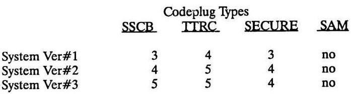
The RSS thinks in terms of System Versions 1, 2, and 3. These are NOT the same as the firmware versions you see when the station powers up. However, there is a relationship between these values, as shown in the table below. Each board in the system has its own firmware version; these are displayed as the system performs self-tests when first powered up, in the same order as shown here. Some combinations are invalid and not supported. The station's firmware must all be in the same System group, i.e. you can't put SSCB Version 5.45 firmware into a station who's TTRC has Version 5.04 firmware. While this seemed obvious to me, apparently not all people (readers or not) understand this. Also note that there are other firmware versions installed that are not listed in the table below; I had a control tray with SSCB 5.45, TTRC 5.30, and Secure 4.23; RSS properly recognized it as a System Version 3 configuration.
| |||||||||||||||||||||||||||||||||||||||||||||||||
You can convert lower System Version code plugs to higher System Version code plugs, but not vice versa. If you started with a System Version 1 or 2 code plug, you could load it into a station with V5.xx firmware by converting it to System Version 3. You do this in the GET/SAVE (F3) menu, Upgrade Code plug Version (F9) item. You can only move upwards with the code plug version, and once done, you cannot go back , unless you put older firmware into the station and manage to get it to accept an older code plug.
The RSS manual has a simpler compatibility table:
You can read the existing code plug from your station and set each of the fields to their default values, then do your own customizations, but it's easier to start with a clean slate and use CONV.DEF or CONV_3.DEF depending on your station's firmware. There are known bugs with firmware versions 3 and 4, so if necessary or possible, try to upgrade your station with the latest version 5 firmware; it's very stable.
IMPORTANT UPDATE: Motorola recommends that you always start with CONV.DEF, and let it automatically upgrade as needed when you write it to the station. RSS will realize the station is a higher version and upgrade the code plug for you. You should also do this if you replace the firmware and are having problems getting the station to accept the new code plug.
If you start with CONV.DEF, a System 1 code plug, it will display SSCB V4, TTRC V4 when you save it to disk. When you read it back, it comes in as SSCB V3, TTRC V4. If you upgrade the code plug to System 2, it will display SSCB V5, TTRC V5 when you save it to disk, which is NOT a valid System 2 code plug. When you read it back, however, it comes in as SSCB V4, TTRC V5, which IS correct for a System 2 code plug. It seems there's a slight bug in RSS.
RSS menu:
The main menu is presented when you first enter RSS and press any key to get past the opening screen. Press GET/SAVE (F3), then either read the station's code plug (F2) or start with an existing (archived) code plug (F3), choose the proper directory, and choose the file, most likely CONV_3.DEF. When it loads, press F10 to get back to the main menu. The rest of this article will dwell on the CHANGE/VIEW Code plug Data (F4) menu item.
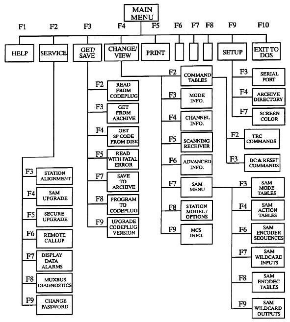
The major functions we'll be dealing with are all under the Change / View (F4) menu item: Mode Information (F3), Channel Information (F4), Scanning Receiver (F5), Advanced Information (F6), and Station Model / Options (F8) functions. I won't cover the command tables (F2), SAM (F7), or MCS (F9) as these aren't used on a repeater with an external controller.
When any field is highlighted, pressing F1 brings up a help screen that provides a description of the setting, its range of values, and the default value. F10 or ESC gets you back to the original screen.
As you experiment with various settings, save the code plug with some kind of unique name, perhaps by using a sequence of numbers, so you can get back to a previous version if necessary. Don't over-write the factory-supplied code plugs; you never know when one could come in handy. It's better to have a bunch of useless code plug files lying around rather than missing the one you need.
Station Settings:
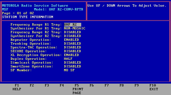
If you're starting with a default code plug, you will have to check and change more settings than might be set in an existing code plug. From the main menu, press Change/View (F4) then Station Model/Options (F8). This brings up the Station Type information screen, page 01 of 02. Begin by setting the "Frequency Range R1 Tray" to the band and range of your station, because when these are changed, all the frequency information on the channel screen is wiped out, and you won't be happy if you have to enter that all over again. Here are your choices:
|
The choice of MOSAIC or Non-MOSAIC for the synthesizer should be automatic (RSS knows the range you just set), but if not, the Non-MOSAIC is used on VHF/UHF where the VCOs operate at the carrier frequency. On 800 and 896 MHz stations, the VCOs operate at one half the carrier frequency and their signals are doubled inside the RF tray. These stations use the MOSAIC synthesizer. If you press HELP (F1), you'll get a nice explanation of the differences. (By the way, MOSAIC stands for "Motorola Oxide Self Aligned Implanted Circuits", whatever that means.)
Repeater Operation really must remain ENABLED, even if you're using the station as a base station. Motorola considers a station where both the receiver and transmitter are active and in use at the same time a "repeater"; a "base" station is one where only the receiver or transmitter is active at any given time, and you wouldn't want the receiver to be on when both the TX and RX frequencies are the same. This field is mis-named; it really controls how the station operates: when ENABLED you get full-duplex; when DISABLED, you get half-duplex, meaning the receiver audio is muted when the transmitter is on. Not at all what you want for repeater use. Even though you would think this field turns the station into a repeater, it does not; to get a true stand-alone repeater using the internal controller, you need to include the "R" in the PTT Qualifier field, described shortly. You just want a full-duplex station since you'll be using an external repeater controller. Everything else can be DISABLED. Note that some fields cannot be changed (trunking, for example) because you're starting with a conventional code plug. If you see that a Trunking, Simulcast, or Spectra TAC field is Enabled, you've started with the wrong code plug. Duplex Operation here applies to the audio path throughout the station, not its ability to operate simplex or duplex. Some stations seem to require this field to be enabled, while others (mine, for example) work fine with it disabled. It probably depends on what signals you're using to interface an external repeater. You may need to play with jumpers on the TTRC to fully configure the station control system. The HELP feature in RSS will give you the details.
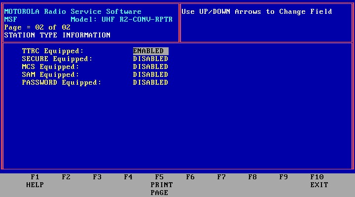
On page 2 there are four very important fields: TTRC Equipped, SECURE Equipped, MCS Equipped, and SAM Equipped. Set these for the hardware present in your system. There are also some jumpers on the SSCB that must be set one way if the hardware is there and set the other way if not. Telling the RSS that you have one of these boards when in fact you do not will cause the system to hang when it tries to communicate with the missing board. Very few stations have Multi-Coded Squelch (MCS) or the Station Access Module (SAM). Make sure these are set to DISABLED except for the hardware you have in the station. If these boards are DISABLED, most of the fields associated with them are not editable, show as DISABLED, and don't show up on the code plug printout. Once you disable the TTRC, you can't enable it later; you would need to start with the particular default code plug and build it up all over again, so be sure you really want to disable it. The same holds true for the SECURE, MCS, and SAM choices. All of the code plug data (and access to their fields) for these options gets deleted.
Entering a password is more trouble than it's worth; add a padlock to your station's cabinet if you're worried about security.
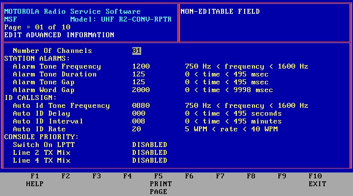
Advanced Settings:
Almost all of these can remain at default values. You may want to change the Auto ID Tone Frequency, set the delay to 0, set the interval to 8 (see note below), and the rate to 20 or less (FCC rules for amateurs require the repeater to ID at least once every 10 minutes at 20WPM or less). Note that these will only have an effect if you're configuring the station as a stand-alone repeater, but it makes sense to set them now as you experiment with the configuration.
And, before you ask, the CW ID deviation is NOT adjustable. It's set at a fixed level by some resistors under the SSCB. It will be sent without PL/DPL unless the repeater hang-time is long enough to keep PL/DPL active during the CW ID.
NOTE: The Auto ID Interval field has a bug. It will accept any value you enter, but it will only retain certain values. For example, it will save 0, 1, 2, 3, 4, 5, 6, 7, and 8, but will change 9 to 000. It will accept 10, but will change 11, 12, 13, and 14 back to 010. Values of 16 thru 19 revert to 015. The RSS manual and Help file say you can enter any integer value between 0 and 495; you can ENTER any value, but it won't necessarily RETAIN that value. It will probably take on the next lower value that's a multiple of 5, 10, or 20 minutes.
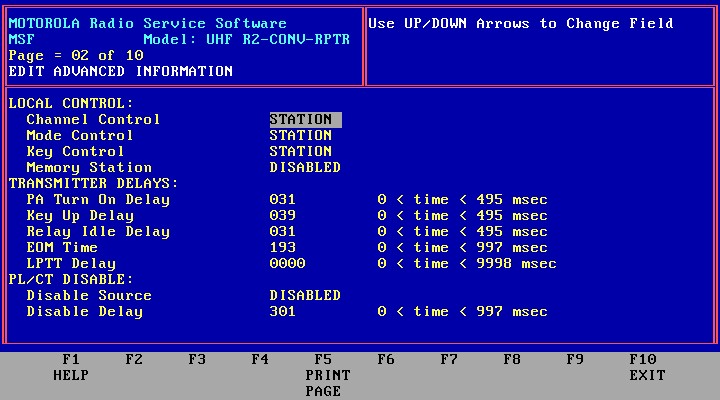
The Local Control settings affect your ability to change the channel, mode, and secure key values from the front panel. Since the station will typically only contain one channel and one mode, this is not too important, but if you set them to REMOTE, you can't change them for testing purposes using the front panel SET/SELECT switch, so set all of these to STATION. Memory Station refers to the station's ability to return to the last mode/channel it was on after power is restored. Since you only have one mode/channel, this field can be set either way.
Leave all the transmitter delays to default values. These were designed to protect the antenna relay and give the PA time to get to full power before being checked and causing an alarm.
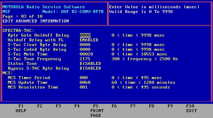
Since you probably aren't running a Spectra TAC system, or have MCS attached, all of these fields can remain at their defaults.
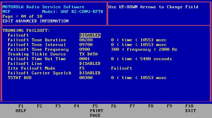
Again, you're making a conventional system, not a trunking system, so all of these remain at their defaults.
If you will be adding your own external controller, most of these also have no meaning and can remain at their default values. If you ever connect a DC or tone remote to the station, you'll want to choose the proper options here. Note that the TTRC is capable of DC or tone control, selectable here and via jumpers on the circuit board.
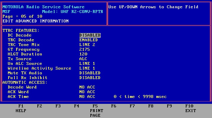
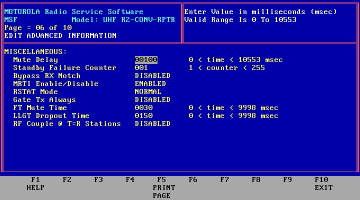
The most important setting on this page is MRTI Enable/Disable. An external controller would connect to the MRTI jack on the SSCB, and you must enable it here in order to use it. The rest of the settings can take default values.
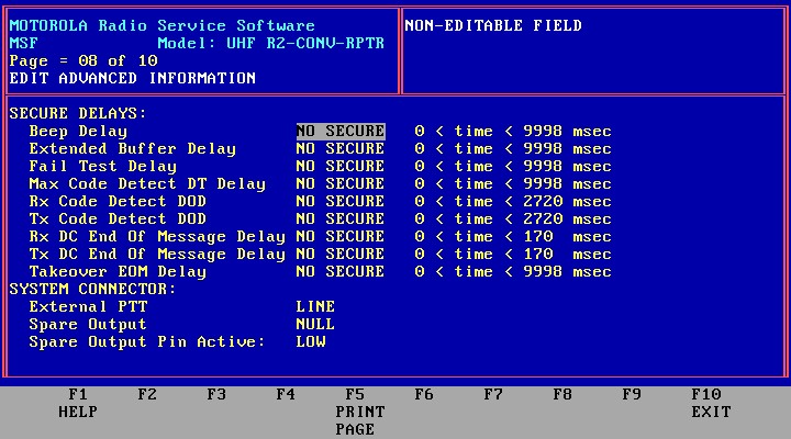
You won't be running secure communications on the amateur band, so there are no secure features to worry about.
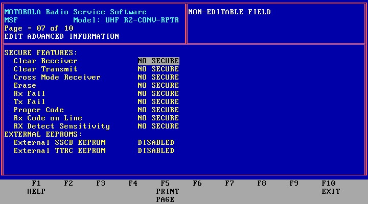
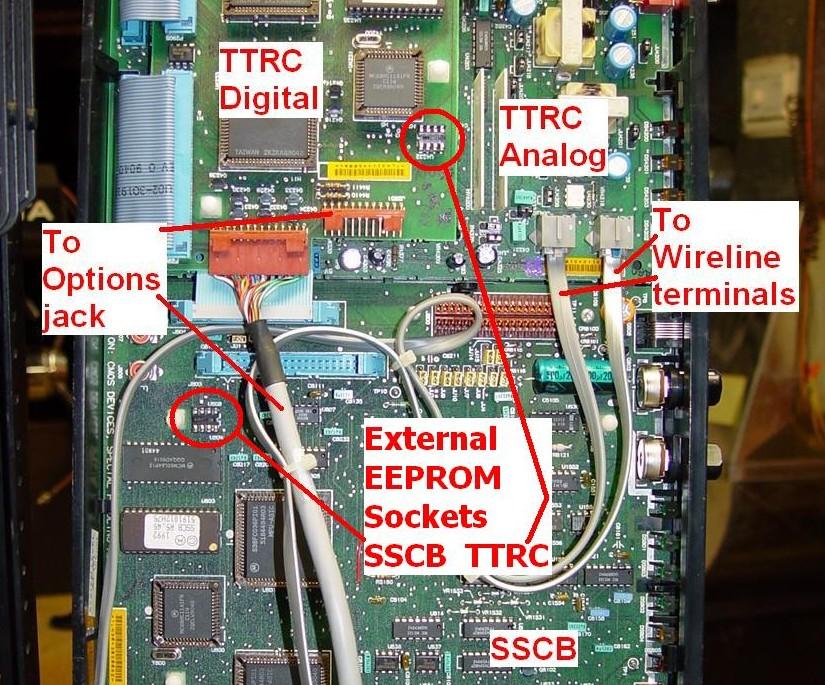
The SSCB and TTRC can each hold an additional serial EEPROM chip for more memory. This would be necessary in some applications such as MCS. Your station most likely does NOT have them. To check, flip the control tray up and look for unoccupied 8-pin IC sockets near the microprocessors on the boards. If they're vacant, you do NOT have the external EEPROM chips. For reference, these parts are listed as 5191015A01 IC CMOS EEPROM 2KX8 SER 24C16, the list price is about $35, they're no longer available from Motorola, but you can buy them (8-pin DIP) for about $0.50 from Mouser or Digikey. I've got a pair and they're marked X24C16PI. The empty sockets are circled in this photo:
Once again, no secure features need be worried about. The System Connector fields could be used for interface purposes; see the MSF Interfacing Signals article in the MSF section of this web site. The RSS manual has quite a lot of information about utilizing this feature.
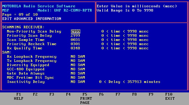
You probably won't have a scanning repeater or a SAM, so all of these just take their default values.
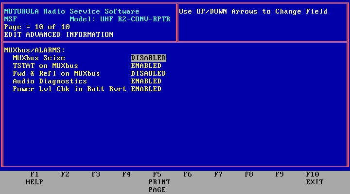
You should enable Audio Diagnostics so the entire station is fully checked when it's plugged in. All of the other settings can remain at their default values.
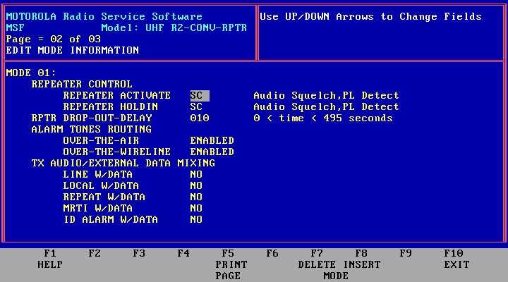
Mode Settings:
Modes and channels are independent. The mode defines things like coded squelch, repeater operation, etc. The channel defines the operating frequency and specifies which mode is linked to it. You can have multiple modes and multiple channels which can be selected from the front panel or a remote control unit. Usually one mode is linked to one channel.
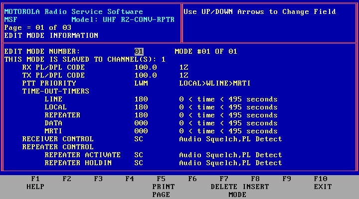
The PTT Priority field accepts several letters, and the priority is arranged left toright. In the example below, the local microphone (L) has the highest priority, followed by the wire line (W), then the MRTI input (M). Each PTT signal gates its own audio input to the transmitter, and a higher priority input should over-ride a lower priority signal. If you want to use the station's internal repeater controller, you need to add "R" to this list, and set some other fields appropriately. You only need "LM" here; I had W in place so I could access the station with a wired remote control.
If you will be using the MRTI jack for your external controller, make sure you set the MRTI Timeout value to 000, otherwise the station will cease transmitting after the number of seconds you set this field to. This little detail pertains to ANY PTT input you might use with an external controller.
The Receiver Control and Repeater Control determine whether coded squelch (C) and/or a carrier signal (S) are required to key the station (Activate) and/or keep it keyed (Hold-in). There are other qualifiers possible. The "SC" combination shown here results in what's known as "AND" squelch; users will need both PL/DPL AND a good signal to operate the repeater.
If you set your station up as a stand-alone repeater for testing, you may want a long hang time. The CW ID is normally sent without transmit PL/DPL, but by using a long hang time, the PL/DPL will still be present during the CW ID, and you'll hear it. Once the transmitter goes off and the station is idle, it will ID once more, without PL/DPL.
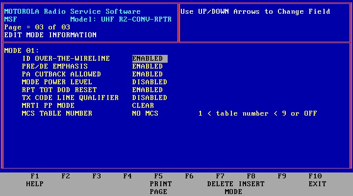
The CAT controllers expect ordinary audio, so Pre/De Emphasis is Enabled. If you use a different controller, adjust this field. West-coast repeaters seem to like using flat audio and let the controller handle Pre/De Emphasis. With the MSF, it's either active for both the transmitter and receiver, or it's turned off. Rpt TOT DOD Reset controls when the internal repeater controller's time-out timer resets: Enabled resets it upon loss of receive carrier; Disabled resets it when the transmitter turns off. You probably want to leave this Enabled, which is the default. MRTI PP Mode only has an effect if you are running secure communications, so it can stay at its default value of RX SLAVED.
Channel Settings:
Here is where you set the operating frequency of the station. If you'll be entering frequencies outside the normal range for the station, the RSS will complain but you can force your values in. Don't let RSS trick you into choosing appropriate frequencies for you; enter them all yourself, especially for the 900 MHz amateur band. The idle frequency is where the transmit VCO will sit when the station is not transmitting. Usually the choice is automatic, and it will be the transmitting frequency if you only have one channel, but you may want to specify a frequency slightly removed from the transmit frequency so you don't hear the signal from the VCO when the station is idle. I'd recommend 50-100 kHz above or below your frequency, depending on where there is less chance for interference to other nearby systems. If you leave this on your transmit frequency, you will hear the VCO signal on any nearby receiver - such as your hand-held radio - when you walk into the equipment room.
The frequencies on 800 and 896 MHz stations must be evenly divisible by 12.5 kHz. On the lower bands they must be evenly divisible by 5.0 or 6.25 kHz. RSS will accept anything but the station won't be on the programmed frequency if you violate the rules.
Enter your Call Sign. There's room for 8 characters, so you can add /R to it. To eliminate the CW ID entirely, fill this field in with blanks.
You also get to choose the default Mode number, although with only one mode, there's not much to choose from. The PL/DPL codes are taken from the first page of the Mode screen.
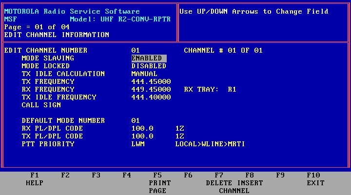
The remaining three screens of channel information are actually the three Mode screens. You can change that data from either location.
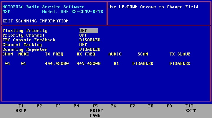
Scan Settings:
Just keep the scanning disabled. You don't need or want it for a repeater, and in fact you need at least two channels to permit scanning.
Finalizing the Configuration:
You've actually filled in all the important settings. At the main menu, choose GET/SAVE (F3), Save to archive file (F7), choose the archive directory, and give your code plug a unique name. Press <ENTER> to save it, then Write it to the station (F8). This will take a couple of minutes, and happens in two phases. The first phase sends the SSCB, TTRC, and SECURE data (depending on which boards are present) to the station, where it's held in memory. You'll see a progress bar jump in steps until it gets to 100%. This data is then written to the code plug space in the individual boards in the same order, and another progress bar tells you when it's finished. At the completion of this operation, the station will reset, go through its self-tests, and it should come up with "11" on the display. At this point, the station is ready for operation. If you've moved the frequencies significantly (more than several MHz), you may have to tune the VCOs to get them to lock, and/or tune the mixer and front end coils.
Unfortunately, the default code plug will set some EEPots to zero (such as deviation and repeater gain) while others may assume a random value. You can adjust the EEPots via the Service (F2) Station Alignments (F3) menu. Raise the Max Deviation Level (EEPot 4) to 80 (that will at least get you in the ballpark; you should set it properly by following the procedure in the alignment section of the service or installation manual). Set the Repeater Squelch Level (EEPot 2), Receiver Squelch Level (Eepot 3), and RX Level (EEPot 5) to 50 just to get you going. These should also be set after you get your final repeater configuration going.
After you finish setting the EEPots, you should read the station's code plug and save it on your computer as the same file you just sent to it. This will bring in the EEPot values as they are now part of the code plug data. Continue to refine your settings by working with the latest good code plug; there's no need to go back to CONV_3.DEF to start fresh.
You can access the various status bits, that are displayed on the digital metering panel, through the Service (F2), MUXBus Diagnostics (F8) menu, but you can't change the EEPots at the same time, as they're on a different screen. I don't know which is easier: monitoring the MUXBus with a DMP and changing the EEPots via RSS, or monitoring the MUXBus via RSS and changing the EEPots via the Set/Select switch on the SSCB. The procedure for accessing the EEPots via the front panel is documented in the Instruction manual for the station.
Code plug Printout:
Here's what comes out when you press PRINT (F5) from the main menu. These have been reduced in size for ease of viewing. Click on any page to get the full-size image:
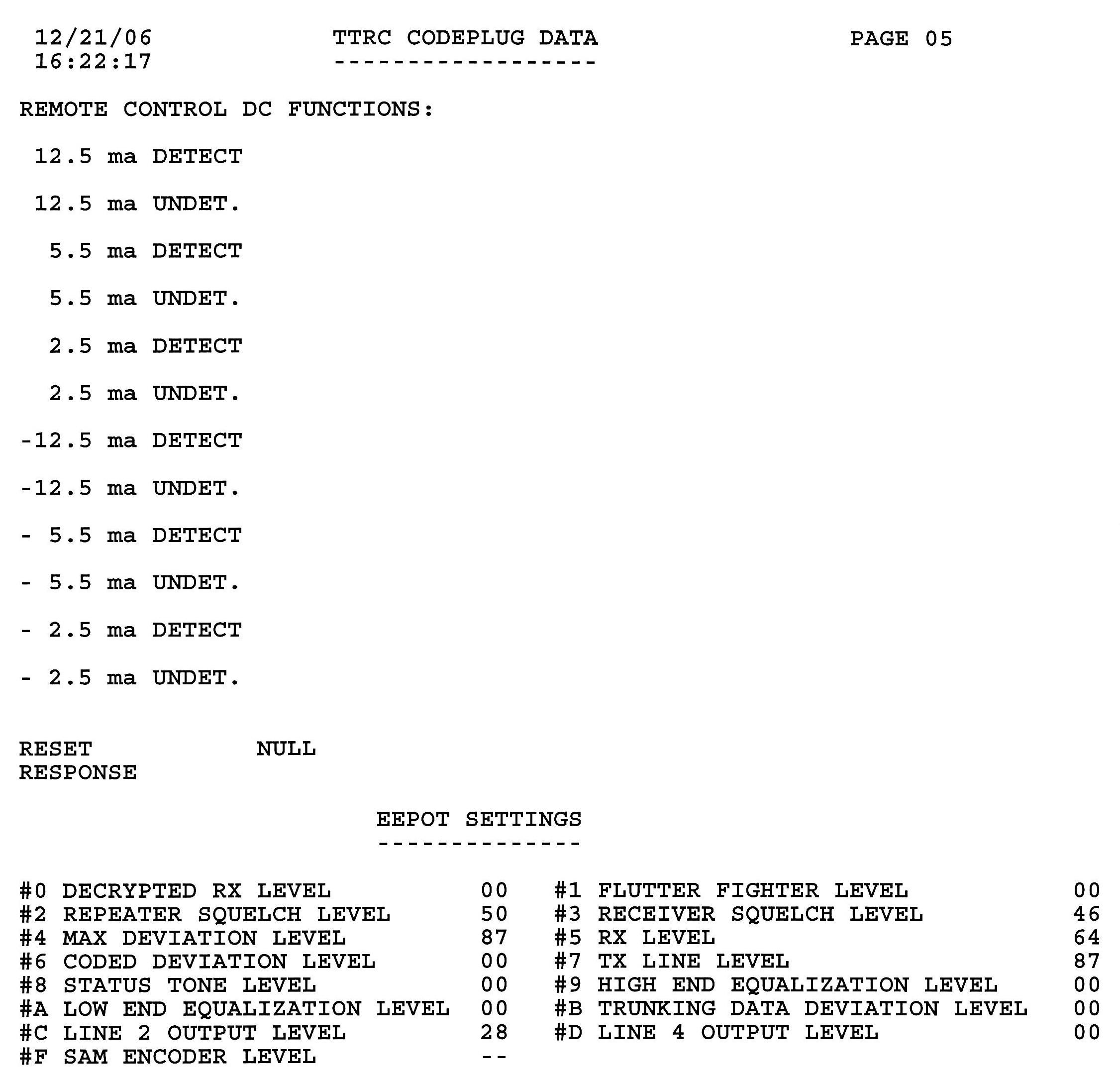
I subsequently scanned these pages, tabularized the data, and added some information to the fields. Before looking further, these notes are important:
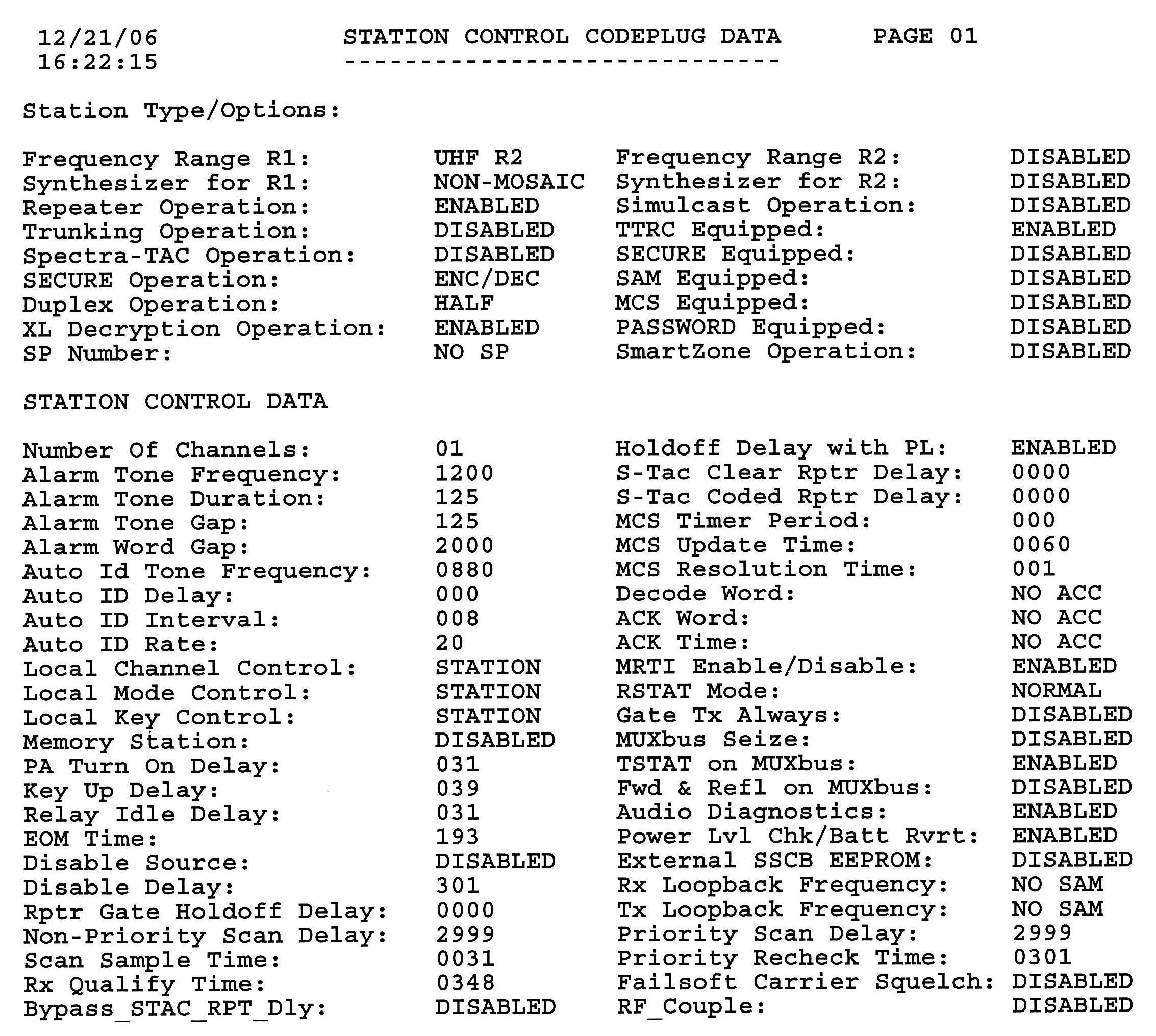
STATION CONTROL CODE PLUG DATA - PAGE 01
Station Type/Options:
Frequency Range R1: UHF R2
S1 default
Synthesizer for R1: NON-MOSAIC
S1 default
Repeater Operation: ENABLED
S1 default
Trunking Operation: DISABLED
S1 non-edit
Spectra TAC Operation: DISABLED
S1 non-edit
SECURE Operation: ENC/DEC
S1 TRANSPRNT
Duplex Operation: HALF
S1 default
XL Decryption Operation: ENABLED
S1 default
SP Number: NO SP
S1 non-edit
(the right-half of this area is shown below)
Frequency Range R2: DISABLED
S1 default
Synthesizer for R2: DISABLED
S1 default
Simulcast Operation: DISABLED
S1 non-edit
TTRC Equipped: ENABLED
S2 default
SECURE Equipped: DISABLED
S2 ENABLED
SAM Equipped: DISABLED
S2 default
MCS Equipped: DISABLED
S2 default
PASSWORD Equipped: DISABLED
S2 default
SmartZone Operation: DISABLED
S1 default
STATION CONTROL DATA
Number Of Channels: 01
A1 non-edit
Alarm Tone Frequency: 1200
A1 default
Alarm Tone Duration: 125
A1 default
Alarm Tone Gap: 125
A1 default
Alarm Word Gap: 2000
A1 default
Auto Id Tone Frequency: 0880
A1 800
Auto ID Delay: 000
A1 005
Auto ID Interval: 008
A1 015
Auto ID Rate: 20
A1 default
Local Channel Control: STATION
A2 REMOTE
Local Mode Control: STATION
A2 default
Local Key Control: STATION
A2 REMOTE
Memory Station: DISABLED
A2 ENABLED
PA Turn On Delay: 031
A2 default
Key Up Delay: 039
A2 default
Relay Idle Delay: 031
A2 default
EOM Time: 193
A2 default
Disable Source: DISABLED
A2 MUTE REQ
Disable Delay: 301
A2 703
Rptr Gate Holdoff Delay: 0000
A3 default
Non-Priority Scan Delay: 2999
A9 default
Scan Sample Time: 0031
A9 default
Rx Qualify Time: 0348
A9 default
Bypass_STAC_RPT_Dly: DISABLED
A3 default
(the right-half of this area is shown below)
Holdoff Delay with PL: ENABLED
A3 default
S-Tac Clear Rptr Delay: 0000
A3 default
S-Tac Coded Rptr Delay: 0000
A3 default
MCS Timer Period: 000
A3 default
MCS Update Time: 0060
A3 default
MCS Resolution Time: 001
A3 default
Decode Word: NO ACC
A5 default
ACK Word: NO ACC
A5 default
ACK Time: NO ACC
A5 default
MRTI Enable/Disable: ENABLED
A6 DISABLED
RSTAT Mode: NORMAL
A6 default
Gate Tx Always: DISABLED
A6 default
MUXbus Seize: DISABLED
A10 default
TSTAT on MUXbus: ENABLED
A10 non-edit
Fwd & Refl on MUXbus: DISABLED
A10 default
Audio Diagnostics: ENABLED
A10 DISABLED
Power Lvl Chk/Batt Rvrt: ENABLED
A10 default
External SSCB EEPROM: DISABLED
A7 default
Rx Loopback Frequency: NO SAM
A9 default
Tx Loopback Frequency: NO SAM
A9 default
Priority Scan Delay: 2999
A9 default
Priority Recheck Time: 0301
A9 default
Failsoft Carrier Squelch: DISABLED
A4 default
RF_Couple: DISABLED
A6 default
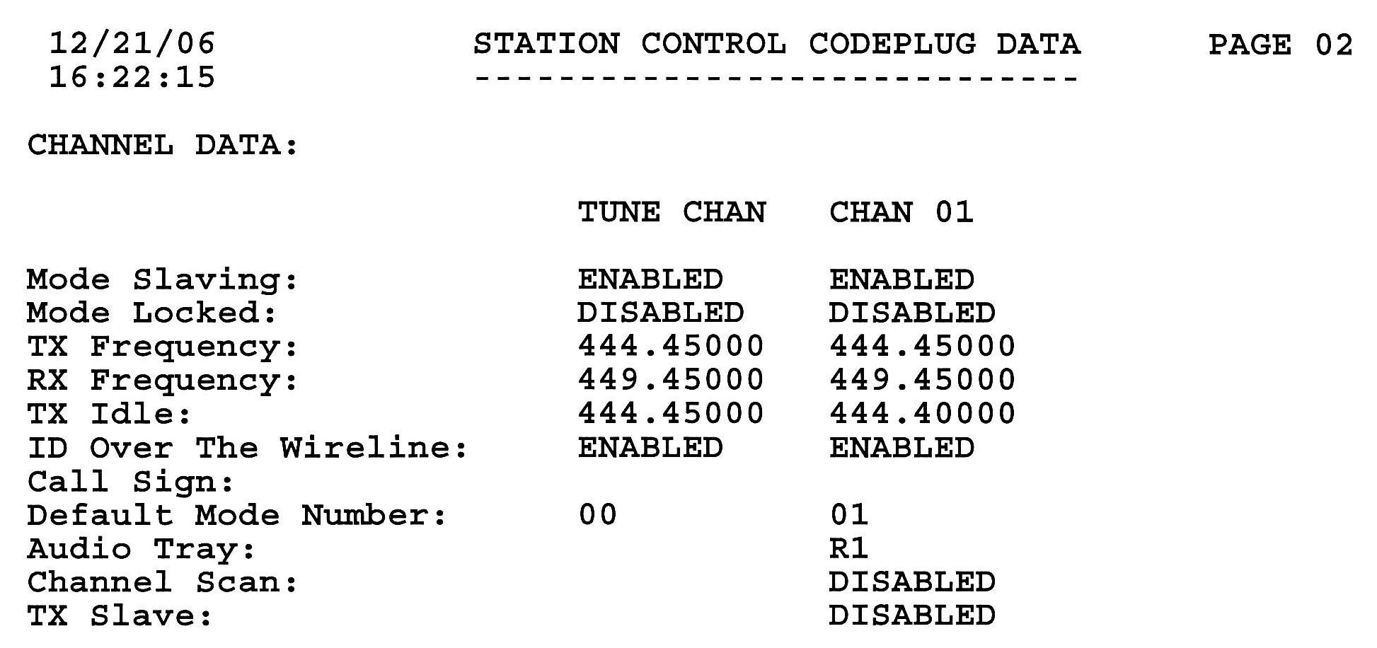
STATION CONTROL CODE PLUG DATA - PAGE 02
CHANNEL DATA:
TUNE CHAN CHAN 01
Mode Slaving: ENABLED ENABLED
C1 default
Mode Locked: DISABLED DISABLED
C1 default
TX Frequency: 444.45000 444.45000
C1 user
RX Frequency: 449.45000 449.45000
C1 user
TX Idle: 444.45000 444.40000
C1 user
ID Over The Wireline: ENABLED ENABLED
M3 DISABLED
Call Sign:
C1 user
Default Mode Number: 00
01 C1 user
Audio Tray: R1
SC default
Channel Scan: DISABLED
SC default
TX Slave: DISABLED
SC default
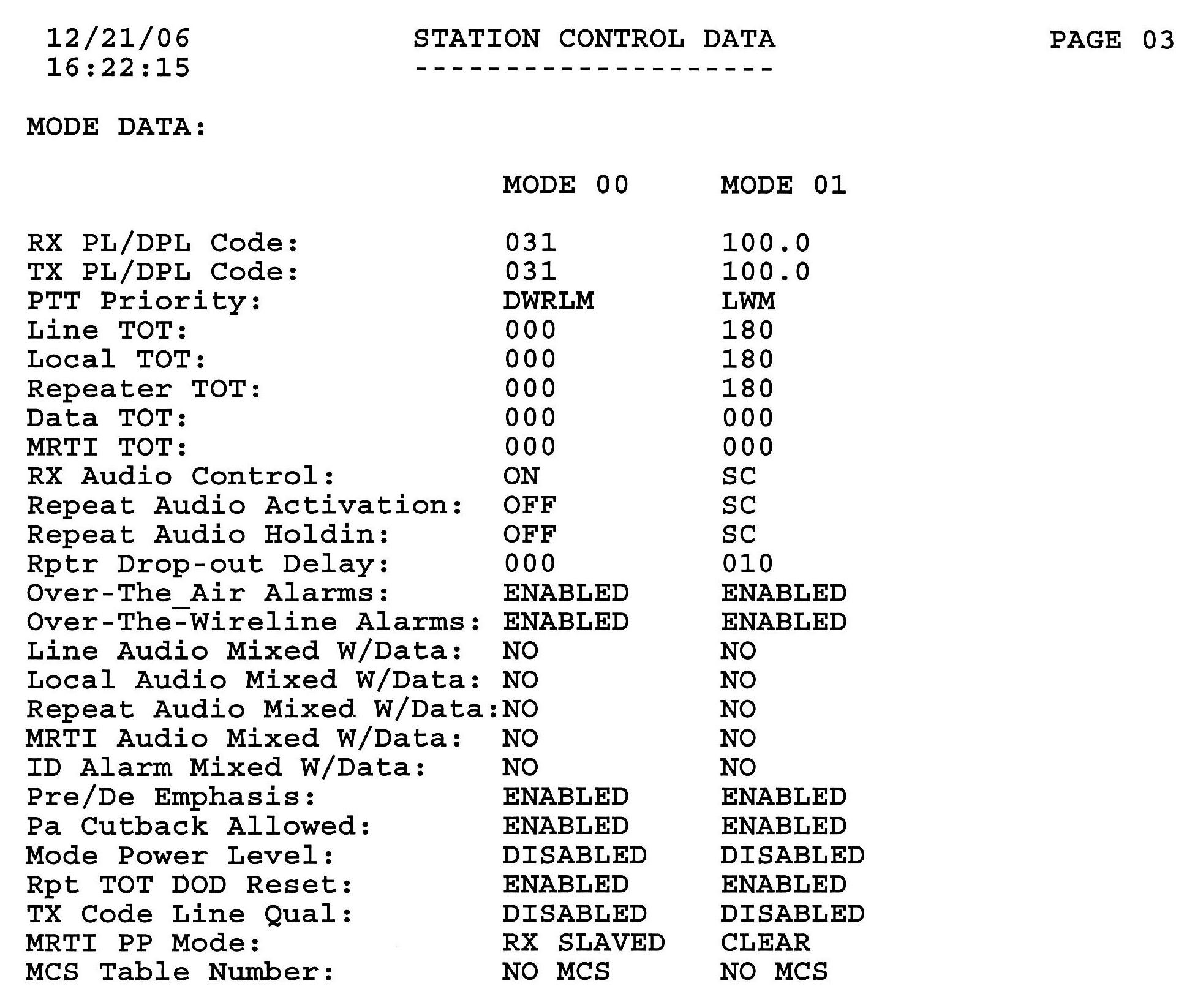
STATION CONTROL DATA - PAGE 03
MODE DATA:
MODE 00 MODE 01
RX PL/DPL Code: 031 100.0
M1 CSQ
TX PL/DPL Code: 031 100.0
M1 CSQ
PTT Priority: DWRLM LWM
M1 DWRLM
Line TOT: 000 180
M1 120
Local TOT: 000 180
M1 000
Repeater TOT: 000 180
M1 060
Data TOT: 000 000
M1 default
MRTI TOT: 000 000
M1 default
RX Audio Control: ON
SC M1 S
Repeat Audio Activation: OFF
SC M2 S
Repeat Audio Holdin: OFF SC
M2 S
Rptr Drop-out Delay: 000 010
M2 002
Over-The-Air Alarms: ENABLED ENABLED
M2 default
Over-The-Wireline Alarms: ENABLED ENABLED
M2 default
Line Audio Mixed W/Data: NO NO
M2 default
Local Audio Mixed W/Data: NO NO
M2 default
Repeat Audio Mixed W/Data: NO NO
M2 default
MRTI Audio Mixed W/Data: NO NO
M2 default
ID Alarm Mixed W/Data: NO NO
M2 default
Pre/De Emphasis: ENABLED ENABLED
M3 default
Pa Cutback Allowed: ENABLED ENABLED
M3 default
Mode Power Level: DISABLED DISABLED
M3 default
Rpt TOT DOD Reset: ENABLED ENABLED
M3 default
TX Code Line Qual: DIABLED DISABLED
M3 default
MRTI PP Mode: RX SLAVE CLEAR
M3 default
MCS Table Number: NO MCS NO MCS
M3 non-edit
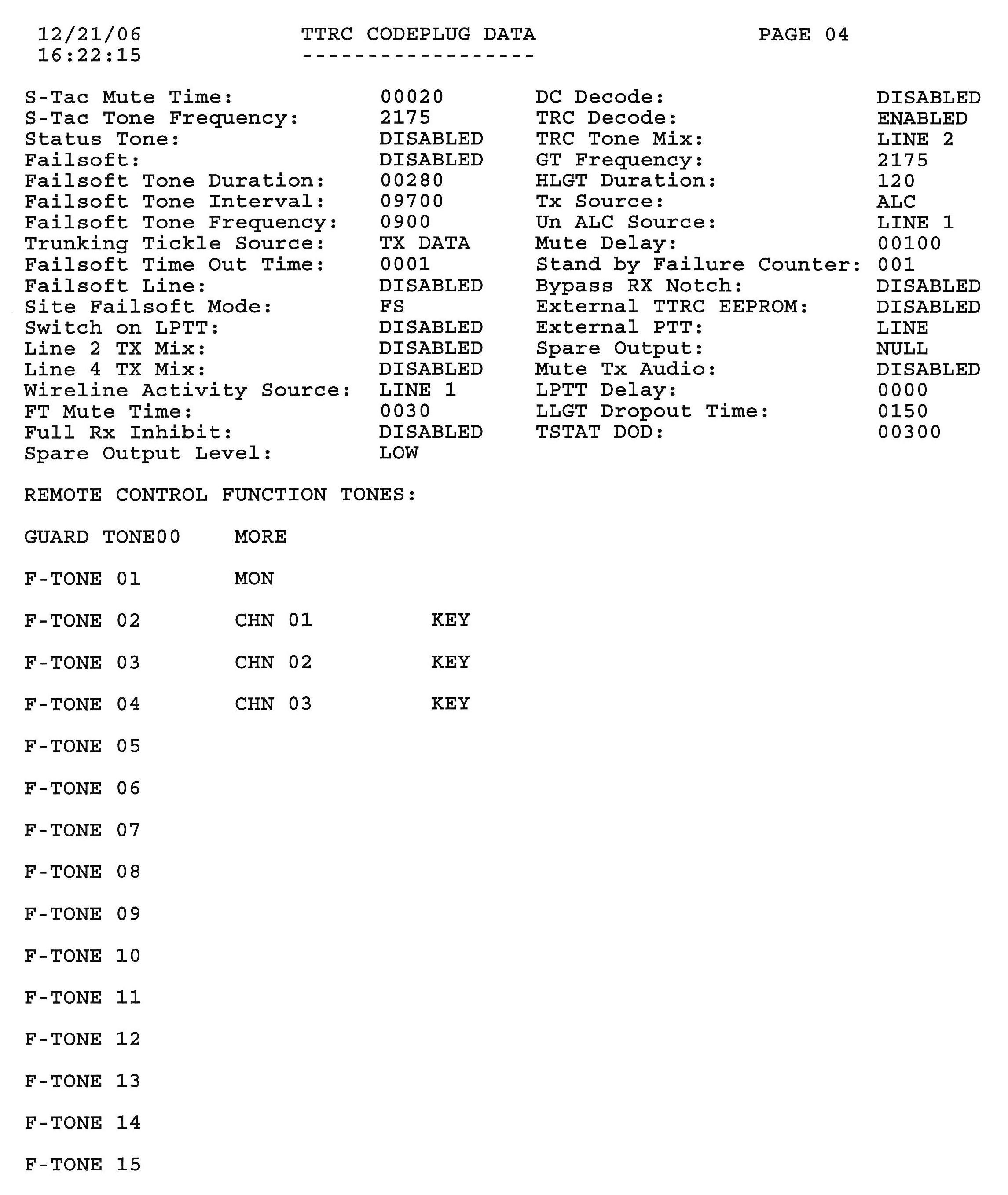
TTRC CODE PLUG DATA - PAGE 04
S-Tac Mute Time: 00020
A3 default
S-Tac Tone Frequency: 2175
A3 default
Status Tone: DISABLED
A3 default
Failsoft: DISABLED
A4 default
Failsoft Tone Duration: 00280
A4 default
Failsoft Tone Interval: 09700
A4 default
Failsoft Tone Frequency: 0900
A4 default
Trunking Tickle Source: TX DATA
A4 default
Failsoft Time Out Time: 0001
A4 default
Failsoft Line: DISABLED
A4 default
Site Failsoft Mode: FS
A4 default
Switch on LPTT: DISABLED
A1 default
Line 2 TX Mix: DISABLED
A1 default
Line 4 TX Mix: DISABLED
A1 default
Wireline Activity Source: LINE 1
A5 default
FT Mute Time: 0030
A6 default
Full Rx Inhibit: DISABLED
A5 default
Spare Output Level: LOW
A8 default
(the right-half of this area is shown below)
DC Decode: DISABLED
A5 default
TRC Decode: ENABLED
A5 default
TRC Tone Mix: LINE 2
A5 default
GT Frequency: 2175
A5 default
HLGT Duration: 120
A5 default
Tx Source: ALC
A5 default
Un ALC Source: LINE 1
A5 default
Mute Delay: 00100
A6 default
Stand by Failure Counter: 001
A6 default
Bypass RX Notch: DISABLED
A6 default
External TTRC EEPROM: DISABLED
A7 default
External PTT: LINE
A8 default
Spare Output: NULL
A8 default
Mute Tx Audio: DISABLED
A5 default
LPTT Delay: 0000
A2 default
LLGT Dropout Time: 0150
A6 default
TSTAT DOD: 00300
A4 default
Changes for a Stand-Alone Repeater:
The MSF5000 can be configured as a stand-alone repeater, provided you have dealt with separating the transmitter's RF signal from the receiver. A base station would have an antenna relay; this needs to be bypassed and disconnected so the receiver always has an antenna connection and the transmitter goes to its own separate antenna jack. I have used the same screen/page naming convention as in the tables above.
This gives you a hang-time of 10 seconds, the CW ID will fire one second after loss of input carrier, and the CW ID will happen every eight minutes. The local and repeater timeouts are set for three minutes. The MRTI time-out has been set to zero so it's ready for an external controller. The local microphone has priority, followed by the MRTI input, and finally the repeater.
Note that some of these are not really necessary for repeater operation, but are just recommended settings that will minimize the changes you need to undo later. When you get around to making the station operate with an external controller, you only have to change the following fields:
Acknowledgements and Credits:
The latest Motorola MSF5000 Digital Field Programming Software product RVN-4077 version R05.21 and manual (6881125E68-F, 1/27/95) were used in the preparation of this article.
Screens shots were taken using a program called "Screen Thief" for DOS, which produced a .BMP file for each screen. These were subsequently converted to .JPG files.
Contact Information:
The author can be contacted at: his-callsign [ at ] comcast [ dot ] net.
Back to the top of the page
Up one level (MSF index)
Up two levels (Motorola index)
Back to Home
This page originally posted on Monday 08-Jan-2007
Photographs, article text, artistic layout, and hand-coded HTML © Copyright 2007 by Robert W. Meister WA1MIK.
This web page, this web site, the information presented in and on its pages and in these modifications and conversions is © Copyrighted 1995 and (date of last update) by Kevin Custer W3KKC and multiple originating authors. All Rights Reserved, including that of paper and web publication elsewhere.