Back to Home
MASTR III VHF Station for
Amateur Radio Frequencies
By Matt Krick K3MK
FluX Research

|
Up one level (GE Index) Back to Home |
Modifying the GE/MACOM MASTR III VHF Station for Amateur Radio Frequencies By Matt Krick K3MK FluX Research |
|
This article provides conversion instructions for radio model # GE/MACOM MASTR III Group 2 (150.8-174 MHz) Repeater or Base, Combination Number SXS, to allow it to perform adequately in the 144-148 MHz range.
Warning:
Please be aware that this document is currently a work in progress, which may contain several omissions and typographical errors. Continue reading at your own risk.
Background:
The following LBIs may be helpful:
LBI38540D MASTR IIe / III UTILITY PROGRAM
LBI38636C MASTR III CONVENIONAL BASE STATION Installation Manual
LBI38550A
MASTR II / III SITE EQUIPMENT POWER SUPPLY
LBI38625A
MASTR III EMERGENCY POWER OPTIONS
LBI38754A MASTR III RF PACKAGE VHF GROUP 2 (150.8-174 MHz)
LBI38637K
MASTR III T/R SHELF 19D902839G1
LBI38640B
VHF TRANSMITTER SYNTHESIZER MODULE 19D902780G1
LBI38641B
VHF RECEIVER SYNTHESIZER MODULE 19D902781G1, G2
LBI39642B
VHF RECEIVER FRONT END MODULE 19D902782G1, G2
LBI38643B
25kHz RECEIVER IF MODULE 19D902783G1
LBI39123
12.5/25kHz RECEIVER IF MODULE 19D902783G7
LBI38764C
EARLY SYSTEM MODULE 19D902590G1, G3, G5
LBI39176
LATE SYSTEM MODULE 19D902590G6 & G7
LBI38752B
SWITCHING POWER SUPPLY MODULE 19D902589G2, 19D902961
LBI38531A 136-174 MHz, 110 WATT POWER AMPLIFIER 19D902797G1, 19A70532P1, 344A3221P1, 19A705532P2, 19D902794G1, 19D902794, 19D902793
Phase 0 - Preparations:
Make sure the station to be converted is in good working order on its original frequencies before attempting conversion to Amateur Radio use. Note that a Fault light on the Receiver Synthesizer Module may be the result of a missing External Reference Source. Verify in programming software and set source to internal if that is the case.
About 90% of the screws in the MASTR III T/R Frame are Torx T-15. The remaining hardware is T-6, T-8, T-10 or Phillips #2.
To tune the Receiver Front End module properly, I recommend using a service monitor with a spectrum analyzer (HP-8920 series, IFR-1600S or similar). It is possible to use a signal generator and a frequency selective RF voltmeter, or a service monitor with simultaneous generate and receive, but these are not as easy as you can't see where the peaks and dips are.
You will need a copy of TQ-3353 MASTR-IIe, III Programming Software (M2E.BAT, M3.BAT). This should also come with TQ-0619 (MASTRUTL.BAT).
Full Modification requires a great deal of surface mount soldering. You will need a quality soldering iron. I use a Weller with an 800 degree tip 'R', along with fine diameter solder, 0.015 inch, and fine tweezers.
You will also need thicker gauge solder and a brute force tip for modification of the tuning slugs. I recommend 2% silver solder for use here.
Phase 1 - Operating Frequency Reprogramming:
Please Refer to LBI38540D
Connection to the repeater is done with a straight through DE-9 RS-232 cable. Connect either to the Data Port on the front of the repeater or the DE-9 connection on the rear of the interface board.
MASTRUTL.BAT is used as a utility to verify station operation and to set potentiometer values.
You will use this application to set the repeat audio levels and transmitter power output. It can also help diagnose the repeater to a degree with the ability to convey that one or more modules are malfunctioning.
M2E.BAT and M3.BAT are designed to change the station operating parameters, such as CTCSS tones and hang times, and in the case of the MASTR III, the operating frequencies.
It is important that the software be in MASTR III mode. Programming the repeater with the software in M2e mode may inadvertently brick the System Module requiring replacement. Start the software with M3.BAT. Be sure the screen looks like above with the 'MASTR III Control Shelf Programming' at the top.
This software has some compatibility issues, as it is an older DOS based program. A PIII tablet with a USB to RS-232 adapter and WinXP would not program, but a PII laptop with a hardware based serial port and WinXP would.
Read and save the current configuration. Use F6. Read it twice, once as a backup then the other as the file you will be editing.
Once that is done highlight the file you will be editing and hit F2. Edit the data to your new operating parameters. Use F9 over any field to get a description of what it adjusts. For some reason 'space' is not an allowed character when programming the Morse Code ID, so don't pull your hair out. Once done save the data by pressing F10 and then F1 and confirm the over-write.
Send programming data to the repeater by pressing F5 and selecting the file you just edited.
The Fault LEDs on the Transmitter and Receiver synthesizer modules should now be lit as the PLLs are no longer able to lock. There may be a slight flicker on the LEDs as the System Module will be attempting to reset the synthesizers until the fault clears.
Phase 2 - VHF Transmitter Synthesizer Module:
Please Refer to LBI38640B
Remove the Transmitter Synthesizer Module from the T/R frame. Using a small straight jeweler's screwdriver or 'greenie' and a flashlight, adjust the DIP switches through the access hole in the cover of the module to the following configuration:
Position 1: Open
Position 2: Closed
Position 3: Open
Position 4: Open
Leave positions 5 and 6 as is.
Replace the card back into the T/R frame. Put the station into transmit mode and notice that the Fault LED should no longer be lit.
It is not necessary to remove the cover of the module for adjustment, but doing so allows easier access.
With a spectrum analyzer verify the output of the module to be approximately 15 mW (11.5 dBm).
Phase 3 - VHF Receiver Synthesizer Module:
Please Refer to LBI38641B
Please note that the Group 1 (136 - 151 MHz) Synthesizer generates high side Local Oscillator injection where as the Group 2 (150.8 - 174 MHz) generates low side. The output frequency of the Receiver Synthesizer Module will be: Receive Frequency + 21.4 MHz, i.e. 146.04 MHz + 21.4 MHz = 167.44 MHz.
Remove the Receiver Synthesizer Module from the T/R frame and remove the top cover. Flip the card over and remove the 6 screws that hold the RF shielding sub frame around the VCO section.
If you want full Group 1 conversion, replace the Group 2 components to the G1 specifications as found in the manual. A few component changes are all that is necessary for Amateur Radio service.
Remove C2. Replace C1 with a 6pF NP0 0805 Capacitor or equivalent. Keep the original C1 and C2 should replacement be necessary. Use a piece of Scotch tape and a Sharpie to label each one. Replace the VCO RF shielding but not the module shield.
You will now have to remove the Receiver Front End Module and IF Module from the T/R frame so you can access the tuning adjustments of the VCO.
Tuning can be done two ways:
Using a quality frequency counter on LO Output and adjust the trimmer on Y1 until the desired LO frequency reads true. This method offers greater precision than looking at the 12.8 MHz Reference Output.
Once tuned, remove the module from the frame again and replace RF shield. Insert the module back into frame. Verify VCO lock by Fault LED being extinguished. Power cycle the repeater leaving it off for one minute and check that the PLL lock took. The fault LED should stay lit for approximately five seconds but then go out.
I find the Group 2 Low Pass Filter on the output is better designed than the Group 1, offering 3dB more rejection of the second harmonic so no changes were made here.
With a spectrum analyzer verify the output of the module to be approximately 1 mW (0 dBm), Also verify that the harmonics are at least 29dB below the carrier level.
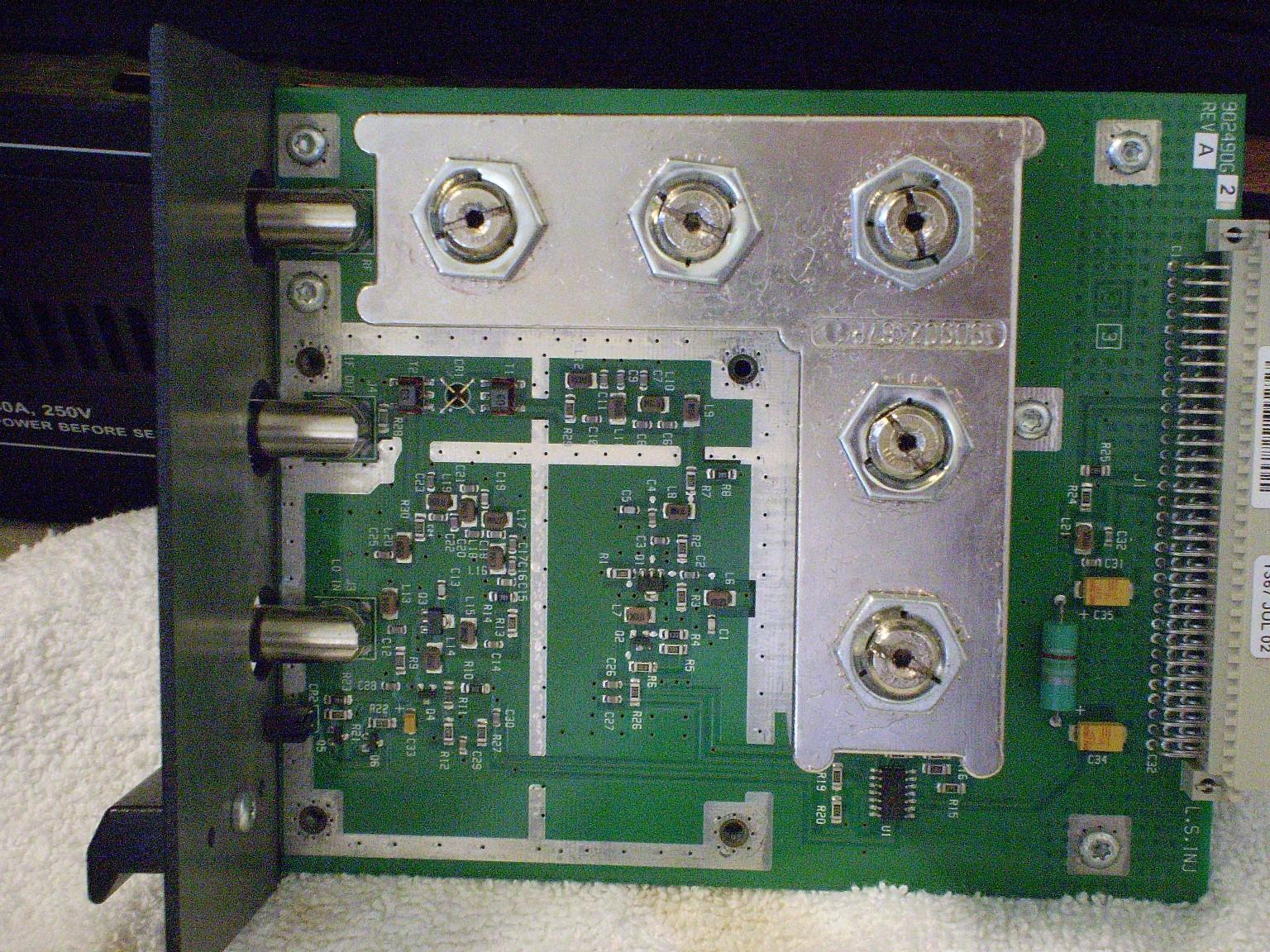
Phase 4 - VHF Receiver Front End Module:
Please Refer to LBI38642B
To modify the tuning slugs you will need 5 brass 8-32 Acorn nuts. These run about $2 for packs of 4. Verify they do not overlap the tuning slugs before purchase. You may need to use 6-32 nuts instead if this is the case. You will also need some kind of non-flammable and non-heat sinking support structure, such as a glass ashtray or ceramic tile.
Remove the tuning slugs from the helical coil assembly. Remove the retaining nuts and set them aside.
One at a time, modify the slugs. Pre-tin the bottom of the slug using the silver solder. It just needs a light coat. Do not spill any on to the threads.
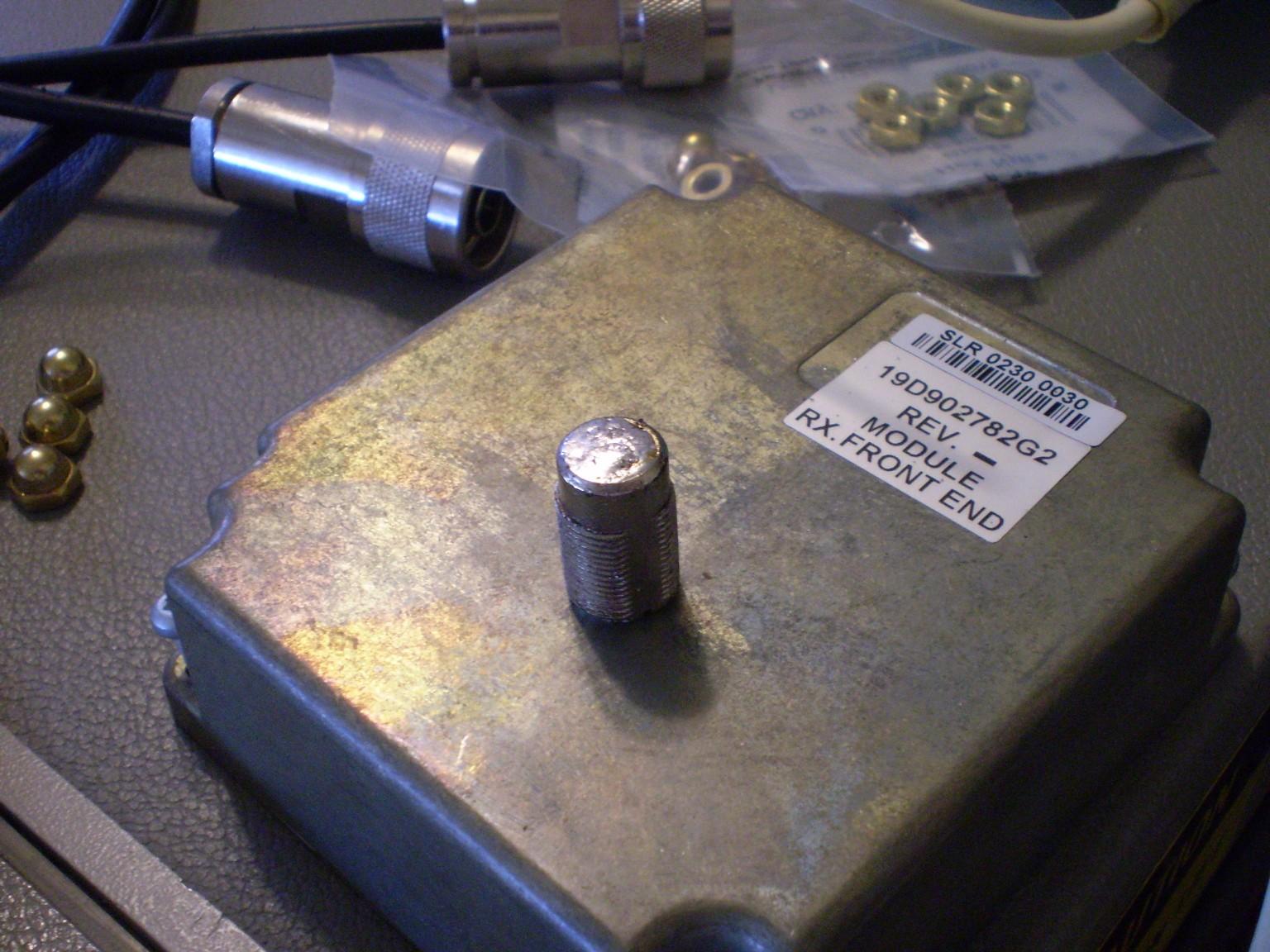
While holding the acorn nut with needle nose pliers, tin the bottom with the solder. Put an extra dab in the center of the nut to help with adherence later. Touch the iron to the slug, the nut to the iron. Heat both the bottom of the slug and the nut to the point where fumes just start to appear, Remove the heat and attach the nut to the bottom of the slug. Check the centering while the solder is still melted.
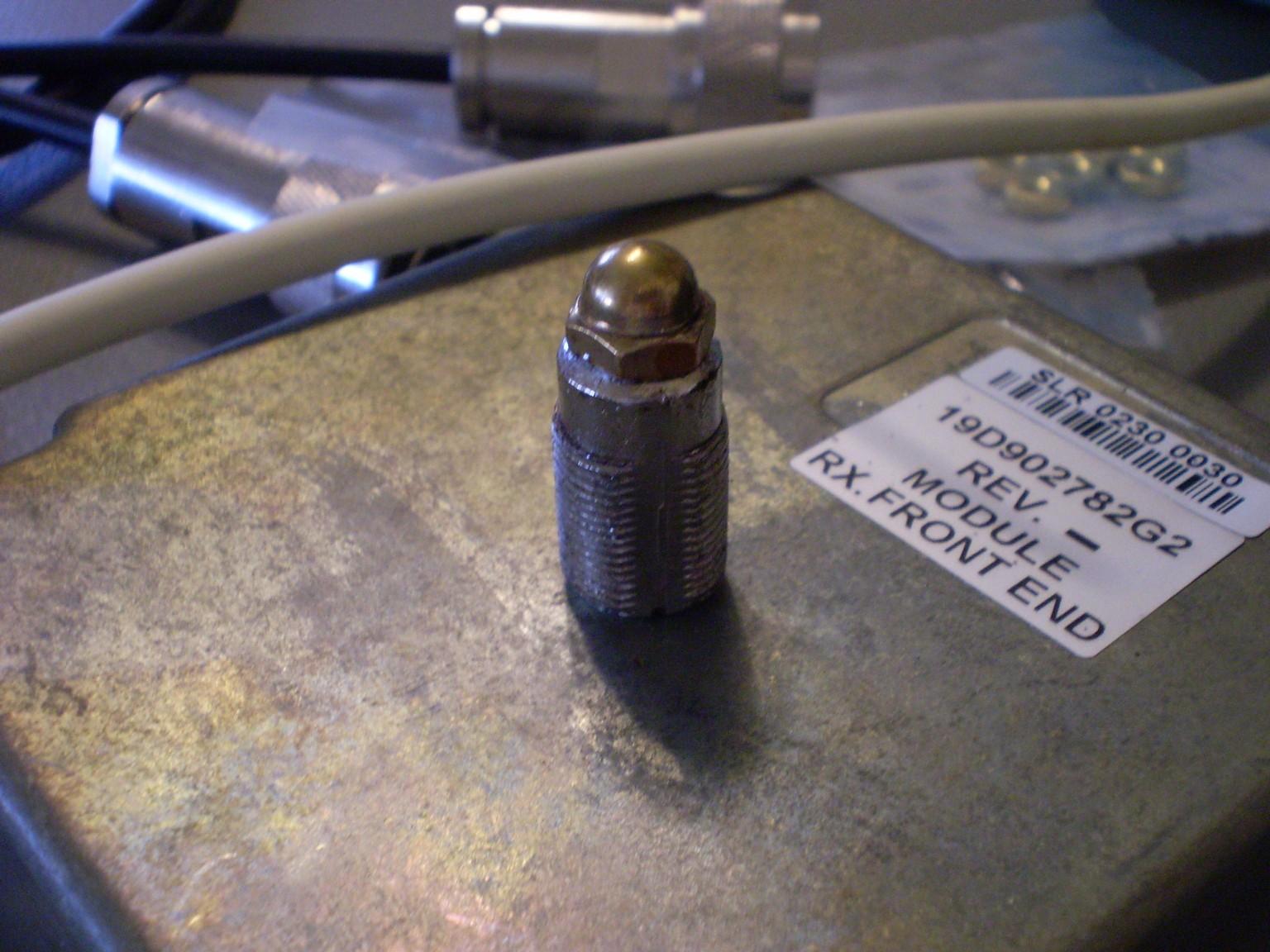
You could also use a small butane pencil torch. Tin the nut and slug as above and then place the nut on the slug cold. Heat the slug with the torch, circling the assembly evenly. Be careful not to discolor the metal.
Wait approx 30 seconds for the solder to solidify and with the pliers place the assembly on a sponge to finish cooling. Clean off the solder flux with a rag and some denatured alcohol. Isopropyl alcohol works if that is all you have. The cleaner it is, the better.
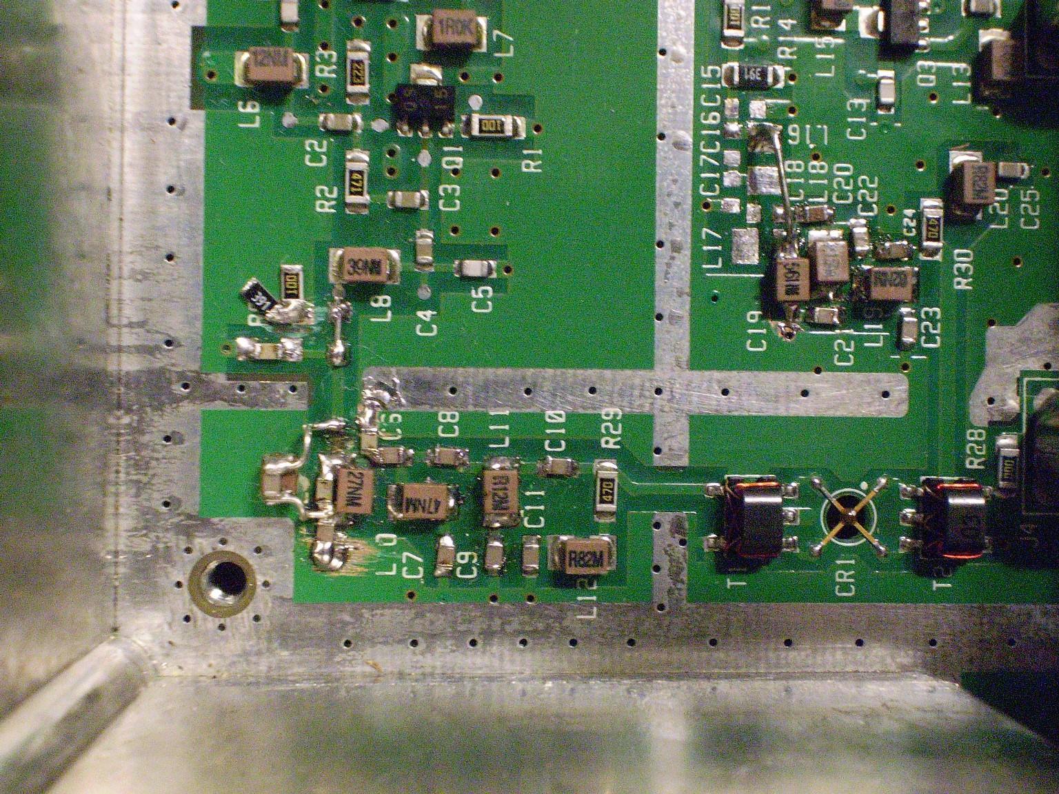
When done you should have something that looks like this:
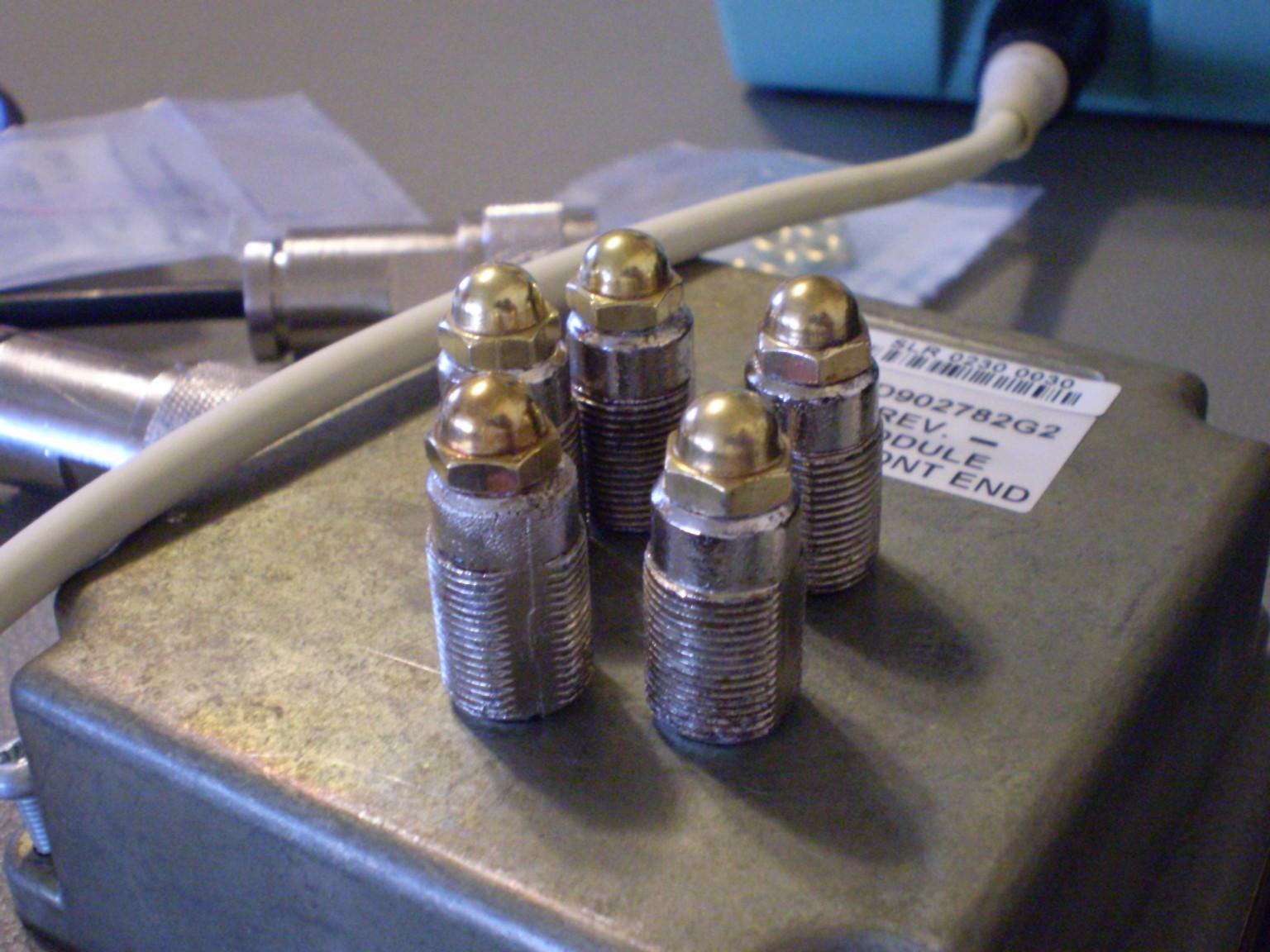
At this point you should be able to make the receiver tune to at least -110dBm (0.7uV) for 12dB SINAD, -113dBm (0.5uV) typical. Skip ahead to tuning if this is good enough for you, otherwise continue down this surface mount path of doom!
The stock image rejection filter attenuates 3dB at 145 MHz; not too good for amateur range applications. The boards are too different to simply change the component values. The G1 board uses a low pass image filter instead of a high pass one. Of course we could just remove the filters but that would offer no image rejection and selectivity would take a hit.
It was decided to swap the filter sections on the board between the LO injection and the image rejection filters. This gives us an improvement in selectivity, However the injection filter no longer has any high frequency attenuation and the low pass frequency is lower as well; this could result in reduced intermodulation performance. We compensate for this by using the better G2 low pass filter in the VHF Receiver Synthesizer Module.
New Receiver Configuration:
Remove the Receiver Front End Module cover.
This takes lots of patience so bear with me. So you don't lose track of any components, swap them one at a time, by the numbers. Remove one component and set it aside, remove the opposite and replace where the other goes and replace the first component where the other was from.
Swap the following components in this order:
The pads need to be altered to make L9 fit at C19. Scrape some solder mask from the ground plane. The old C19 is placed next to C6 with some solder mask scraped to make a new ground plane.
Some traces need to be cut with an X-Acto knife. Cut the trace between the old L9 position and ground and the trace between L9 and R7. Scrape off the solder mask and tin new landing areas for the additional components.
Remove L17 and C18 and place them in parallel on the set of pads formerly occupied by L9. Place C17 between the pad at the new location of L17 and C18 and ground
Using wire jumper lead from a resistor, make a floating set of L16 and C16 in parallel. Attach one side to L17, C18, C17 junction and the other to the trace coming from R7.
To compensate for the additional 2dB of loss in the new image rejection filter, remove R8 and replace with C15. Remove R7 and replace with a wire jumper.
Attach a wire jumper from the inductor at C19 to the pad at old L16.
Here's a schematic showing the original and new filter section, followed by a photo of the completed work.
Clean solder flux with alcohol and a toothbrush.
Replace the module cover and proceed with tuning.
Phase 5 - VHF Receiver Front End Module Tuning:
Tuning has to be done with the module out of the T/R frame as there is no way to get tools and your hand in there at the same time; trust me, I've tried. So perform the following connections:
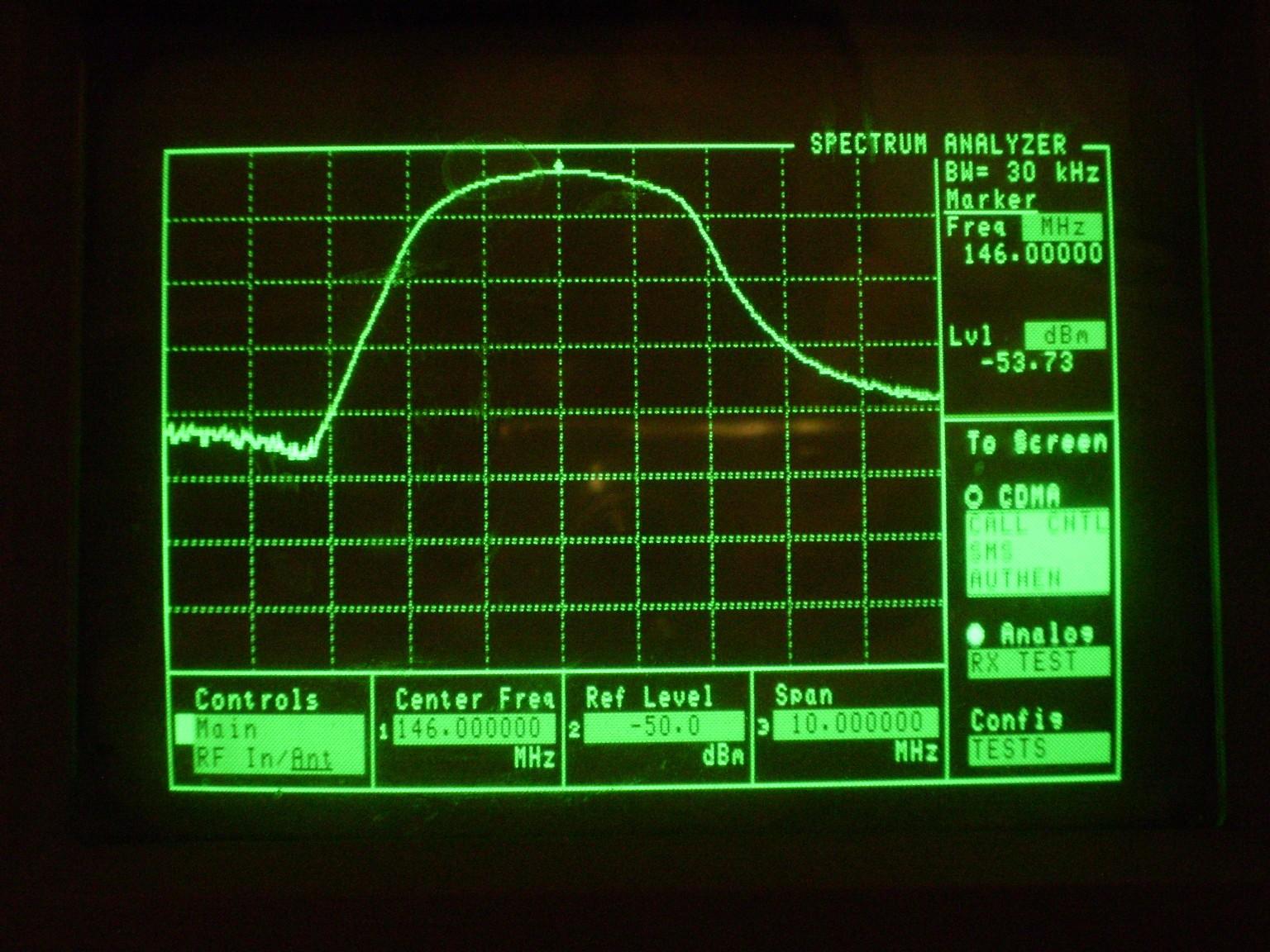
Once that is done set the following on the Spectrum Analyzer: Center frequency = Receive frequency, Span: 10 MHz, Tracking Generator Output Level: 0dBm, 10dB per division.
To get close, start with only the first slug, the one closest to the RF Input jack. Replace the retention nut on the slug and insert the slug into the helical casting. Tighten down the nut until the slug moves at the desired tension. Take the cable feeding the SA Input and hold it to the next hole in line and tune the first slug until the peak is at the center range. The signal should be -70 to -50dB down from +0dBm.
Repeat this procedure with following slugs advancing to next set of holes. Adjust for best flatness at the top of the graph.
When you reach the last slug, set the tracking generator to output -30dBm and connect the SA Input back to the LO Output of the receiver Front End module. Readings are now approximately 35dB down from the input. Adjust the last slug for maximum level, then proceed to adjust L1-L5 for best possible response. The response should be tuned to 3 MHz wide at the 3dB points.
To test for conversion gain, set the Spectrum Analyzer center frequency to 21.4 MHz. Offset the tracking generator so the output sweeps the center receiver frequency (146.04 MHz - 21.4 MHz = 124.64 MHz). The level of 21.4 MHz spike should be within 1dB of tracking generator output signal (-30dBm).
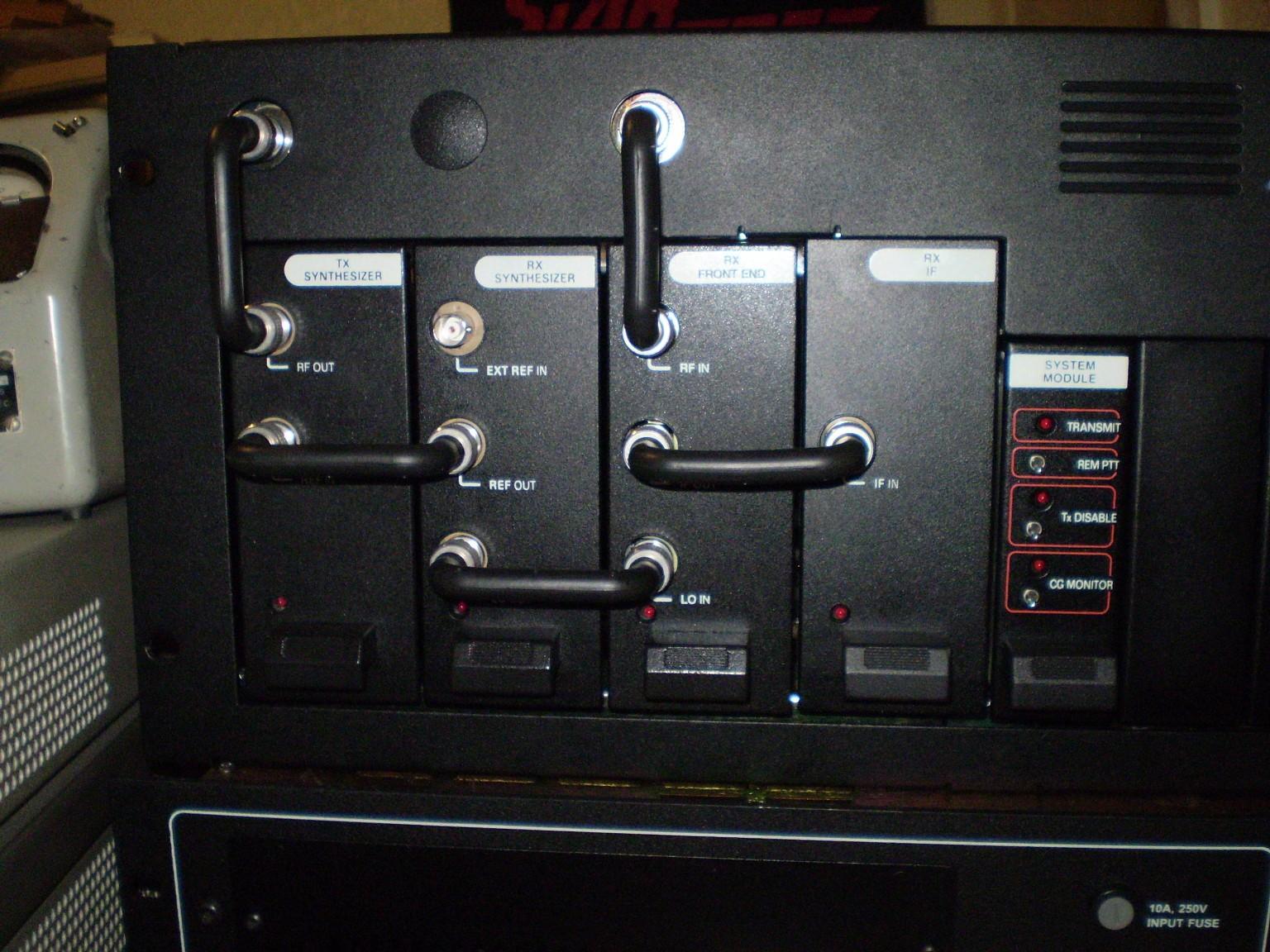
Phase 6 - T/R Frame:
Replace the modules into the T/R frame in the following order, Left to Right:
Large cards:
Small Cards:
Note, that some stations may have accessory cards in the blank areas.
Connect a service monitor with SINAD measuring ability to RF Input and take a connection from the station speaker for audio. Verify the receiver meets the factory specification of -116dBm (0.35uV); mine made -118dBm (0.28uV). Be sure to add cable losses into your figures.
External controller interfacing may be done following the instructions in this article.
Phase 7 - VHF Power Amplifier:
Please Refer to LBI38531A
The circuitry for the VHF Amplifier and Low Pass Filter works just fine in the amateur frequency range, so don't mess with it. Connect the output from the Transmit side of the T/R frame to the input of the Power Amplifier. In MASTRUTL.BAT from the Potentiometer screen, adjust Power Output to 99.
Unscrew the Low Pass Filter and lid from the PA assembly. Connect a Bird 43 with a suitable dummy load and 250W 125-250 MHz slug or equivalent to the output connector of the LPF. Key the repeater. Adjust the potentiometer on the Power Amplifier board until 135W is indicated on the meter, mine is labeled 'R217'. Adjust the Power Output value in the software until the desired power level is achieved.
Reattach the lid and Low Pass Filter and reassemble the repeater.
Acknowledgements and Credits:
All photographs by Matt Krick, K3MK. Revision V1.0, 01-Apr-2008.
Legal notice - All the material in this technical service bulletin is Copyright 2008 Matt Krick, K3MK. All Rights Reserved.
The author takes no responsibility for any damage during the modification or for any wrong information made on this modification. Your results may vary.
Commercial use of this bulletin is not authorized without express written permission of the author.
Furthermore, this work is specifically prohibited from being posted to www.mods.dk or any other 'limited free site'. Please ask for permission before posting elsewhere.
Contact Information:
The author can be contacted at DCFluX [ at ] yahoo [ dot ] com.
Back to the top of the page
Up one level (GE index)
Back to Home
This page first posted 20-Jul-2008
This web page, this web site, the information presented in and on its pages and in these modifications and conversions is © Copyrighted 1995 and (date of last update) by Kevin Custer W3KKC and multiple originating authors. All Rights Reserved, including that of paper and web publication elsewhere.