Back to Home
COR PLUS CTCSS
Detect Signal to the
Yaesu VXR-7000 Repeater
By Scott Lichtsinn KBØNLY

|
Up one level Back to Home |
Adding a COR PLUS CTCSS Detect Signal to the Yaesu VXR-7000 Repeater By Scott Lichtsinn KBØNLY |
|
The question was asked: "How do you get a COR signal that is conditioned by CTCSS on a Yaesu VXR-7000 repeater?"
I spent all morning working on one and I'm about ready to kick it across the floor. The schematic that NHRC and CAT have for hooking up the VXR-7000 is WRONG. Yes, Pin #11 on the DB25 Accessory Jack does work, but it's oblivious to how the repeater is programmed and goes low on ANY carrier, regardless of CTCSS presence. According to the Operations Manual, "It indicates that the receiver squelch is open. If the squelch control is properly set, this indicates a carrier on the receiver channel."
I was about to give up when I found a tidbit on the web that fixed it. It mentions a point inside which can be tapped to provide about 4.7v and pulls low to ground when receiving the correct CTCSS tone. Here are the details of how to do this. The same procedure applies to both the VHF and UHF repeaters.
Accessing the Signal:
The VXR-7000 has a Carrier Detected line available on the DB25 Accessory Jack. It does not bring a CTCSS detect line out of the box, or even a COR plus CTCSS combined signal. A suitable signal is available inside, but accessing it requires you to add a jumper wire to the CNTL board. The control board is on the top of the repeater and requires removal of the four screws on top and the three screws on each side.
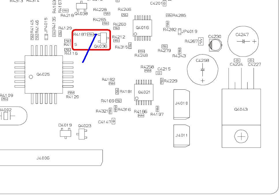
Attach one end of a wire to the base of Q4036, at the junction of R4187. This pin is a COR and CTCSS detection signal that is used to control the speaker audio and will work nicely as a CTCSS detection signal. The components are within the red enclosed area. The wire goes to the point in blue. Click on any of the images for a larger view.
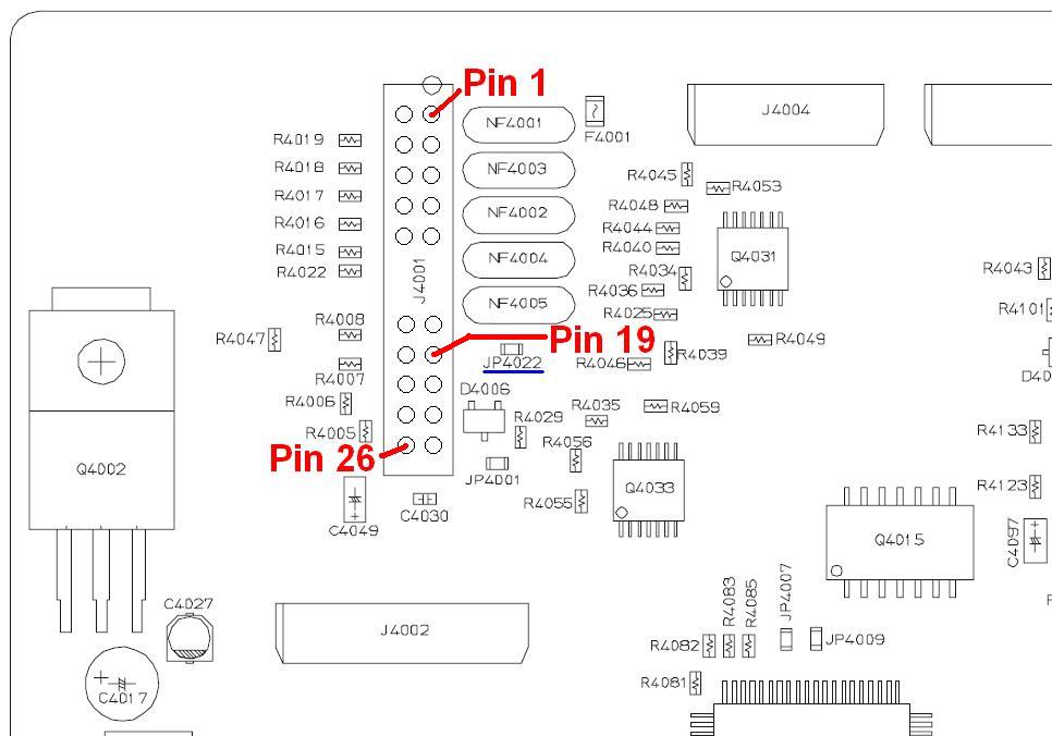
The other end of the wire goes to pin #19 of J4001. Pin 19 is connected to a surface-mount jumper - JP4022. Normally this jumper is not populated. The circuit pad closest to J4001 is the one that connects to pin #19 - this is where you connect the wire from above. The pin is marked in the diagram below.
Pin #19 of J4001 is already wired to pin #10 of the DB25 Accessory Jack and is marked as a Spare Wire. The wiring diagram shows how this is connected:
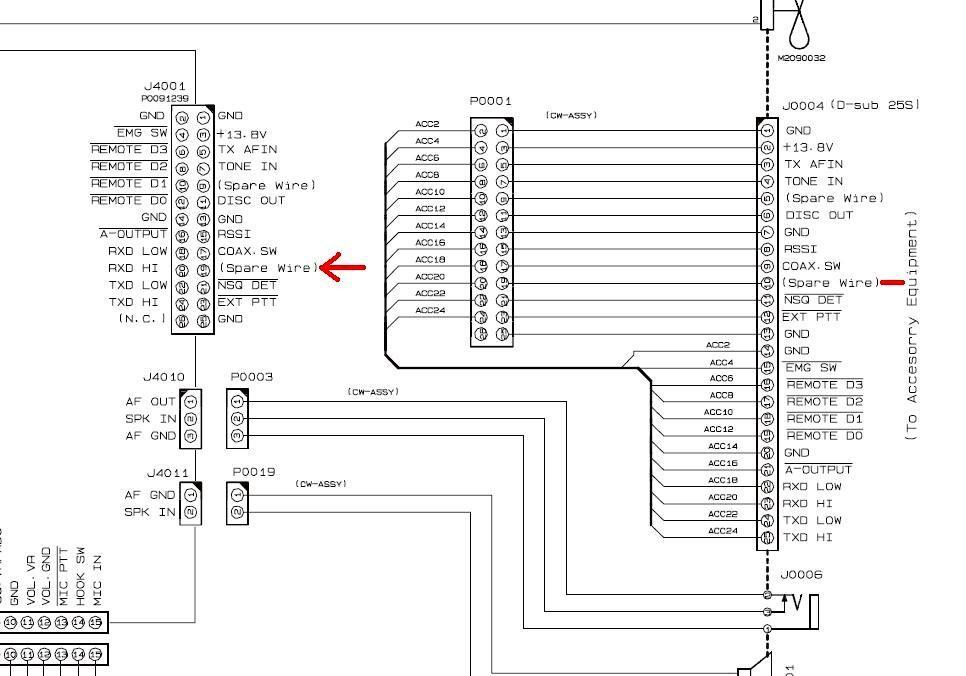
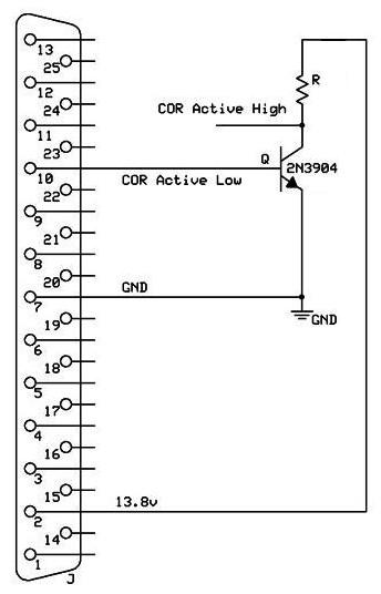
This puts an active-low CTCSS Detect signal on pin #10 of the DB25 Accessory Jack; it's pulled up internally to 4.5-5v. I suggest you use this along with a 2N3904 or similar NPN transistor to drive your controller. Connect the emitter to ground, the base to pin #10, and the collector gets pulled up to 12V with a 10k resistor; you bring the collector out to your controller as the new COR signal, referenced to ground. This gives you an active-high COR signal to the controller. If your controller can be configured for an active-low COR, then you can use pin #10 of the DB25 Accessory Jack directly without further conversion. Here is an example of how to convert for use with a controller that needs an active-high COR, such as NHRC controllers:
Acknowledgements and Credits:
Component layouts and wiring diagrams came from the VXR-7000 UHF Service Manual.
Thanks go to Bob WA1MIK for turning this into an article for repeater-builder.
Contact Information:
The author can be contacted at: kb0nly [ at ] mchsi [ dot ] com.
Back to the top of the page
Up one level
Back to Home
This page originally posted on Sunday 11-Jul-2010
Article text and layout © Copyright 2010 by Scott Lichtsinn KBØNLY.
HTML conversion © Copyright 2010 by Robert W. Meister WA1MIK.
This web page, this web site, the information presented in and on its pages and in these modifications and conversions is © Copyrighted 1995 and (date of last update) by Kevin Custer W3KKC and multiple originating authors. All Rights Reserved, including that of paper and web publication elsewhere.