Up two levels (Main Motorola Index)
Back to Home
External Repeater Controller Interfacing Signals
Compiled, HTML'd and Maintained by Robert Meister WA1MIK (SK)
Currently Maintained by Mike Morris WA6ILQ

|
Up one level (MTR2000 Index) Up two levels (Main Motorola Index) Back to Home |
A Summary of the MTR2000 External Repeater Controller Interfacing Signals Compiled, HTML'd and Maintained by Robert Meister WA1MIK (SK) Currently Maintained by Mike Morris WA6ILQ |
|
This is a collection of interface connection points for the MTR2000 stations. The MTR stations come in multiple flavors, VHF, UHF, 900 MHz, low power and high power. They interface identically. This information been compiled from other articles and web posts that I've run across. I've checked each of them for reasonableness and made corrections where appropriate. The suggestions in each category are presented in no special order.
Comments, updates or other contributions on this page are welcome!
For simple repeater controller interfacing, the following signals are usually required:
Important Notes:
Some signals are marked "not recommended" and you should avoid these unless there are no other options available.
All audio signals should utilize a 10µF 25 Volt electrolytic capacitor in series with any external equipment as the MTR2000 station's audio circuitry is biased at +4.8 VDC. Point the positive end towards the MTR2000. Some controllers may already have DC blocking capacitors in the audio lines so always check first.
Logic signals are measured relative to ground.
Most connections are made to the System Connector (J5) located on the rear of the station. Others will be on any exposed connector such as the MRTI (J7), Wire Line (J6), and front panel service microphone (P5602, not recommended). That's about all you can readily access.
NOTE: If you station has a Wire Line board installed (top slot) you must set it for 4-wire mode even if you are not using it.
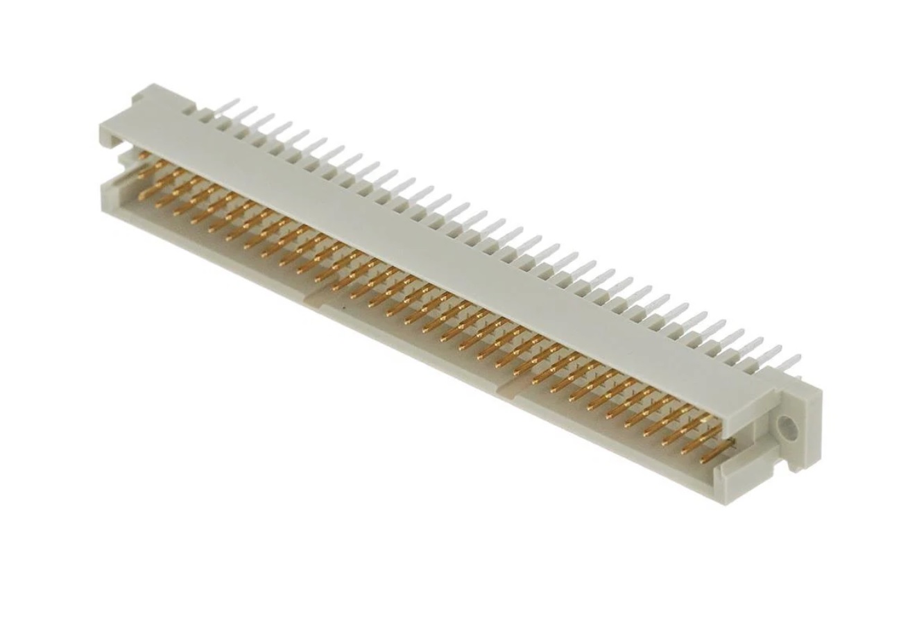
One common name for the actual connector that Motorola uses as the System Connector is a "3x32 DIN Eurocard Connector". The male mate for the 96-pin system connector can be obtained from Motorola as part #TKN9205A or 3083908X02, which includes about 30 pre-crimped pins and wires for at least $50US.
You can purchase just the connector from Mouser for about $5US (2014 price)
as part #
571-5650889-5 (Off-site pointer, opens in a new browser tab).
Digikey has them as well; search for DIN 41612 or
5650889-5 (Off-site pointer, opens in a new browser tab). Just solder wires to the pins where you need them.
Both of the pointers above are to the connectors that have the pins sitcking out the back of the connector body, there is another version that has right angle pins for soldering onto a circuit board.
The MRTI connector is a DB25F, so you will need a DB25M connector to plug into it.
Other Resources:
The following articles provide useful interfacing information for the MTR2000:
Programming Hints:
You'll need a Wire Line board installed to use the Wire Line connections for audio and you will need to set it for Full Duplex (4-wire).
If you'll be using the MRTI interface, it has to be enabled in the RSS. In the Station Configuration screen, make sure the "MRTI Enable" box is checked. In the same screen, you want to set the station up as a base station, NOT a repeater. The external controller will want to see the station as a separate receiver and transmitter (a full duplex station).
In the Personality, Channel Information, Audio screen, set the Analog RX Activation to Carrier & PL/DPL. Make sure you check the Pre-Emphasis, De-Emphasis, and MRTI boxes (as required) for the active channel. Do NOT put a call sign into the station ID field (not even a space character) – If there is anything there (from the previous owner) delete everything.
In the Personality, Channel Information, PTT screen, make sure the Timeout boxes are unchecked. The external controller will handle all timeouts. Also, make sure you set the External PTT Mapping drop-down box to "Microphone". Per the RSS Help file: "The MRTI TX audio path uses the station's microphone path. When an MRTI PTT occurs, the station switches the input to the MRTI TX Audio from the Microphone Audio. When the PTT ends, the audio path is switched back to the Microphone Audio."
PTT Input:
TX Audio Input:
There are several ways to get audio into the station, all through its standard connectors. These are:
If you use the A17 Aux Audio pin of the System Connector that disables the internal PL encoder. One workaround is to use the MRTI connector for RX and TX audio interfacing. If you want to use flat audio (input through A17) and have PL encode then you will have to mix your flat audio source and an external PL encoder yourself with a simple restive mixer, or use the Wire Line input for audio.
Carrier Detect (COR) Output:
Some repeater controllers have one input for COR and a separate input for PL / DPL Detect. The station's microprocessor decodes the PL / DPL There's both a COR output that only depends on carrier, as well as a COR output that requires a proper PL / DPL tone to be present along with that carrier. This one responds to any RF signal on the receive frequency. If you'll be using PL / DPL on your repeater, don't use this as the only COR signal.
RX Audio Output:
Receive audio comes in two flavors: raw or flat (discriminator or detected) audio, and de-emphasized audio. Neither is squelched or muted.
Carrier with Coded Squelch Output:
Some repeater controllers have one input for COR and a separate input for PL / DPL. Detect. The station's microprocessor decodes the PL / DPL. There's both a COR output that only depends on carrier, as well as a COR output that requires a proper PL / DPL tone to be present along with that carrier. This one requires a carrier and PL / DPL. If you'll be using PL / DPL on your repeater, this is the signal you want to use to drive the tone decode input on your external controller.
+12v DC Power Output:
+14 Volts DC is available at limited current (the regulator can provide up to 1 Amp total) to power your controller, receiver preamp, whatever.
Ground:
Don't rely on the chassis mounting screws or a power supply ground. Pick up a ground on one of the connectors. Typically the analog grounds are used for TX and RX audio and the logic grounds are used for PTT and COR signals. The MTR2000 doesn't provide separate analog and logic grounds.
Acknowledgements and Credits:
MTR2000, PL, DPL, and a bunch of other terms are trademarks of Motorola, Inc.
Contact Information:
The original author is a silent key as of June 2021. The page maintainer can be contacted by way of the "Currently Maintained by" link above.
Back to the top of the page
Up one level (MTR2000 Index)
Up two levels (Main Motorola Index)
Back to Home
This page conceived 09-Oct-2014
Article text and hand-coded HTML © Copyright 2014 by Robert W. Meister WA1MIK (SK).
This web page, this web site, the information presented in and on its pages and in these modifications and conversions is © Copyrighted 1995 and (date of last update) by Kevin Custer W3KKC and multiple originating authors. All Rights Reserved, including that of paper and web publication elsewhere.