Back to Home
TK-690H 40-50 MHz
Mobile Radio to 6-Meters
Low-Pass Filter Mods
By John Haserick W1GPO

|
Up one level Back to Home |
Converting the Kenwood TK-690H 40-50 MHz Mobile Radio to 6-Meters Low-Pass Filter Mods By John Haserick W1GPO |
|
Background:
The TK-690H features 100 watts power out, but unless you do the following modifications to the low-pass (harmonic) filter, the radio will be inefficient and may not easily make full rated power.
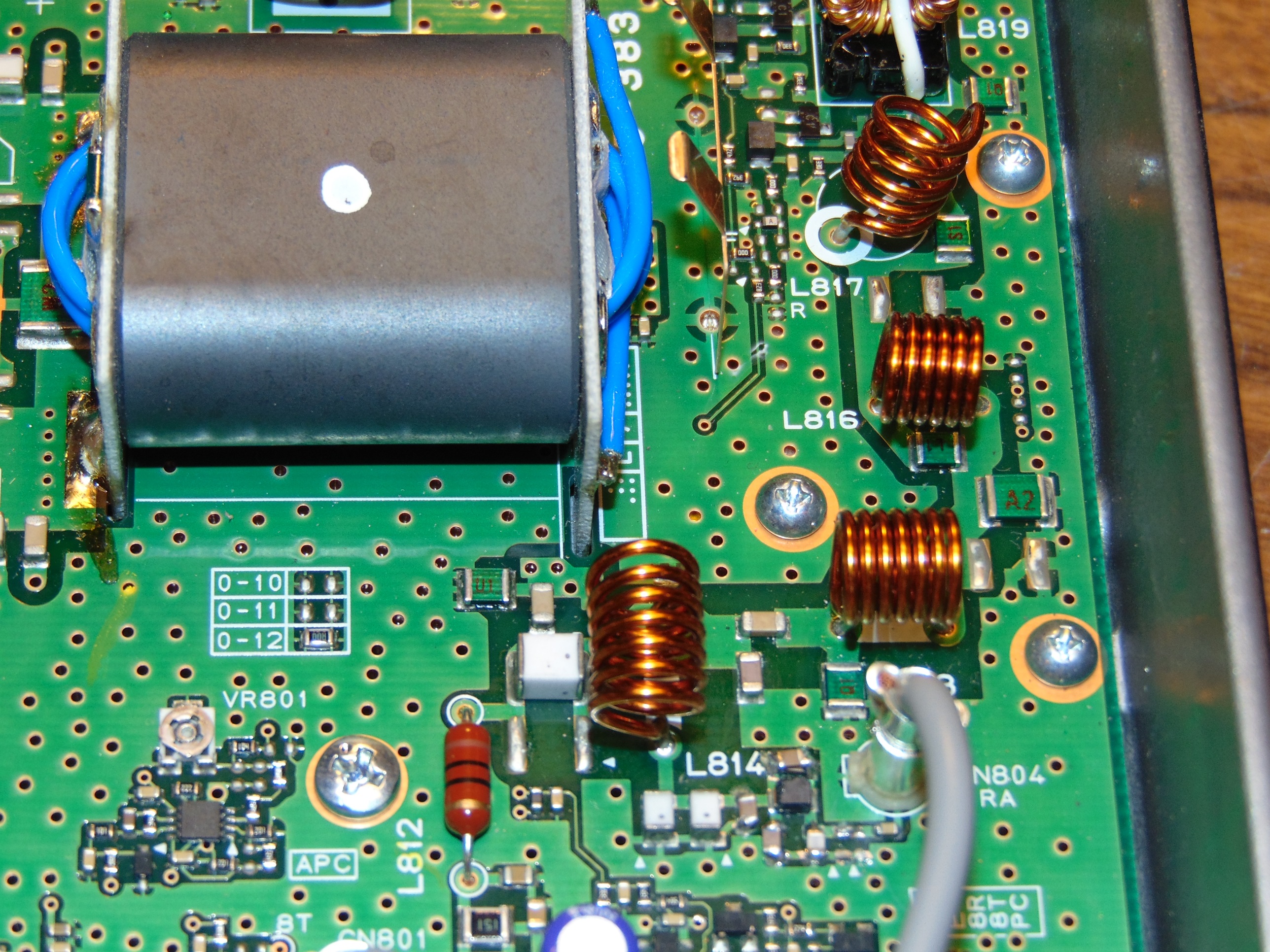
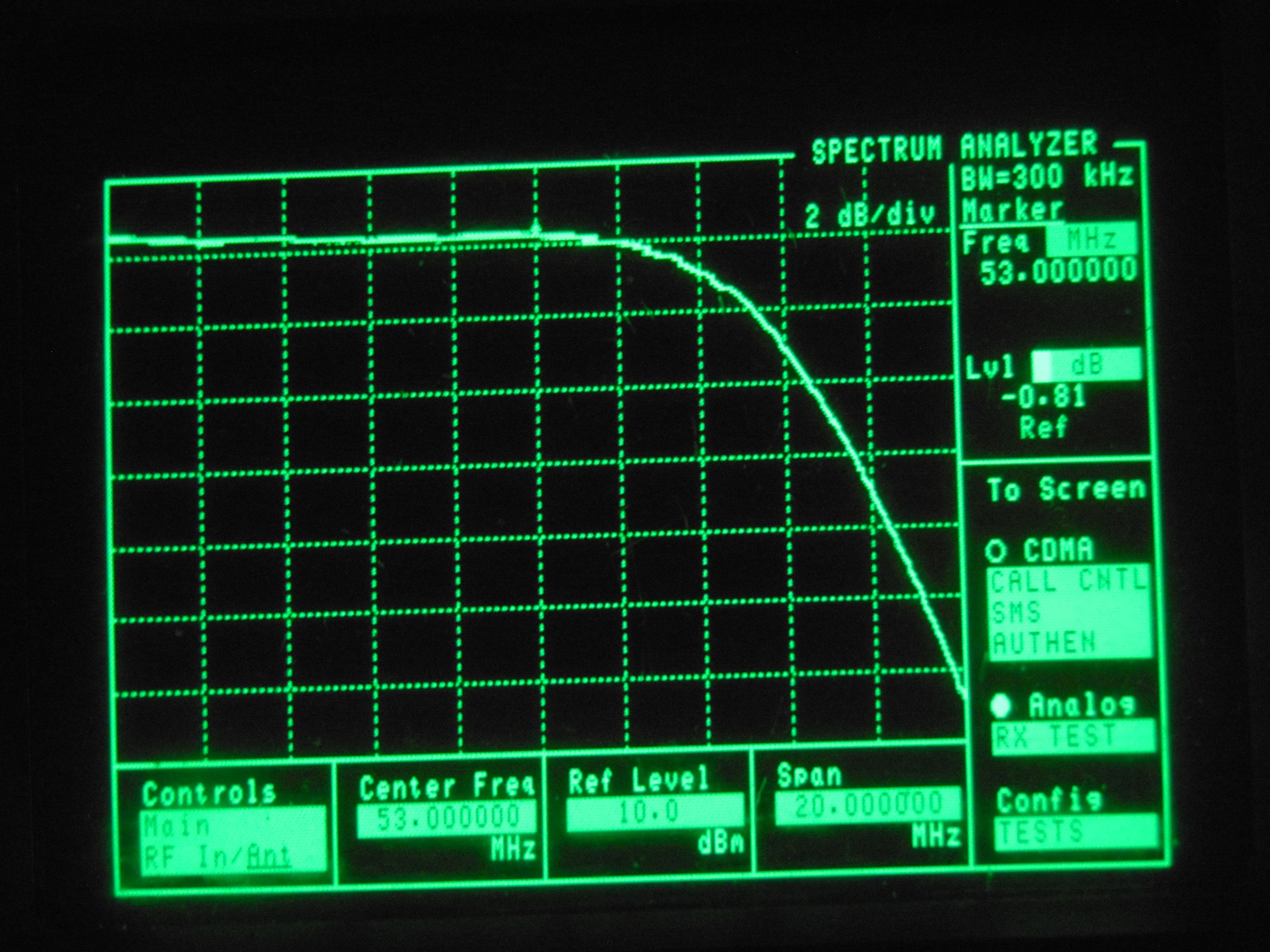
Up to now, the low-pass filter modifications have been a confusing situation for us, as different serial number TK690H radios have different components, but I finally had the time to dig in and clear up the mysteries, so I thought I would share the results...Basically the radios with serial numbers that are all numbers between 20.......... and 95.......... apparently have the same PA board components. The output PA transistors are bipolar. The second version radios ("B" revision) with serial numbers starting with either the letter A........ or B........have PA boards with MOSFET PA transistors. There is a receive only miniature harmonic filter with a small black plastic case located adjacent to the receiver coax female connector (see pic). This is present on both types , but they differ in components. The B version also have a pair of back to back protective diodes between the mini harmonic filter and the RX connector. This mini harmonic filter has between a 0.5 and 2 dB roll off loss starting at 50 MHz so 6M receive is between 0.5 and 2 dB less sensitive than between 40 and 50 MHz. (usually closer to 2 dB) We have figured out the component changes to eliminate this extra 6M receive degradation. It just involves changing out a few chip caps on the mini-harmonic filters. If the RX makes rated 0.25 uV for 12 dB SINAD no mini harmonic filter component changes needed, so best left alone. Apparently the parallel cap (C899 or C62) is used to increase harmonic reduction as a parallel tuned circuit, but its resonance is too close to 6 meters for its broad resonance not to effect 6M, so these values were reduced to raise the resonant freq, but in so doing it threw off the entire resistance and reactance that need compensation with the other cap changes. We used an antenna analyzer connected to the radio ant connector and a 50 ohm load at the RX connector on the PA board and a whole lot of juggling cap values to arrive at the best SWR and nearly zero reactance on 6M, but you need to adjust the air coils for the TX first, then leave them alone.
On the original revised radios (revised from serial number 1.......) these are the changes
C60 56pF to 47pf
C62 82pF to 68pF
C65 56pF to 47pF
On the A and B SN revision B radios ....
C899 51pF to 43 pF (33+10)
C895 18pF to 22 pF
On both version radios sensitivity should go from 0.28 uV to 0.23 uV for 12 dB SINAD on average and there should also be an improvement in return loss as measured by a return loss bridge on the radio antenna connector. Some receivers, when measured at the receive board connector, have return loss of only 12 dB and others make 20dB so if you get a RL of only 12 dB at the antenna connector the problem could be in the RX board, not the PA board. Not a problem unless duplexing.
For tune up of the harmonic filter, first adjust spread on the 4 harmonic filter air coils for lowest amp draw on the high power output settings. Some radios will not require any spreading and some will, but spreading should not be more than shown on the B radio picture, and different coils might need spreading on different radios due to component variations. No coil turns should be removed.
(The PA board picture shows a lack of the 2 back to back protective diodes, because I removed them initially figuring the slight lack of RX sensitivity might have been due to them. It was not and since they were only gnat size, I was not able to replace them!)
John W1GPO
Credits and Acknowledgements:
Thanks to Roger WA1NVC who performed the radio conversion.
Thanks to Kevin W3KKC who turned these notes into an article for repeater-builder.
Contact Information:
The author can be contacted at: jhaserick84 (at) comcast [dot] net
Back to the top of the page
Up one level (Kenwood Index)
Back to Home
This page created on 28-May-2024.
Article text and photos © Copyright 2024 by John Haserick W1GPO.
Converted to repeater-builder format by Kevin Custer W3KKC.
This web page, this web site, the information presented in and on its pages and in these modifications and conversions is © Copyrighted 1995 and (date of last update) by Kevin Custer W3KKC and multiple originating authors. All Rights Reserved, including that of paper and web publication elsewhere.