Back to Home
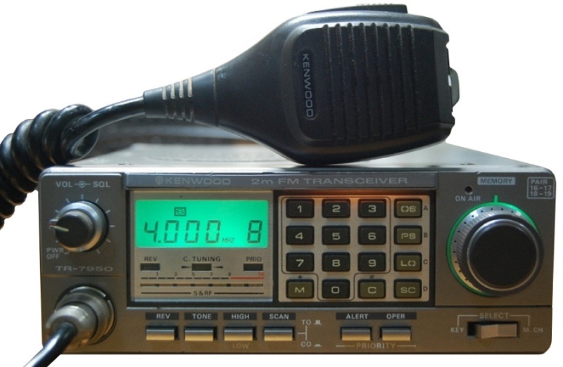
TR-7930 and TR-7950
By Mike Morris WA6ILQ

|
Up one level (Kenwood Index) Back to Home |
Notes on the Kenwood TR-7930 and TR-7950 By Mike Morris WA6ILQ |
|
Photos courtesy www.rigpix.com
The TR-7930 and TR-7950 were an interesting pair of 2 meter radios that were made in the 1982-1985 time frame. The TR-7930 offered 25 watts or 5 watts, and the TR-7950 offered 45 watts or 5 watts. Receive current draw was about 1/2 amp, and the TR7950 transmitter could pull as much as 9 amps. The European region units could transmit and receive from 144 to 146 MHz, the USA region radios offered 144-148 MHz. There was a "Civil Air Patrol modification" that allowed the USA region radios to operate in 142-149 MHz so that the CAP members could access their repeaters (inputs were around 143.1-143.5, outputs were around 148.1-148.5). I do not know if the CAP Mod worked in the European region units.
Both the TR-7930 and TR-7950 use 12 volt 60mA incandescent lights to
illuminate the display and the DTMF pad. Replacements from Kenwood were
EXPENSIVE. Fortunately Radio Shack had an almost identical bulb
(and it's close enough that it works perfectly) as part number
#272-1092 (two bulbs). Some hobby stores and most model railroad
shops have a similar bulb. McMaster-Carr (an industrial supplier) has a
very-very-close bulb in their
#7219.
Under $9 for a package of 10.
Or you can do what Tony King W4ZT (SK) did - replace them with
LEDs each with an appropriate dropping resistor. He wrote
an article using blue
on the display and knobs and white on the keypad.
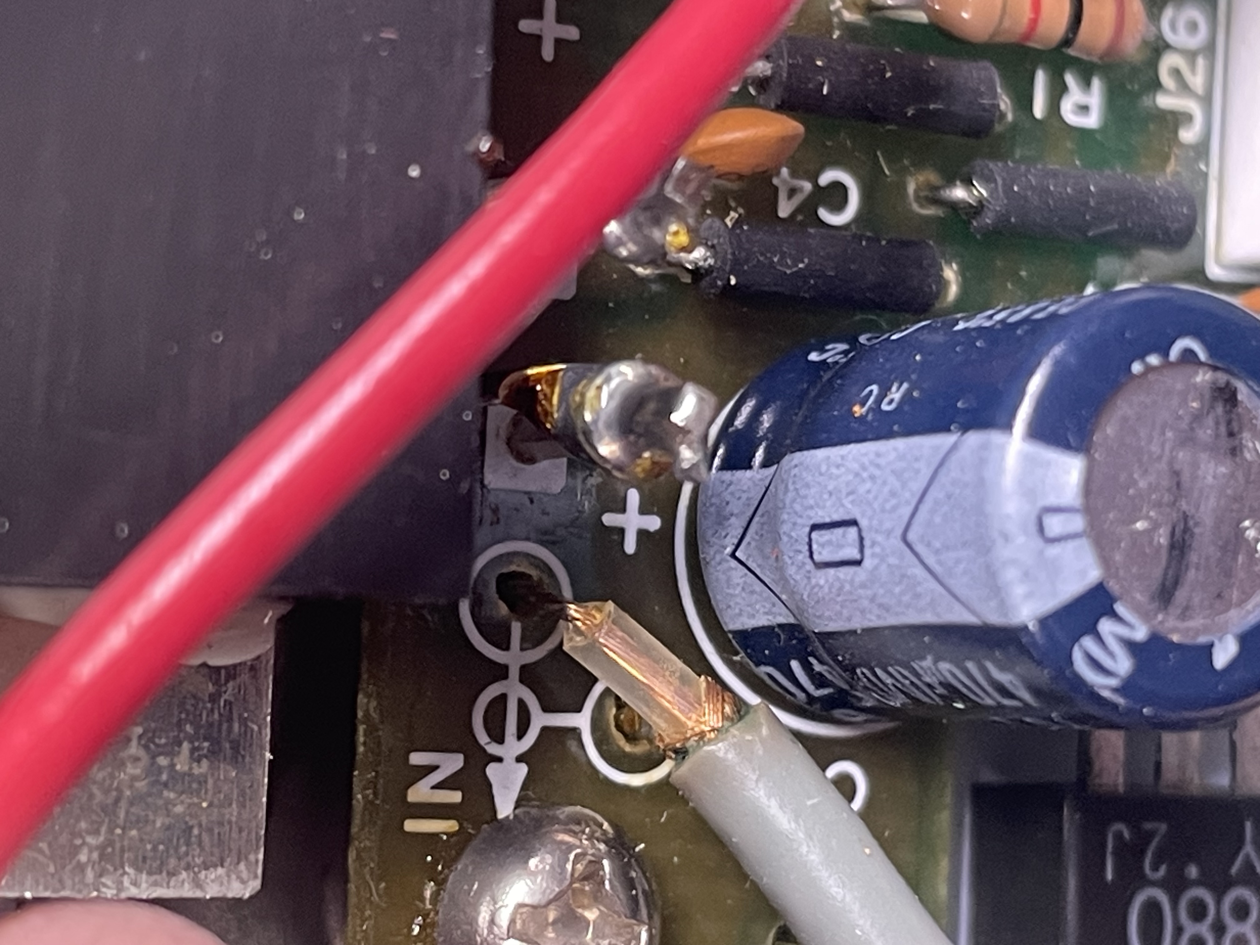
One thing to check in your 7950 (and maybe the 7930): There's a manufacturing screwup that I found on a brand new TR-7950 within 20 minutes after I opened the box. On the power output board where the PA module is connected there was (note the word "was") a 470 µf capacitor designated C1. The silkscreen on the board has a "+" on the connection to ground and naturally the factory assemblers installed the capacitor to match... backwards. When you think about it, this is obviously wrong as ground is the minus lead not the positive lead.
I plugged the brand new radio into the bench supply and turned it on. A minute or so later there was this loud fart from inside the radio and a familiar smell. I powered off the supply and opened up the radio. The cap had swolen up and burst due to reverse polarity (due to incorrect factory installation). I scavenged a replacement cap and almost blew it up until I caught the error in the silk screen.
If you have a 7930 or 7950 you would do well to pull off the back and inspect the cap installed at C1. Its the only large filter cap on this board so its easy to locate. If it's installed with the negative lead adjacent to the silk screened "+" (the ground foil) it's OK. If it's backwards I'd replace it, especially if the case looks bulged.
In a new-to-you radio I'd open it up, check C1 and while you have the cover off replace the memory backup lithium battery.
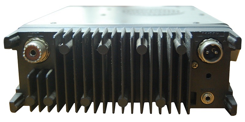
The radio has a rather unusual 2-pin microphone-style DC power input connector. The mobile bracket was the MB-9, and if you want to make your own the case is just under 7 inches wide. The optional three frequency CTCSS encoder (diode programmable) was the TU-79. I used a Com-Spec tone encoder box that used a rotary switch to select the tone.
The photo below (courtesy of Rick Tressler WA3UOO) shows the "+"
next to the negative side of C1.
Click on the photo to enlarge it.
Contact Information:
The author can be contacted here: Mike Morris WA6ILQ.
Back to the top of the page
Up one level (Kenwood Index)
Back to Home
This web page originally posted on 03-Jan-2010.
Article text and hand-coded HTML © Copyright 2010 by Mike Morris WA6ILQ and date of last update.
This web page, this web site, the information presented in and on its pages and in these modifications and conversions is © Copyrighted 1995 and (date of last update) by Kevin Custer W3KKC and multiple originating authors. All Rights Reserved, including that of paper and web publication elsewhere.