Mike,
I have an addendum to KD9KOO's helpful article on "Building your own BridgeCom BCR-series Repeater Programming Cable."
Jared wrote that "BridgeCom reversed the order of the pins on their repeaters." Actually, BridgeCom didn't reverse the order of the pins. They simply didn't share any information at all.
The pinout table published by Maxon, and shared by Jared, is unambiguous and just plain wrong. One shouldn't blame BridgeCom for Maxon's error. Maxon's drawing shows the pins numbered from left to right, looking into the receptacle with the tab down. That is consistent with the modern convention for numbering the pins in an RJ-45 jack. However, the pin numbers listed in Maxon's table assume the pins are numbered from right to left, which is clearly not what the drawing shows. Maxon is not the first radio manufacturer to number the pins from right to left. But at least when Motorola did that (on the MaxTrac radios, for example), their drawing matched the listed pin numbers!
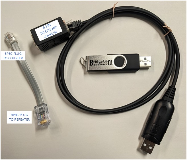
I was recently asked to set up a couple of BridgeCom BCR-40U repeaters purchased by a friend. They came with what appears to be BridgeCom's version of the programming cable. But here's the thing – their programming cable has a 6P6C modular plug, while the mic/programming jack on the repeater has an 8P8C jack (what most people call an RJ45 jack).
While one can insert a 6P6C plug into an 8P8C jack, it isn't a perfect fit. Moreover, in my experience, when one does that, the plastic housing of the plug bends the outermost two electrical contacts in the jack, potentially causing those two pins to become intermittent when an 8P8C plug is subsequently inserted. That could interfere with functions of the BridgeCom microphone, which makes use of all eight pins.
So I grabbed a 6-pin RJ25 telephone coupler from my junk box and made up a short 6-conductor adapter cable with a 6P6C plug on one end and an 8P8C plug on the other end, with the outer two pins in the 8P8C plug unconnected. That lines up with the pinout as described by Jared and enabled me to program the repeater without damaging its mic jack.
Incidentally, I have read the adverse user reports online about BridgeCom's quality, but have not formed my own opinion yet. I will note that when I opened up these two repeaters for inspection, I found loose hardware in one. While that was easily corrected, it did not make a good first impression!
For the record, my units did have labels with FCC ID number 099TM-8402A. But as others have noted, that ID is associated with the two TecNet International Inc. / Maxon mobile radios that are (presumably??) a component of the repeater.
I hope this information might be useful to users of your great website.
73,
Al Taylor KN3U
Contact Information:
The author, Al Taylor KN3U, can be contacted at his QRZ email address.
Back to the top of the page
Up one level (BridgeCom Index)
Back to Home
This page created on Wednesday 30-Jul-2025.
This web page, this web site, the information presented in and on its pages and in these modifications and conversions is © Copyrighted 1995 and (date of last update) by Kevin Custer W3KKC and multiple originating authors. All Rights Reserved, including that of paper and web publication elsewhere.