| Up one level (BridgeCom Index) Back to Home |
Building your own Bridgecom BCR-series Repeater Programming Cable By Jared Smudde KD9KOO HTML'd and Maintained by Mike Morris WA6ILQ |
This "side project" was born out of an attempt to avoid purchasing a third programming cable for the BridgeCom Systems, Inc. BCR-Series repeaters, after losing the first two. Bridgecom sells them for either $25 for just the cable or $60 for the programming cable and software combo. Bridgecom doesn't have the pinout for the front microphone jack published nor would they give it out. So that lead into the journey of homebrewing a programming cable.
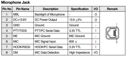
My first stop was the user manual for the Maxon TM-8000 series radios used by Bridgecom. Maxon was kind enough to publish the microphone jack pinout on the TM-8000 radios.
Armed with this knowledge, I took a CAT6 ethernet cable and plugged it into the repeater and the other end into a RJ45 breakout board. I then took the Ground, TXD0, and RXD0 line and used a Kenwood TKR-x50 repeater programming cable with an almost identical pinout to hook into the serial port on the programming computer. To no surprise, it didn't work, the programming software couldn't read the repeater.
I spent some time trying to find a somewhat detailed photo of the Bridgecom programming cable and when that turned up empty, I tried looking for a detailed photo of the Maxon OEM programming cable for the TM-8000 series radios. That search also went nowhere. I tried looking on the Repeater Builder Groups.IO and only found a post from 2020 also looking for a pinout but no solutions were given at the time.
After staring at the above pinout for a while, I threw the towel in and made a new post on the Repeater Builder mailing list that is hosted at Groups.IO asking for a photo of the official repeater programming cable from Bridgecom to see if I could get some help that way.
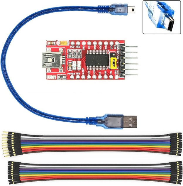
Shortly, I received a reply from Scott Zimmerman N3XCC stating that he used a 3.3V USB to TTL converter and hooked up the Ground, TX, and RX lines and it worked without issues. I went to Amazon and purchased a USB to TTL kit for less than US$7 shipped to my door.
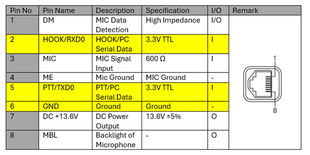
While waiting for it to arrive, I went ahead and was tidying up my RJ45 breakout board when I made a discovery. The pinout on the front of the Bridgecom's are reversed compared to the Maxon pinout. So, after using the multimeter and some probing, I was able to determine that Bridgecom reversed the order of the pins on their repeaters.
So, this is the pinout I found that Bridgecom uses. I've verified it on the two repeaters I had on my desk, one being an early v4.07 VHF model and the second being a slightly newer v4.37 UHF repeater.
I took the TX pin on the TTL converter and attached it to the Bridgecom RXD0 line, the RX pin on the TTL converter and attached it to the Bridgecom TXD0 line, and finally the TTL converter ground line to the GND pin on the Bridgecom. I installed the drivers for the TTL converter and the Bridgecom programming software and was able to read and write to the repeaters. Overall, it was a quick, easy, and cheap alternative to the official Bridgecom cable and you never know when you may need a TTL converter for another project. Thank you, Scott, for the tip!
Contact Information:
The author, Jared Smudde KD9KOO, can be contacted at his email address on QRZ.com.
Back to the top of the page
Up one level (BridgeCom Index)
Back to Home
This page created on Saturday 08-Feb-2025.
Last edited on 09-Feb-2025
This web page, this web site, the information presented in and on its pages and in these modifications and conversions is © Copyrighted 1995 and (date of last update) by Kevin Custer W3KKC and multiple originating authors. All Rights Reserved, including that of paper and web publication elsewhere.