Back to Home
Linear Regulated Power Supply
from Using an NE550
to an LM723 Regulator IC
By Robert W. Meister WA1MIK

|
Up one level Back to Home |
Converting a VHF Engineering Linear Regulated Power Supply from Using an NE550 to an LM723 Regulator IC By Robert W. Meister WA1MIK |
|
Background:
I needed another power supply like a hole in the head (I think I have nearly a dozen Astron supplies), but for $80 the price seemed reasonable and it gave me the subject for another article (woo hoo).
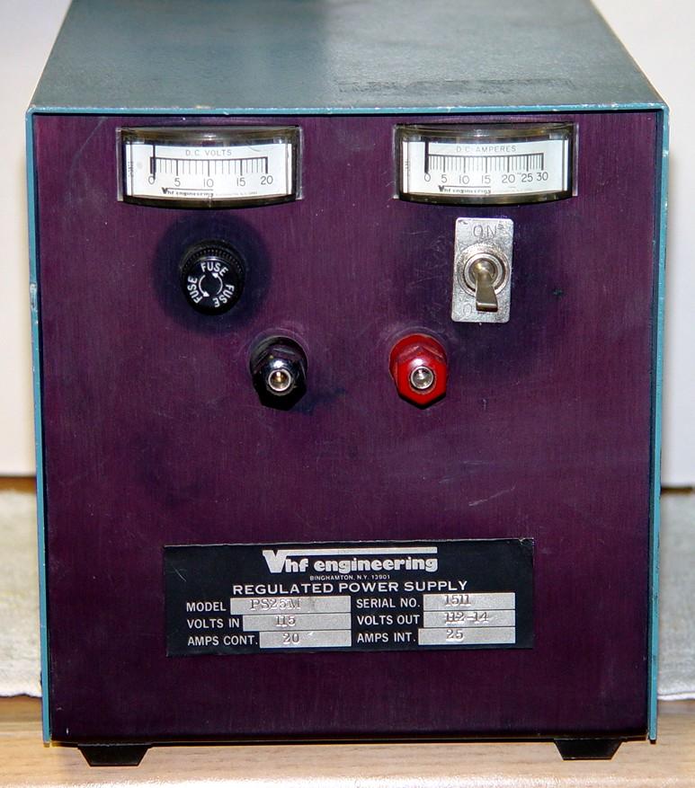
This is a PS-25M, which I didn't even know existed. It seems to be a PS-25C with two front-panel edge-wise meters that display output voltage and current. VHF Engineering power supplies were designed around the now-unobtainable NE550 regulator IC. When I received this PS-25M, I naturally opened it up but was unpleasantly surprised to see a Fairchild uA723 regulator IC already present; this is the same IC as the LM723. Apparently in the late 1970s, VHF Engineering converted their design to use the 723 IC. Well, there goes my conversion article. I will document what's different between this unit and the NE550-based units so you can convert your supply when it dies.
This supply is very similar to the Astron RS-35M although the current rating is lower: 25A peak for the PS-25 vs 35A peak for the RS-35. Both have four series-pass transistors although the heat sink on the Astron is quite a bit larger. There is NO over-voltage crowbar in my PS-25M even though there is a sticker on the bottom claiming it has an OVP-12 device. There is a 470uF 16V axial-lead capacitor across the output binding posts; I replaced it with a 470uF 35V component.
Construction is similar to Astron supplies. The front panel has the meters, output binding posts, AC fuse, and AC power switch. The power transformer is mounted directly behind the front panel. The rectifier and main filter capacitor are near the rear. The regulator board is mounted on the capacitor's screw terminals, just like Astron does on their units. The AC line cord is hard-wired and exits the rear of the chassis under the removable heat sink, which holds four series-pass output transistors: generic 2N3055 parts mounted in sockets.
Parts Differences:
Here's a full passive component parts list. Resistors are in ohms, 1/4w, 5% unless otherwise indicated. Capacitors are in uF with the working voltage following. The parts in red text have significantly different values between the original PS-25 that used the NE550 and the newer PS-25 that used the LM723. Other parts values might be slightly different due to parts availability.
| ID | PS-25C | PS-25M |
|---|---|---|
| IC1 | NE550 | LM723 |
| R1 | 1,000 | 5,600 |
| R2 | 2,000 pot | 2,000 pot |
| R3 | 10,000 | 4,700 |
| R4 | 5,600 1/2w | 5,600 1/2w |
| R5 | 330 | 330 |
| R6 | 3,000 | 3,000 |
| R7 | 100 1w | 100 1w |
| R8 | 0.1 5w | 0.1 5w |
| R9 | 0.1 5w | 0.1 5w |
| R10 | 0.1 5w | 0.1 5w |
| R11 | 0.1 5w | 0.1 5w |
| R12 | 220 2w | 220 2w |
| C1 | 25,000/40 | 30,000/50 |
| C2 | 0.001 | 0.001 |
| C3 | 500/16 | 470/16 |
| C4 | 0.001 | 0.001 |
| C5 | 0.01 | 0.01 |
| C6 | 0.01 | 0.01 |
The main filter capacitor (C1) value is not critical but VHF Engineering increased both its capacitance value and its voltage value. Only TWO resistors have a different value: R1 and R3. I had already calculated initial values for these two parts; lo and behold, mine were identical to what VHF Engineering chose. Well, that was easy.
The front panel ammeter has a 0-30A scale with a built-in shunt. It is in series with the common output lead (from the series-pass transistor resistors R8 thru R11) and the front panel output binding posts. My meter initially read 2A high at all load values because the zero adjustment was incorrect; I took the meter apart and adjusted it, but it still reads high. The front panel voltmeter has a 0-20V scale and is fairly accurate, within 0.5V. It is wired directly across the front panel output binding posts. The raw DC voltage across the main filter capacitor is around 26.5VDC no-load, decreasing to around 21.7VDC with a 20A load.
Refer to the PS-3, PS-15, or PS-25 schematics for more detailed regulator board information.
Preliminary Testing:
After receiving the unit, I opened it up and gave it the once-over. I repaired any wiring issues, tightened all hardware, installed new rubber feet, put plastic covers over the four TO-3 series-pass transistors on the heat sink, and eventually unsoldered the regulator IC and installed a 14-pin socket, which will make future repair much easier. I also checked the soldering job on the board and the electrolytic capacitors for value. I figured out the meter wiring and made notations on a schematic. I then performed a load test and measured the output voltage drop. I suspect the Astron design might be superior because it provides the regulator IC with a separate higher supply voltage than the series-pass transistors receive.
| Load Current DC Amps |
Output Voltage DC Volts |
Noise+ Ripple AC mV |
Input Current AC Amps |
Impr. 1 Voltage DC Volts |
Impr. 2 Voltage DC Volts |
|---|---|---|---|---|---|
| 0 | 13.799 | 1.9 | 0.3 | 13.802 | 13.799 |
| 5 | 13.747 | 3.5 | 1.6 | 13.777 | 13.781 |
| 10 | 13.695 | 6.1 | 2.9 | 13.753 | 13.763 |
| 15 | 13.641 | 9.1 | 4.1 | 13.728 | 13.745 |
| 20 | 13.590 | 12.0 | 5.3 | 13.702 | 13.728 |
| 25 | 13.465 | 15.0 | 6.4 | 13.668 | 13.708 |
The supply went into over-current fold-back at 29 amps of load current, folding back to 5 amps, not 1 amp as the manual states. It could be adjusted from about 11.7V to just over 16.4V, which is perfectly acceptable to me considering there are no over-voltage protection components. R1 and R3 values could be tweaked to reduce the adjustment range to 11V to 15V if desired.
Regulator ICs:
The NE550 and LM723 are physically identical; both have 14 pins and the pin functions are the same. The only difference I can find is that the reference voltage on the NE550 is (nominally) 1.63V, while the reference voltage on the LM723 is (nominally) 7.15V. This means some resistor values will need to be changed to produce the desired reference voltage to the inverting input of the regulator IC. Once the supply is made to work with the LM723, other features such as front panel voltage adjust and current limiting can easily be added by copying the circuit from similar Astron power supplies, such as the VS-35.
Adjustment Range Theory:
Refer to the schematic here. The series resistors R3, R2 (pot), and R1 are across the output of the power supply. The arm of the pot feeds the inverting input of the regulator IC, so when this pin goes lower (towards ground), the IC causes the output voltage to increase to keep the arm of the pot equal to the reference voltage. The resistor on the ground end of the pot (R1) determines the maximum output voltage, which should be about 15VDC. The resistor on the high end of the pot (R3) determines the minimum output voltage, which should be about 11VDC. In Astron supplies, they include an additional trimmer resistor across the resistor on the ground end of the pot, so they can set the maximum output voltage without having to actually replace the fixed resistor that's there.
Because the VHF Engineering power supplies use a 2k pot, and the Astron power supplies use a 1k pot, different fixed resistor values are required. Since my supply has already been designed for the LM723, I don't have to do a thing except take some performance measurements.
For more details on how the LM723 regulator operates, you can read the article here in the Astron section of this web site.
Improving the Regulation:
As you can see in the table above, the output voltage regulation is not really that good. There is excessive voltage drop in the wire running from the junction of the emitter-balancing resistors on the rear heat sink to the front panel, which on my supply also runs through a 30A ammeter. A minor wiring change will make a huge improvement.
The regulator board has two terminals marked "VO" and "VS" on the schematic. "VO" is the Output Voltage that drives the series-pass transistors on the rear heat sink. "VS" is the Sense Voltage that provides feedback to the regulator IC so it knows how much drive to send out the VO terminal. The IC will do a great job regulating the output voltage that is sees on its VS terminal, so if the voltage is sampled at the point of use - the front panel binding post - the regulator will do a much better job at maintaining the proper output voltage at that point. The "Impr. 1" column in the chart above shows the improvement with the "sense" wire relocated.
Two simple steps are all that's needed.
This mod can be seen as the RED LINE in the following partial schematic. Click on it for a larger view.
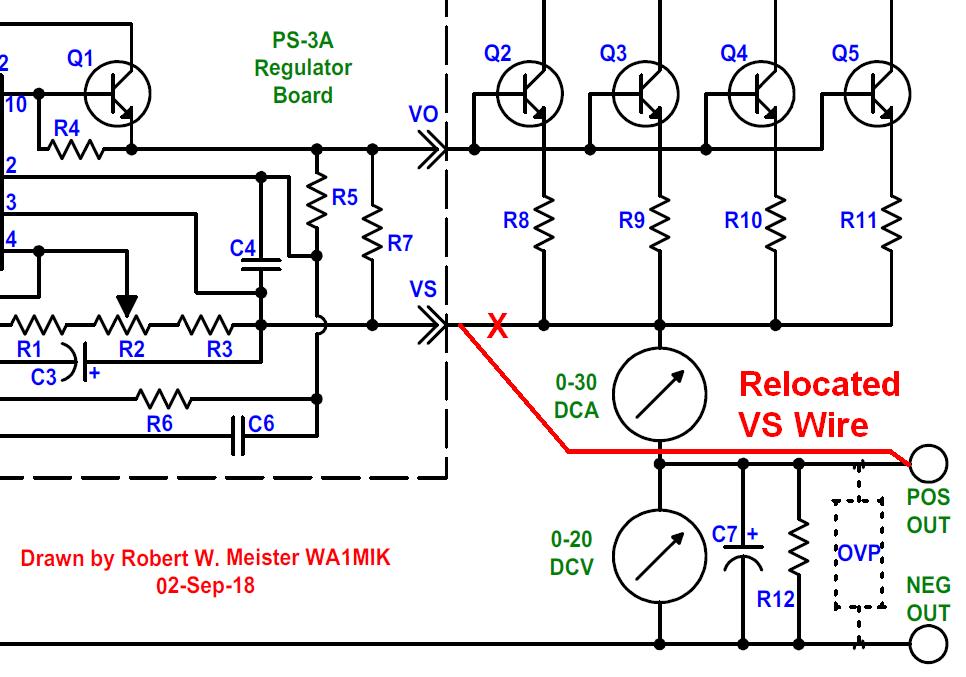
I also measured a huge voltage drop in the negative wire between the main filter capacitor and the front panel binding post with a 25A load. This wire is excessively long and actually has been spliced in my unit. It will be replaced with something heavier and taking a more direct route to the front panel binding post. The positive wire is also way longer than it has to be, however its voltage drop has been compensated for by the above modification. The "Impr. 2" column in the chart above shows the improvement with a larger, shorter negative wire.
Contact Information:
The author can be contacted at: his-callsign [ at ] comcast [ dot ] net.
Back to the top of the page
Up one level (VHFE index)
Back to Home
This page originally composed on 29-Aug-2018
Text, layout, and hand-coded HTML © Copyright 2018 and date of last update by Robert W. Meister.
This web page, this web site, the information presented in and on its pages and in these modifications and conversions is © Copyrighted 1995 and (date of last update) by Kevin Custer W3KKC and multiple originating authors. All Rights Reserved, including that of paper and web publication elsewhere.