Back to Home
By Robert W. Meister WA1MIK

|
Up one level Back to Home |
CTCSS Reverse-Burst Circuits By Robert W. Meister WA1MIK |
|
Background:
All of the commercial LMR radios offer some sort of squelch-tail elimination (STE). Some simply remove the CTCSS encode tone while keeping the transmitter keyed for as much as 500 milliseconds, so the receiver's CTCSS decoder squelches the audio circuit, due to loss of tone, before the RF carrier is lost, thus you don't hear the squelch noise burst. Others take a more active approach and reverse the phase of the CTCSS encode tone while keeping the transmitter keyed for 150-200 milliseconds, so the receiver's CTCSS decoder squelches the audio circuit before the RF carrier is lost, thus you don't hear the squelch noise burst. This method was designed when vibrating reed decoders were commonplace, and the phase reversal stopped the vibrating reed much faster than simply removing the CTCSS tone. The 180-degree phase shift is easily obtained by using a center-tapped audio transformer and selecting the signal from either end with a small relay. Newer solid-state equipment selected the signal from either the collector or the emitter of a transistor amplifier stage, achieving the same 180-degree phase shift.
Eventually Motorola determined that a 120-degree phase shift stopped the reed even faster, so they of course patented that method and still use it in all their microprocessor-controlled radios today. Other radio brands that used the 180-degree phase shift often would still produce squelch tails when used with Motorola radios that used the 120-degree phase shift, so they began to offer that as an option. Now, Motorola surprisingly offers a "Non-Standard" phase shift of 180 degrees in some of their models, so they'll be compatible with other radio brands. In order to avoid patent infringement, GE in their MASTR-II equipment, supposedly uses a 135-degree phase shift for their STE, although a few LBIs mention 225 or 235 degrees. I measured between 130 and 135 degrees on a GE MLS-2 radio.
The TIA/EIA, who publishes standards for just about everything, states in EIA-603: "CTCSS Reverse Burst is a squelch tail or noise elimination method. CTCSS Reverse Burst changes the phase of the sub-audible tone prior to the removal of the RF carrier. This serves to discharge the energy stored in the narrowband CTCSS filters at the receiver, causing the receiver audio to turn off. Thus, the CTCSS reverse burst reduces or eliminates the noise burst heard in the receiver after the end of a transmission. There are currently two formats in use. One format advances the phase of the tone phase forward by 120 degrees for 180 milliseconds at the end of the transmission prior to turning off the RF carrier. The other format advances the tone phase forward by 180 degrees for 150 milliseconds."
Note that "sub-audible" here means the tone frequency is BELOW the audible range of 300-3,400 Hz; it does not mean that the tone is NOT audible and thus can't be heard. Most radios have filters in their audio circuits to attenuate the CTCSS tones. Some are better than others. Larger loudspeakers tend to make the lower frequencies audible, and higher CTCSS tones can often be heard quite well.
It's interesting to note that even though Motorola chose 120 degrees because it caused the decoder to squelch up faster, the TIA/EIA spec allows for more time at that shift than for 180 degrees.
The CTCSS-equipped vacuum tube equipment had neither reverse burst nor any delayed carrier-only transmission, so everyone had a squelch-closing noise burst.
Individual Reverse-Burst Circuits:
I took a look at four Motorola discrete PL encode circuits, to find out how they each implemented the 120 degree phase shift: MICOR, Mitrek, Motrac, and MSR2000. I will briefly describe how each one works. There are schematic diagrams (PDFs) available for each one as well; click on the link in each paragraph below. Each PL board also has a 150 millisecond timing circuit to enable the reverse-burst and provide a secondary PTT signal to keep the transmitter generating RF during the time the reverse-burst is being sent out. I won't go into these timing circuits.
All of these boards use capacitor networks to alter the phase of the tone signal. I know that circuits involving capacitors are going to be frequency-dependent and non-linear. One goal of this experiment was to feed in my own tone signal, rather than using just the single encode reed, to see if, and by how much, the phase angle changes with frequency. Boards with a single tone signal path (Mitrek/MSR2000), rather than a differential signal path (MICOR), are easier to deal with, so I chose the Mitrek board. John W1GPO was kind enough to send me an HLN4020A Mitrek PL Encode board with a 123.0 Hz reed to play with. I've redrawn the schematic of the Mitrek reverse-burst phase shifter below for reference throughout this article.
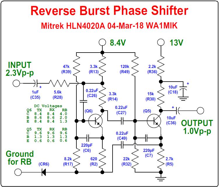
During normal tone generation (microphone PTT button pressed), Q6 is turned off and the tone passes through C35, R28, R14, C27, Q5, and C36. When the PTT button is released, Q6 is activated with a low 200-millisecond pulse at CR6, during which time the tone also passes through C26 and Q6 and the radio is now transmitting the reverse burst. At the end of this pulse, the tone-generating IC output is disabled so there's no more tone, Q6 is turned off again, and the radio stops transmitting.
Testing the Mitrek PL Encoder:
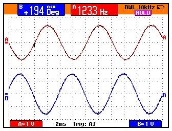
I connected my scope's "A" channel (red trace below) to the input of the phase shift circuit above (actually at pin 3 of U1, the tone-generating IC). I connected my scope's "B" channel (blue trace below) to Q5's collector. I grounded the PTT input to activate the normal (non-reverse-burst) tone audio path. The readout at the top of the screen shows that the relative phase angle between the two signals is 194 degrees. Both scope channels are set for AC-coupling to get rid of any DC voltages.
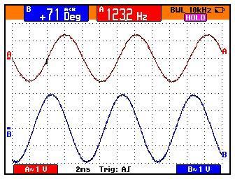
I then grounded the anode (right side) of CR6 to enable Q6, the actual phase shift transistor. The blue trace has gotten a bit bigger but now the relative phase angle between the two, as shown by the display at the top of the screen, is 71 degrees. This means the total phase shift between normal and reverse-burst is 123 degrees (194 degrees minus 71 degrees), at a tone frequency of about 123 Hz.
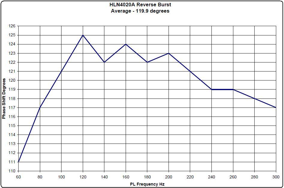
I broke the circuit apart by unsoldering the negative end of C35, and I injected my own tone from an audio oscillator into C35. I recorded the normal and shifted phase angles using tone frequencies from 60 to 300 Hz in 20 Hz steps and graphed the results. I also tried 40 Hz but the phase difference there really dropped off and was less than 90 degrees. As that's way lower than the normal CTCSS tone range, I just eliminated it from the data. The average of all the points on the graph is 119.9 degrees. Click on the graph for a larger view.
A Problem:
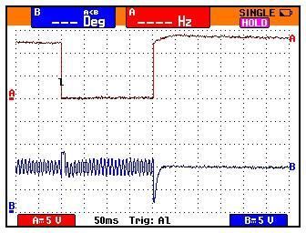
Q6 is turned on by the Reverse-Burst Enable signal (pulse) coming in via CR6. This causes the voltage on the transistor's collector to drop from 8.4V to 4.0V. This DC shift runs right through C27 and then through Q5, which actually gets turned off, and out of the PL encoder board, where it causes an audible click or pop on the signal. There's another shift when the Reverse-Burst Enable signal goes away, but by then the receiver has squelched up and the transmitter is about to be shut off, so it doesn't bother anyone. In the scope trace below, the "A" trace is the trigger and it's connected to the cathode of CR6, which comes from Q9 (visible on the Mitrek PL board PDF schematic); this is the Reverse-Burst Enable signal. The "B" trace is still connected to the collector of Q5, the tone output, which rests around 10VDC. You can see two glitches, one at each edge of the Enable pulse. The first glitch is limited in the positive direction by the available B+ voltage feeding Q5. The second glitch isn't so lucky. Also notice that the Enable pulse is 200 milliseconds wide, even though the schematic says it should only be 150.
Fixing the Glitch:
My first thought was to keep Q6 enabled all the time and just break the AC signal path, so I disconnected C26 and grounded C6 anode. This increased the normal CTCSS tone level from 1.11VAC to 1.38VAC, the amplitude of the reverse-burst tone level. I was able to connect C26 to the circuit and got just one glitch on the first attempt. Once the DC voltage across the cap had stabilized there was no more glitch. Even this glitch could be suppressed with some resistors to preset the DC voltage on the cap. A small relay could then be used to connect C26 when reverse-burst was required, but the additional parts and modification of the board forced me to abandon this method.
One way to permanently fix this issue is to have two signal paths that are always active, and use an analog audio switch to select the normal or reverse-burst path as needed. Again, additional parts and modification make this somewhat difficult.
Credits and Acknowledgements:
Schematic diagrams were taken from the appropriate Motorola manuals. Most of the radio model names and (of course) Private-Line (PL) are trademarks of Motorola, Inc.
Thanks go to John W1GPO for providing a Mitrek PL encoder board and reed.
Waveforms were captured with my Fluke 199C oscilloscope.
An Agilent E4430B signal generator created the sine waves used as input to the reverse-burst phase shift circuit.
Contact Information:
The author can be contacted at: his-callsign [ at ] comcast [ dot ] net.
This page created 08-Mar-2018.
Go to the top of this page
Up one level
Go to Home
Article text, layout, photos, and HTML © Copyright 2018 By Robert W. Meister WA1MIK
This web page, this web site, the information presented in and on its pages and in these modifications and conversions is © Copyrighted 1995 and (date of last update) by Kevin Custer W3KKC and multiple originating authors. All Rights Reserved, including that of paper and web publication elsewhere.