Back to Home
A primer on tone systems, with a
little on digital systems.
Compiled, HTML'd and Maintained by Mike Morris WA6ILQ

|
Up one level Tech Index Back to Home |
A Historical and Technical Overview of Tone Squelch Systems A primer on tone systems, with a little on digital systems. Compiled, HTML'd and Maintained by Mike Morris WA6ILQ |
|
| Lots of hams and scanner listeners use tone squelch today without really understanding it. |
NOTE: This was written in 2008. Some of the radio-model-specific or brand-specific info is dated, but the overall information is still valid.
Land Mobile Radio, or LMR (the FCC's name for commercial 2-way radio) has been around since the late 1930s. Even back when 33 MHz was considered to be the "ultra high frequencies" there were problems with channel sharing. Motorola came up with a way to get more than one Land Mobile user on the same frequency - they determined that different customers could coexist on the same frequency (called co-channel users) if they did not have to listen to each other.
In the early 1950s the geniuses in Moto R&D developed a system that added a low frequency tone to the existing transmitter audio that was present as long as the transmitter was keyed. The receiver was modified by adding a tone detector circuit to the receiver and then the receiver squelch was modified so that it wouldn't open unless the tone was there. They also modified the receiver audio circuits to strip the audio tone out of the speaker audio. The legal folks patented the idea and the technique then trademarked the term "Private Line". Sales literature of the time compared the system to the receiver having a front door lock on it, and multiple transmitters (one for each of the co-channel users) having different keys, and only the signal with the correct "key" could open the lock. Note that the entire system consisted of adding a new tone modulation circuit in the transmitter, and a new tone decoding circuit in the receiver - nothing that would actually reduce or eliminate RF interference - more on this in the "CTCSS Doesn't Fix Anything" article.
Other manufacturers, finding that the system was absolutely necessary to stay competitive, copied the idea and technology but couldn't use a trademarked term, so they came up with "Channel Guard" or "CG" from GE, "Quiet Call" from Ritron, "Quiet Channel" or "QC" from RCA, "Call Guard" from E. F. Johnson, "Quiet Tone" from Kenwood, and "Electronic Tone Squelch" or "ETS" from Canadian Marconi Company. Other manufacturers had / have other terms. Over the years, the Motorola trademark "Private Line" (or "PL") has become a generic term despite the best efforts of their marketing and legal staffs.
Once the other manufacturers came out with their systems, the Electronic Industries Association (EIA) decided to write a standard for it (RS-220) that defined the tones, tolerance, levels, and more. They needed a generic name and came up with "Continuous Tone Coded Squelch System" or "CTCSS". If you think that's a mouthful, be glad that the second choice wasn't selected: "Continuous Subaudible Tone Coded Squelch System" or "CSTCSS". Later on Moto engineering developed a digital bit stream based system and they called it "Digital Private Line", or DPL. The generic was called "Continuous Digital Coded Squelch System" or CDCSS. Many people have shortened that to "Digital Code Squelch", "Digital Coded Squelch", or "DCS" (which is a term that Yaesu / Vertex uses in their sales literature). More on digital squelch later. By the way, when "DPL" became common usage many people started using the term "TPL" when needed to specifically specify a tone PL system.
The Technical Side:
The Private Line (PL) system was first introduced in Motorola tube based radios in the early 1950s, was copied by GE, RCA, Link, Johnson, Kaar, and many others. The generic name CTCSS and the EIA RS-220 standard followed much, much later.
The overall system is designed around a specific set of low frequency tones ranging from about 65 Hz to about 250 Hz. The oldest list that I am aware of (from a November 1952 manual) is ten tones: 100.0 cps, 110.9 cps, 123.0 cps, 136.5 cps, 151.4 cps, 167.9 cps, 186.2 cps, 206.5 cps, 229.1 cps and 254.1 cps, identical to tones 1Z through 0Z in the Motorola standard tone list (and just for information, the confusing tone descriptor "0Z" ("zero-Z") came to be when the descriptor "10Z" got trimmed to 2 characters). The list of 10 tones does, however, have a note that the highest three are not recommended due to possibly inadequate filtering of the receiver audio (but they were / are used as paging tones).
Over the years the available tone list has been expanded - by 1965 Motorola was using 26 tones from 82.5 to 192.8 Hz, in the 1970s it was up to 32 tones, and by 1983 the MSF5000 station offered 42 tones in its list. These days, and depending on which industry "standard" set of tones you chose to use, there are 32, 37, 38, 41, 42, 47, 50 or 51 tones available, and the U. S. Military has their own unique tone of 150.0 Hz that doesn't appear on any list of standard Land Mobile tones. This 150.0 Hz tone is the standard CTCSS tone for all military units belonging to NATO, Canadian Armed Forces, the UK Ministry of Defence, Australia and New Zealand. And most military radios are still using the 1960s definition of wideband modulation: ±15 kHz for the voice deviation level plus ±3 kHz for CTCSS deviation.
No matter what tone you use, the EIA / TIA-603 international standard for Land Mobile Radio performance calls for about 12% of total tone deviation. When looking at a ±5 kHz deviation channel thats about ±600 Hz, and on a ±2.5 kHz channel (common on 900 MHz) the specification is half of that. Most public safety grade commercial radios I've seen run about ±600 Hz and a few run as high as ±800 Hz. Very few that I've seen run as little as ±500 Hz deviation. Typical amateur radios from Alinco, Icom, Kenwood and Yaesu run anything from ±500 Hz to ±1 kHz. I've seen quality commerical radios that reliably decoded only ±100 Hz of PL deviation, and their receive audio filters were so good that the hum was still inaudible at ±1 kHz PL deviation. So why run ±600 Hz deviation if something less will do? Reliability.
From an email to repeater-builder:
The fact of the matter is that if the CTCSS output is clean (i.e. no distortion) then ±600 to ±700 Hz deviation is very rarely audible. Every time I've tried lower deviation I lose decode ability in noisy areas, especially if there is any QRM or QRN (even power line noise) around. Changing channels to a different repeater at the same site running the normal amount of deviation resulted in a working system. There is a very good reason why my personal standard on CTCSS deviation is between ±600 and ±700 Hz: It just plain works ! And the increased encode level adds robustness - it has enough headroom that it won't drop out when the signal gets a little noisy! Yes, ±200 to 400 Hz of deviation works most of the time, but why ask for an intermittent system? Do you really want a flaky decoder?
For fast operation the encode tones must be a clean sine wave and the tone frequency tolerance is very tight. ANY frequency error in the tone encoder or decoder, or distortion in the tone encoder output will slow the decoder down, and can sometimes prevent it from decoding at all (and thereby preventing the receiver from ever opening the squelch). And that means that the frequency accuracy and stability requirements of the receiver and transmitter is much tighter - you can get away with a little on carrier squelch systems, but any tone system requires much tighter frequency control - any off-channel error adds a lot more audio distortion than you would think.
CTCSS (no matter what the manufacturer / trademarked name) is a continuous and subaudible tone. In fact, "sub" means "below", as in this case "lower than 300 Hz". That doesn't mean that it's INaudible, meaning "not hearable". That's a big difference, and the tone was audible in cheaper receivers that didn't have a good high pass audio filter. Users of receivers with poorly designed (or otherwise inadequate) audio filters (or even no filter at all) frequently mistake the tone for a power supply hum. When the system is properly implemented it is almost impossible to hear with the un-aided ear.
The circuitry used in the CTCSS system, when you actually sat down and analyzed it was pretty simple and was made up of four, sometimes five, separate sections, plus more attention was paid to RF frequency accuracy:
For years the component that determined the tone was a single plug-in unit. Motorola, GE and RCA used plug in vibrating reeds, E. F. Johnson and others used plug in electronic modules. Since the average radio only had one tone socket, changing the tone in any given radio was as simple as unplugging and plugging in a tone reed or an electronic module (or using a relay (or some relays) to switch between two (or more) plug-in reeds or modules). This held true up to the days of programmable radios.
Radios in the late 1950s and throughout the 1960s usually could be had in one, two and four RF frequencies, but 99% of the time only one tone frequency, if the radio had tone at all. As such it was not unusual to have most agencies in an area (especially in rural areas) to use a common tone throughout the area. When the California Highway Patrol wrote the RFQ (Request for Quote) specifications for a new statewide fleet of radios in 1966 the specification for the patrol mobile included four frequencies of transmit, two frequencies of receive, and dual PL tones (both encode and decode). Motorola didn't have any problem with a 4+2 configuration, but they didn't have any standard models that would do dual PL. They ended up taking an existing 4-frequency design (the LLT series Motran) and modified it to meet the specs - they added a second set of reed sockets and reeds, and the selection of encode and decode tones was slaved to the RF frequency selector switch by way of a diode matrix. As far as I can tell this was the first factory radio that was capable of more then one tone (at that point hams and some commercial two-way radio shops had been modifying radios for multiple tones for years). My personal Motracs had relays that selected 4 different encode tones... On the older ones that used copper banannas I switched the reed coils, on the later ones that used mini-reeds I drove the primary side of all of the reeds (wired in series), and then I used relay contacts to select the secondary side.
Early Technology:
When it was invented in the early 1950s the tone was generated and detected with the only technology of the day that was frequency stable across a wide temperature range and in a high vibration mobile environment: vibrating reeds - one-legged tuning forks in a protective plug-in housing. The first implementation in the Motorola tube based base and mobile radios had large copper-encased encoder (the Vibrasender™) and decode (the Vibrasponder™) reeds.
From the 1952 Motorola Manual mentioned above:The P-series reeds did not last long due to internal mechanical problems. The TU-217 Vibrasender and TU333 Vibrasponder directly replaced them and were a standard item for over a decade.
"The Vibrasender is referenced as a P-8511 and is packaged as a small plug-in unit, approximately 2 inches wide by 3 3⁄8 inches long by 1 inch high."
...and...
"The P8611 Vibrasender is similar to the P-8511 unit except for the internal mounting of the tuning fork. The P-8611 is packaged as a small plug-in unit, approximately 2 inches deep by 3 3⁄4 inches wide x 1 inch high."
The Vibrasponder is referenced in the manual as a P-7810.
The Vibrasponders had four pins: two went to the drive coil and two went to a pair of internal contacts that closed and opened with each cycle when the reed vibrated at the proper frequency - if you had a 100 Hz reed you had 200 pulses per second from the contacts. An integrator circuit filtered this pulse train contact closure into a DC voltage and the developed voltage turned on an audio gating circuit that allowed the audio to pass to the speaker.
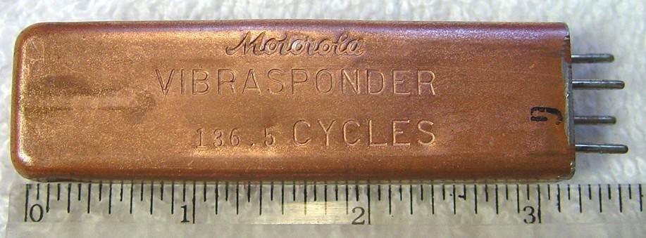
A side view of the TU333 Vibrasponder
Except for the Vibrasender name stamped in the side of the unit,
the TU217 Vibrasender was packaged identically.
The package is 1⁄2 inch (1.25cm) high, 7⁄8 inch (2.2cm) wide, 3 1⁄8 inches (7.9cm) of body length, 3 1⁄2 inches (8.9cm) including the pins. One common name for the reed package was the "copper banana". Some paging tone reeds were made in a package that was the same height and width, but about 2⁄3 the length. I once worked on a paging base station (all tubes) that had a forest of copper reeds... about 40 of them that were selected by a forest of plug-in relays.
The Vibrasender encode reed used the same housing, connector and socket. It had two pins for the drive coil and an internal jumper from the third pin to the fourth pin. When plugged into the circuit, the jumper would activate the oscillator and the coil would be energized such that it resonated and developed the desired tone.
You couldn't exchange the copper Sponders and Senders in a stock circuit due to the second pair of pins being shorted in the Sender but not in the Sponder. You could put a short across the encoder enable pins on the socket and use a Sponder in a Sender socket (and on my first PL mobile that's just what I did until I found a 127.3 Hz Sender). Using a Sender in a receiver would put the jumper in place of the contacts, and cause the squelch to be open all the time, thinking it was receiving a PL signal. So you were screwed if you swapped a Sender into a Sponder socket, but it was a fun trick to pull on the new shop tech. My first multi-tone mobile was made by slaving a relay to the frequency select line in the radio and using the contacts to select one or the other Vibrasender coil. I had 131.8 Hz on one RF frequency and 127.3 Hz on a second frequency. Later on a second relay allowed 100 Hz on a third frequency.
The older copper reeds had different vibrating characteristics, i.e. a "Sender" without the contacts produced a smoother output waveform and took longer to start or stop vibrating. The "Sponder" didn't care about the waveform and it was often overdriven just so the contacts would open the squelch as quickly as possible. They also were weighted such that the reverse-burst would stop them without causing them to start decoding the reverse phase (before the transmitter shut off). More on that later.
The big copper reeds worked and worked pretty well, but they had their problems. One was that on a rough or washboard road you could get a false decode if the contacts in the Sponder closed at a repetitive rate - in some cases even a gravel road or rough pavement would do. Another was that if the audio coupling cap was leaky the DC from the reed driver could "burn" the fragile contacts and kill the functionality of the decode reed (essentially not repairable). And the radios were getting smaller, and the copper reeds were just too big.
Enter Bramco Corporation of Piqua, Ohio, and their contactless mini-reed.
Motorola needed to add PL to the design of their handhelds and had a problem... there was no room for the "copper banana" reed. So they went to the reed experts. Bramco Corporation took the copper banana and a clean sheet of paper and did a total redesign. Then THEY (Bramco) patented the mini-reed. The new design was the size of the KLN6210 reed in the photo below), and had no contacts to get dirty or burn. Internally the Bramco reed was a tiny one-legged tuning fork with a magnet mounted crosswise in the end of the tine. The magnet moved inside two tiny coils and formed a very precise and very stable frequency resonant transformer. A clever circuit design allowed the single reed to work as both an encode and as a decode reed if needed, like in a handheld. Both Motorola and GE marketed the Bramco design for years and years under a wide variety of model numbers. Bramco was eventually sold and became the Bramco Controls Division of Ledex Inc. Bramco published several books on tone control, their 1966 book, "Control Techniques with Resonant Reed Relays" was a bible of the radio controlled model community. I had a copy, loaned it out, and the borrower evaporated along with my book.
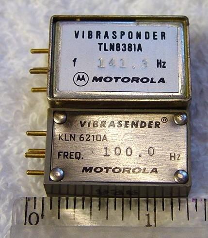
A side view of the Bramco-manufactured mini-reeds. The top reed is
a MICOR decode reed, the lower reed is a standard sized mini-reed.
The TLN8381 MICOR decode reed was the only one to be made in the
oversize package.
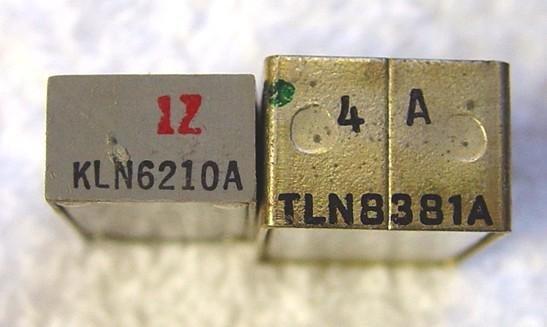
A top view of the small reeds. The left reed is a standard sized
mini-reed, the right reed is a MICOR decode reed.
The Bramco mini-reed specifications were:
Frequency Range: 66 to 3000 Hz (CTCSS used 67-251 Hz, the higher frequencies
were used as paging tones)
Temperature Stability: Frequency varies less than 0.002% per degree C
Impedance: approximately 1000 ohms at resonance (input and output)
(but different model numbers used impedances from 500 ohms
to 5 K ohms).
Drive Level: 66-300 Hz - 0.05 to 0.2 VRMS
Drive Level: 300-3000 Hz - 0.10 to 0.3 VRMS
Encoder Freq. Tolerance +/- 0.3% (- 40 to 85 degrees C)
Dimensions (Height, Width, Length of body, Length with pins) in inches:
Standard small reed (the KLN6210A in the photo): 3/8, 5/8, 1-1/8, 1-1/4 inches
The large TLN8381A decode reed package: 1/2, 3/4, 1-1/8, 1-1/4 inches
Many commercial 2-way radio systems needed "split tones" - where the encode tone was different than the decode tone, so the mini-reed was made in both Sender and Sponder designs. Split tones were difficult in hand-helds due to size and space, but Bramco had an answer to that as well... a half-size reed.
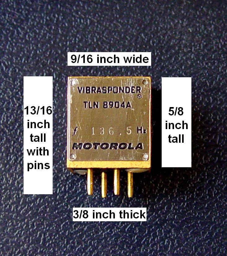
I've seen the TLN8904A "sugar cube" reed (yes, that is what it was called) in several handhelds - it was half the length of the KLN6210 above. The first time I saw them was in a special products PL board made for a handheld. The board held two reeds, and it allowed either two different tones on the six frequencies, selectable by a diode matrix, or a different configuration of the board allowed split encode / decode tones. The sugar cube reed worked on a different principle: instead of a one-legged tuning fork with a magnet in the end, it used a taut band with an S-shaped weight mounted at right angles in the middle of the band, with tiny magnets at each end of the S-shaped weight, and coils surrounding the magnets. As the primary coil was driven the S-shaped piece twisted the taut band back and forth and created the sine wave in the secondary coil - that action formed the resonant transformer.
Bob WA1MIK reports "I had a Standard SR-C146 VHF handheld in the mid 1970s. I also bought the TN3 "Private Channel" encode / decode board, which used one of those "sugar cube" reeds, TLN8904A. It worked well until one day I dropped the radio, bending the case and causing the tone to cease functioning. Having nothing to lose, I filed off the heads of the rivets, opened the reed, determined how it operated, and noticed that the two swing arms with weights were extended at different lengths. I bent one to where it seemed to center the magnet in the coil opening, and the reed started working again." He dug out that old radio and snapped a photo with dimensions.
The use of plug-in reeds (large and small) continued through the 1950s, the 1960s 1970s and into the 1980s: the "Research Line" (all tube), Motrac (hybrid tube and transistor), Motran (all transistor), MICOR (all transistor), Mitrek, and other product lines of the period. At some point the production was switched from a metal case for the reed(s) to a plastic case to save weight and lower the cost. In addition many specially packaged reeds were developed to fit them into unique spaces in specific radios (especially handhelds). Some reeds were wide and very thin, or very long and short, or other custom shapes. (Anyone want to contribute some photos?)
Roll forward to the current era and the ham radio manufacturers seem to have settled on "tone" as the term to use in the operators manual to describe the encode side and "tone squelch" for the decode side. Most of the amateur VHF and UHF equipment manufactured since 1990 has at least encode capability (standard or optional) and many have decode capability (standard or optional). If it isn't built in, it is simply a plug in optional circuit board. Most radios oriented towards amateur radio do not offer split tones. Aftermarket encoders and encoder/decoders (such as those from Communications Specialists, better known as Com-Spec) can be added to almost any radio, as they are smaller than a large format postage stamp. And it's not that hard to build your own tone encoder.
Applications of CTCSS:
The initial design specs at Moto was to enable multiple user groups share a simplex dispatch channel - maybe have the county dogcatcher share with the county road crews and the school busses. But the first few years of reality outpaced anything that was envisioned at the designer's workbench.
In the commercial two-way radio world, there is what is called a "community repeater". This is a regular repeater with a "tone panel" attached. Picture a number of tone decoders on the receiver, each linked to a separate tone encoder on the transmitter. User group "A" (perhaps a diaper service) uses 67 Hz, User group "B" (perhaps a landscaping service) uses 82.5 Hz, user group "C" (perhaps a drain cleaning service) uses 94.7 Hz, user group "D" (the roofing company) uses 103.5 Hz, and so forth. Note that in the example above there are only four co-channel user groups. In dense two-way radio environments the number of groups can be higher - sometimes much higher. As long as nobody "hogs" the channel and each waits their turn, each user group can use the same repeater without hearing the transmissions of other groups (but a receiver without a tone decoder, or a disabled tone decoder, would hear all transmissions from all groups). The tone panels also remove (filter out of the receiver audio) the incoming tone and replace it with an internally generated tone (into the transmitter) so that the outgoing signal has a clean tone. Communications Specialists (Com-Spec), Connect Systems, Vega and Zetron are just four manufacturers of tone panels, there are and have been others.
The use of a different CTCSS tone for each group of users on a channel allows several different groups of users to be on one frequency without hearing each other. They will, however, cause interference to each other if they just key down and talk. Another use of the tone is to allow several different repeaters to share the same RF frequency - just use different tone frequencies. And there are tricks that can be used there - many years ago I did some work for an excavating company that used two community repeaters on the same RF channel with overlapping coverage areas, and they bought time on both repeaters. Their radios had channel 1 and channel 2 set up with the same RF frequencies, different encode tones and the same decode tone. They might encode, for example, 127.3 on channel 1, 131.8 on channel 2, and decode 131.8 on both. Repeater one is on the south end of town and listens for 127.3 and talks with 131.8, and repeater two is on the north end and listens and talks on 131.8.... If a user needs to call his dispatcher he just selects the "north" repeater or the "south" repeater depending on where he is, and calls in, i.e. "Dispatch from truck nineteen on north".
In a commercial mobile installation, the mobile microphone hanger is wired into the tone decoder and when the microphone is hung up, the decoder is turned on, thus muting the receiver. When the user picks up the microphone, the decoder is disabled, the receiver goes into carrier squelch mode and the user hears any activity on the channel. If nothing is heard, the call is made and every radio using that tone unsquelches. If, on the other hand, the channel is in use, they are supposed to monitor until the traffic clears and then make their call. Base station microphones have a "monitor" button next to the PTT button to disable the decoder (and most are mechanically interlocked so that you can't PTT without holding down the monitor button first), forcing the operator to check for traffic first. Most commercial handheld radios have a monitor button, usually located near the PTT bar for the same purpose. Some radios have a feature called "Busy Channel Lockout", which will not allow the user to transmit as long as the squelcy is open (i.e. the radio is receiving another signal).
The same microphone clip trick is still used today, but some other techniques are used to make it simpler - see this article on hangup methods. Another manufacturer put a magnet in the clip and a reed switch inside the microphone case.
Some police dispatch systems mix patrol, vice, detectives, and more all on the same channel. Rather than have everyone listening to everyone, the each group of mobile users hides behind their tone decoder and does not hear anyone else unless they lift their microphone out of the clip. Then they get to wait for an open channel.
Modern amateur radios do not have this microphone hanger feature since the CTCSS system is used for more than to allow several fleets of radios to operate on the same frequency. Amateur CTCSS has multiple different purposes - and repeater selection is just one of them. Another is to allow users to restrict what they want to listen to - if you have two repeaters with some coverage overlap the system transmitters can send a tone, and the users can use tone decode to prevent hearing the other system. A third use is for repeater control - years ago I saw one system where bursts of different tones were used to control various functions - the system repeated users with a 103.5 Hz tone, but a 1 second burst of 114.8 Hz took the phone off hook, and a second burst hung it up. A different system (that one was a carrier squelch system) used four PL tones to enable or disable the system and the backup generator at the repeater site: call the tones A, B, C and D. One second of A followed by one second of C was repeater system on, A then D was system off. B then C was emergency generator on, B then D was generator off. A then B set the generator to automatic mode. When the generator was running the system encoded 67.0 Hz on the output.
Some radios may have a "monitor" button, which will momentarily open the squelch. Other amateur mobile users have to manually turn off the tone to monitor the frequency in the carrier squelch mode. Some folks program adjacent memory positions (channels) so that bumping the channel button up one position switches to carrier squelch mode and bumping the channel button down goes back to CTCSS decode mode.
From a posting on the repeater-builder mailing list:
One cute trick that has been used since the 1970s was / is
called "PL Paging" (it's called that since it has been around
since long before the term CTCSS was established). Picture a repeater
that may or may not require a tone to key it up, but the system transmitter
does not use a tone encoder. The "PL Paging" method adds
a tone encoder to the system transmitter, but it is normally off. The repeater
system operates as usual. All that is needed is a DTMF decoder than can
pull in a relay, and that functionality is in almost any modern repeater
controller. Simply set it up so that when a user sends the proper DTMF
digit (or sequence of digits) a relay closes and enables the system
transmitter PL encoder - but that relay drops out when the carrier on
the input goes away. The PL Paging feature is available to anyone
that wants to use it - all they need is a radio with switchable PL decode.
Let's say that the DTMF trigger sequence for the PL Paging is 757. An example of how it is used goes like this... Picture this conversation on the repeater:
Tom: Hey, does anybody have a way to measure the actual temperature of a power supply heat sink?
Dick: I think Ralph has one of those non-contact laser IR thermometers in his tool box. Hey Ralph, are you listening?
(15-20 second pause)
WB6SOX, are you listening?
(15-20 second pause)
Dick: Let me try to raise him - (DTMF 757 is heard) Paging WB6SOX
(15-20 second pause)
Ralph: WB6SOX here, someone pulling my chain?
What happened was that Ralph had his radio in tone decode mode and
was not hearing any of the conversation on the repeater. When Dick paged
him all he heard was his speaker all of a sudden emit the trailing end
of the second DTMF 7 and the "Paging WB6SOX" message,
then it went silent again.
(the trailing end of any DTMF digit makes a good "alert tone").
Note that Ralph does not have a DTMF decoder - he has a plain-jane radio that happens to have the standard tone decode feature. All the hard work is done in the repeater.
The text above mentions a DTMF decoder pulling in a relay, because that's how the first one was implemented - a Speedcall brand DTMF horn-honker decoder (that had been retired from IMTS service) drove one coil of a two-coil latching relay. The COR pulsed the other coil. The contacts operated the tone encoder. These days it can all be implemented in the repeater controller - and while any modern controller can do PL Paging, the Scom 7K (no longer in production) actually has a tone encoder audio gate built into it and you'd think it was designed just for the job. It also has 6 digital outputs that are designed to be wired to the tone control leads of a TS-32 or TS-64 (or any other similar tone encoder).
From another email to repeater-builder:
...most commercial and public-safety repeaters and base stations
automatically strip (or just don't encode) the tone whenever the station
ID is transmitted. The users of such systems would quickly find a Morse
code ID every N number of minutes to be very annoying. All of my repeaters
(no matter what service) strip the encode tone during ID, and nobody ever
hears an ID. Many of the Hams who use my repeaters have commercial-quality
radios with full-time PL decode, and they are very happy to not hear the
ID or any squelch crashes.
A Few Notes on Tones and Tone Selection:
Summary: The above concerns collectively cause some system engineers to restrict the tone selection to the 10 tones from 127.3 Hz to 173.8 Hz - as this range balances fast decoding with keeping the tones out of the audible part of the receive audio. If CDCSS will ever be used on the channel then that lowers the selection to 8 tones as that eliminates both 131.8 Hz and 136.5 Hz. If your system users have radios with better quality transmit audio filters (to keep the speech out of the encoder) and better receiver audio filters (to keep the hum out of the speaker) then you can skip over 179.9 Hz and raise the upper end to 186.2 Hz or even 192.8 Hz.Occasionally someone tries encoding two tones simultaneously to open the tone squelch on two groups of radios on the same channel. If you are VERY careful with your levels, do not use harmonically related or intermodulation-related tones, and use reed-based decoders it CAN work. But modern radios with microprocessor-based decoders have totally ruined that trick, as this email to repeater-builder shows:
...another commonly attempted practice is mixing two CTCSS encoder tones, say one is the main user community of our 2m repeater (i.e. always on), and another only during some type of emergency alert. One of the local repeaters does this for Aircraft ELT alerts from receivers on 121.5 MHz and 243.0 MHz. The folks who did it understood that it would be problematic both to get the levels right, and also for the user radios, and picked tones that weren't harmonically related, etc. It worked well with many ham rigs built in the 80's, but some just didn't. Those and most modern rigs obviously don't do tone detection the same way older rigs did, and they MUTE when both tones are present. Differences in new tone decoders (I assume DSP-based?) mean that mixing multiple tones doesn't work as well as it once may have (it was never GREAT, but it did work, but now it's just broken, which is completely understandable.)
Political Considerations, Open, Closed, and Private Systems:
To quote the Bill Pasternak WA6ITF writeup in the 1980s book on repeaters, "PL does NOT make a repeater closed or private!"
To quote another friend of mine, "'Private Line' has nothing to do with operational status of a system, being open or closed. PL does not mean 'please leave'".
Thirty to forty years ago adding a tone encoder to a radio was a technical challenge - making it frequency and amplitude stable across the peak of summer to the depth of winter temperatures, making it fit into the leftover space in the handheld or mobile, and making it modulate cleanly. Today, it's a menu selection.
The classification of an amateur repeater (in any list or directory) is purely the system owner's choice. In many areas there are three choices: open, closed (i.e. club), and private. Open is just that - any licensed ham can use it, closed requires you to join the group and pay dues (but membership is open to anyone with a ham license and a fat wallet), and private allows the system owner to pick and chose who uses the system. Some areas have additional, sometimes informal, categories: "Open system but private remote base and autopatch" is one, "Private but Friendly" is another. I know a few system owners that run their repeater(s) as Open, but list their systems in the directory as Private just to preserve their legal option of de-inviting any troublemakers. Yes, you can make that stick.
However, as you can see from the above, CTCSS is purely a technical system; the repeater access classification depends on the wishes of the system owner (or trustee) and the co-operation of the local coordinating council. An open repeater can use carrier squelch or CTCSS decode, a closed repeater can use carrier squelch or CTCSS decode, a private repeater can use carrier squelch or CTCSS decode. In all cases, it's politics, not technology. Setting a tone encoder to the proper frequency is a minor inconvenience when you consider how many potential problems it can eliminate. Most coordinating groups strongly recommend the use of tone squelch on repeater receivers. Some areas mandate tone squelch as part of an individual coordination grant due to such situations as proximity to a co-channel repeater, or in an area where band openings frequently aggravate co-channel interference problems.
Some open repeaters use a CTCSS decoder to prevent key-ups by users of other repeaters on the same channel. Many of these announce the tone frequency on the voice IDer (You might hear "Monitoring one-forty-six-point-two-two with eighty-two-point-five Hertz" on a 146.82 MHz repeater), as well as list the tone frequency in the Repeater Directory. Traveling hams really appreciate the voice announcement, especially on an odd-split repeater. Some closed repeaters use CTCSS or the digital version to limit access to only the club members. Some private systems do the same. Some private systems run a strange offset in addition to tone or digital squelch. Some systems list one PL tone in the directory, and the members use a different tone (that enables the toys like the patch or remote base). If you are going to use your mobile rig as a temporary cross-band repeater (another feature found in many radios today), it's a good idea to use a tone decoder on the receiver. This will limit access to only you and those you've chosen to operate the system.
Some folks try to use weird nonstandard tones to resolve people problems. Sure, the receiver won't unsquelch if it is requiring a weird tone and the individual only has the standard tones, but he can still sit there and transmit on the channel causing a heterodyne or capturing / blocking the receiver, so what real security (or increase in usability) have you really gained? And what prevents a determined and resourceful person from listening to your input frequency with an OptoElectronics tone grabber (or another similar piece of equipment) and finding your weird magic tone (or tone sequence)? It takes maybe 3 to 5 seconds of signal, and then it's no longer a secret. And the Tone Grabber unit is simply a portable luxury as a carrier squelch receiver plugged into the computer sound card and a audio spectrum analyzer (sometimes called a "waterfall display") program is all they really need.
In some geographic areas specific tones (such as 100.0 Hz) are indicators of open repeaters (likewise DCS / DPL code 411). No, we are not saying that 100 Hz (and DCS 411) is an open tone (code) in YOUR area, you need to check the open repeater list published by your local coordination group (or the ARRL repeater directory - the League gets the information it publishes from the local coordinators).
Just remember, the requirement to use a subaudible tone or a DCS code to access a repeater does NOT mean it is a closed or private repeater. Adding a tone or a DCS code to a repeater receiver does NOT change the status of a system.
"Talk Off" and other problems:
If you are going to build a repeater that will be used by a large number of users you will naturally want to use a high performance / high quality radio as the repeater itself. Some of these radios, like the GE MASTR II and the Motorola MICOR were produced in an era where tone was an option. The builder may chose to chase down the optional parts or may chose to use an aftermarket / add-on tone board. Personally I prefer to chase down the proper parts from the original manufacturers - fortunately the MASTR II and MICOR stations used the same tone parts as the mobiles of that era and the parts can be readily found.
Some lower quality mobile and handheld radios have very poor CTCSS performance and have distorted encoders, slow-to-open or slow-to-close decoders, audio filters that don't remove the higher tones, audio filters that add distortion to the receiver audio, etc. Sometimes you can abandon the internal CTCSS sections (encoder, decoder or both) in a mobile and and fit a Com-Spec board inside, other times you just have to use a different radio.
As an example of extreme problems, some Alinco models, including the DR-135, DR-235 and DR-435 mobiles, use a tone decoder that is (in)famous for having the speaker continue to talk for as much as two full seconds after the incoming tone goes away (one eHam review says FOUR seconds). Or how about the Yaesu VX-1 - when you turn on the tone decoder the radio goes into a mode where once the tone decoder opens the squelch it stays open - forever - until the carrier squelch closes. In other words, it behaves like a single-tone decoder (also known as a tone burst decoder) instead of a CTCSS decoder.
And then there are situations where the audio just seems to mute when
someone close talks the microphone. It's because the tone decoder stops
decoding and the receiver audio mutes - just like it's supposed to.
Here's why, from an email to repeater-builder:
The current batch of two-band and dual-band radios from one Japanese manufacturer is notorious for having CTCSS encode problems.
It's because of several outright design screwups:
- The designer(s) strive to get very flat, wide-band microphone audio through the entire transmit audio system, starting with the microphone element itself. They seem to think that broadcast quality audio should come out of their equipment. I don't agree. Time after time it's been proven that the optimum audio communications range is from (about) 300 Hz to (about) 4000 Hz!
- The designer(s) introduce the CTCSS tone at a fixed (non-adjustable) level before the deviation control.
- There is ZERO high-pass filtering of the mike audio so any low-frequency audio picked up by the mike mixes with the encoded CTCSS tone. The decoder at the other end (in the repeater) expects to see just the CTCSS tone and gets confused by the audio interference - just as if it was a jamming signal.
Note that Motorola (among others) resolved each of the above situations over 50 years ago, and the technology is not secret:This same Japanese manufacturer has had good, even excellent, designs in prior products, what happened ? Did someone retire ? Is there no peer review of new equipment designs ?
- They start with the microphone - it's tailored for the optimum audio communications range from (about) 300 Hz to (about) 4000 Hz. The microphones are designed to roll off the lowest and highest frequencies, plus the lowest frequencies are additionally and purposely filtered by the use of small-value coupling caps in the mic audio stages. It's not supposed to be broadcast-quality. You want all the audio energy in the voice band so the words come through in a noisy situation.
- The CTCSS feeds both the VCO and the reference oscillator separately so the CTCSS modulation level and quality can be maintained regardless of voice audio. Better designs allow the transmitted CTCSS tone level to be adjusted independently of the voice level to meet the specification.
- The microphone and the audio circuits have some high-pass filtering in them, and the CTCSS tone is injected after all limiting, pre-emphasis, and splatter filtering, so any distortion in the mike audio (like someone shouting into the microphone) doesn't have any effect on the CTCSS tone frequency range or the transmitted tone level.
Or how about this problem, from another email to repeater-builder, from a different originator, but interestingly enough with the same brand of Japanese radio mentioned above:
A friend had a vehicle with tires that had a rather aggressive tread design. Whenever he drove at a certain speed, or over a metal-grate bridge, the growl from those tires, and vibration within the vehicle itself, would be picked up by the mobile microphone and severely interfere with the radio's internally-generated CTCSS tone. This audio mix would cause the repeater receiver to close the squelch on a perfectly quiet RF signal just because the repeater receiver's CTCSS decoder got confused by the impure signal and the interference in the sub-audible tone band. Yes, he could not use the repeater at certain driving speeds! Apparently that model of radio had NO sub-audible audio band filtering in the microphone circuit, it seemed like it passed anything that came into the microphone onto the modulator regardless of audio frequency.
Sometimes tone problems aren't really tone problems - they can be caused by hardware problems elsewhere, or even design problems in a different part of the radio.
One example: a friends 1970s Ford F250 pickup truck had a strange problem with a Kenwood TM-721 mobile... The design of the radio had very poor filtering on the DC power to the exciter, and coupled with one bad diode in the alternator resulted in alternator whine modulating the transmitter (note that this is not limited to older Fords, any alternator can have a bad diode, and the vehicle owner might never realize it if he never went over 2/3 load on the alternator). The combination of a bad diode and poor DC filtering caused a weird symptom... the alternator whine at certain engine speeds would mix with the CTCSS encoder and cause repeater dropouts. The whine frequency naturally varied with engine speed and manifested as a varing audio tone from about 500 Hz to as high as 3 kHz, so it shouldn't have caused any problem. However there were some "magic" frequencies that would... You could hear him talking on the repeater with a full quieting signal, and as he accelerated from a stop, or decelerated and braked to a stop the whine pitch would vary and at two or three points of whine frequency you'd hear the repeater receiver mute (i.e. lose CTCSS decode) and a few moments later unmute as the decoder reacquired the tone. The problem was solved by swapping radios in the F-250 (which was later sold and went to Montana), and the radio was given to a new ham (who used it as a base station). The proper fix would have been to replace the bad alternator diode, or have the designer use a larger capacitor in the exciter VCO and modulator DC power filtering, or (preferrably) both.
Another example: A slightly mis-tuned receiver I.F. transformer or a slightly mis-adjusted discriminator can cause a lopsided response in the receiver that would not be objectionable in a carrier squelch system, but would cause enough distortion that a CTCSS decoder would have a very hard time decoding. And the misdajustment could be an accident on the production line, or even just an aged capacitor in the wrong place in the circuit. The symptom would that the radio would work fine in carrier squelch receive, but when placed in tone decode would be slow to unmute the audio, or just not decode at all. A ham with limited test equipment might suspect the decoder, and even replace it, not realizing that the decoder was just fine, and never suspect that his receiver I.F. or discriminator was misaligned or misadjusted.
Other radios have other problems due to outright bad design, as this email to repeater-builder (from yet another originator) shows:
...Can anyone suggest ways to reduce CTCSS dropout when someone is talking loud on a radio? The user radios are set up for 600 Hz of CTCSS encode and a 1 kHz tone gives 3 kHz modulation, but I have one user that talks louder than the other users and he seems to breakup all the time where other users seem to have no problems. Could the problem be more tied up with the repeater receiver?
The reply was:
...I suspect that the problem is "talk off" caused by overdeviation of the mike audio. When the CTCSS tone is mixed with the mike audio prior to the deviation limiter stage, an excessive voice signal will be hard limited along with the CTCSS tone, causing a distorted signal. Once the CTCSS tone is distorted past the point where the tone decoder can recover the tone the decoder shuts off and the audio mutes just like it is designed to. This problem occurs quite often in low-end commercial equipment and amateur-grade equipment, since the manufacturers often have very "hot" tone deviation that is set with a fixed resistor rather than adjustable as in the better commercial-grade radios. Alinco, Icom, and Yaesu handhelds and mobiles seem to have this problem all the time. Every Alinco handheld I've tested has a fresh-out-of-the-box PL deviation above 1 kHz, and a few samples were up to 1.5 kHz (almost three times the necessary amount). Needless to say, a tone deviation of 1.5 kHz doesn't leave much room for voice deviation, and all it takes is a loud talker to cause the limiter to "squash" the modulating signal (as it should) and distort the CTCSS tone enough for the repeater tone decoder to drop. It's not easy, but I have padded the CTCSS tone circuit in several Alinco and Yaesu radios to reduce the level to about 550 Hz to 600 Hz deviation, and that completely cures the problem. The tone decoders in many modern repeater receivers can detect a tone as low as 100 Hz deviation, so setting the tone to about 600 Hz should work fine.Of course, there are the "diddle-stick artists" or "golden screwdriver jockeys" who assume the production line techs at the manufacturer screwed up and set the deviation too low and can't resist cranking up the mike level so that they will "sound better" (they think) and therefore they make the problem worse. In order to stay within a 5 KHz deviation / 16K0F3E emission envelope (i.e. stay within the receiver bandwidth), the total deviation should be limited to around 4.8 to 4.9 kHz maximum. Most commercial-grade radios automagically reduce the voice level when a tone is added, but many low-end radios aren't that smart. If the total deviation is limited to, say, 4.8 kHz, but a tone is not used, the voice deviation will sound a little softer. I suspect that the diddle-stick artist cranks up the gain to offset that lower level.
The fact that only certain users have the problem strongly points to the individual user radios, rather than the repeater. Another thing to look at is the RF frequency of the user radios - please make sure that the problem radios are exactly on frequency - any signals that are off-frequency will appear to be distorted, and the additional distortion will only make the tone decode problem worse. And make sure that the users are talking across the face of the microphone, not into it.
I suggest that you verify the CTCSS deviation on each transmitter is near 600 Hz, and ensure that the deviation limiter is set no higher than 4.9 kHz or a hair less, including the CTCSS. See if that reduces or eliminates the talk-off problems. The radio service manual should have a procedure for mike gain and limiter setting, which should be followed.
Another discussion revolved around complaints of talk-off of a GE MASTR II repeater. The response was:
CTCSS talk-off is a fairly common issue with amateur radios that have high voice to ctcss ratios from the factory. typically 6 kHz voice and under 500 Hz CTCSS deviation is not uncommon but wreaks havoc on many quality CTCSS decoders... While you can use a lower frequency tone (i.e. further from the voice band) or mod the filter skirts on the decoder the proper fix is to reset the mobiles voice-to-tone ratios - something that should have been done on the factory production line. One thing you could try is a different CTCSS decoder - a later design like a TS64 might do better, or might not.
What the MASTR II station is looking for is more like ±4.9 kHz deviation including 600-700 Hz of CTCSS deviation... which works out to around 4.2-4.3 kHz of voice audio plus the CTCSS.
Most quality commercial mobiles today are less than 4 kHz of voice out of the factory plus ctcss, but most amateur mobiles and handhelds are delivered with voice limiters set well above 5 kHz... plus CTCSS. And some have fixed voice-to-CTCSS ratios (i.e. fixed resistors, no potentiometer).
Test the system with a properly set up radio (a fresh-from-the-test-bench commercial mobile or portable) and see if it still happens, I suspect not...
If it turns out that a particular radio is too "hot", then one way to reduce the microphone level is by inserting a resistor in series with the microphone - either inside the radio (i.e. at the back side of the microphone cartridge) or inside the microphone case. A test setup would be to put a 100K or 250K pot in series, adjust it for an appropriate lower microphone audio level, then measure the pot and replace it with a regular resistor of the same or close value.
Reverse Burst™, "Chicken Burst", Squelch Tail Elimination™, Squelch Tail Eliminator™, or STE™:
Some other common terms you might hear used in conjunction with CTCSS are "reverse burst", "chicken burst", "squelch tail eliminator" or "squelch tail elimination", usually appreviated as "STE".
An annoying problem showed up not long after PL was introduced. In a carrier squelch environment the squelch circuitry unmutes the speaker as long as the on-channel noise is gone. In other words, the user unkeys, and the receiver mutes as soon as the squelch circuitry sees the on-channel white noise. The amount of time it takes for the squelch circuit to decide that the carrier is gone determines how long the extended burst of noise (the "squelch tail") is present. Different manufacturers used different squelch closure times. Short is good, shorter is better, but if the squelch closure time is too short the mobile flutter rates interact with squelch closure times and the understandability of the users speech drops like a rock. And in public safety radio, actually in any land mobile radio, understandability is the whole purpose of the radio system.
In a CTCSS / PL environment the receiver squelch is held open as long as the received PL tone is decoded. The problem was that the squelch was being held open for extra time because a carrier squelch circuit took less time to determine that the carrier was gone than the PL decoder took to decide that the tone was gone. This is due to the fact that the PL decoder circuit on the receiving end continued to output it's "valid" signal until the decode reed coasted to a full stop. Using "AND squelch" as mentioned above helped, but it is not a 100% cure for this problem.
This "coasting" time could last from 1⁄10 to 3⁄10 of a second (depends on the audio frequency and upon the mass of the decoding reed - the copper bannanas took longer than the mini-reeds) and is due to the "flywheel effect" that is present in all of the mechanical reeds. Some electronic decoders have a similar but shorter duration flywheel effect - and that effect shows up in any very sharply resonant audio filter (that's what causes a filter to "ring"). One friend of mine uses the very descriptive term "electronic inertia".
In order to eliminate this squelch tail at the end of a transmission, the
Moto engineers developed (and Moto legal both trademarked and patented)
the "Reverse Burst" technique.
The original design used an audio transformer on the encoder output, with
the center tap of the secondary grounded. The two end points of the winding
supplied the audio signal in phase and 180° out of phase. The
two contacts of a SPDT relay selected one phase or the other. When the user
released the radio PTT button the relay immediately dropped out and the
opposite phase from the transformer secondary instantly flipped the phase
of the PL encoder audio tone by 180°. About 150-200 milliseconds
later a timed-release relay actually unkeyed the transmitter.
This relay circuitry created a burst of phase-reversed tone upon release
of the PTT button that on the receiving end caused the decoding reed to
slam to a stop, and just about when it was ready to start vibrating again
(on the opposite phase), the transmitter shut off (causing the input
carrier to disappear). As soon as the reed stopped the squelch circuit
closed (shutting off the speaker), hence you'd never hear the squelch
noise burst when the transmitter shut off.
Note that the entire reverse burst circuitry was built into the
transmitter - the only critical part of the receiver was that it
used a decoder that had the flywheel effect. Later on some developments
in decoders allowed a reedless design to support the reverse burst.
Over the years Motorola used three different circuits to generate the phase shift used in the reverse-burst encoder. The first one, as mentioned above, used the grounded center-tap transformer and the drop-out relay selected one phase or the other before the delayed transmitter actually dropped off the air. A later circuit used the same relay but eliminated the transformer - they picked up the signal from either the input or the output of an inverting amplifier stage (tube or transistor). A modification on this circuit used an emitter follower stage and picked the audio from either the emitter or the collector. The third design dropped the amplifier stage and used an R-C phase shifter that took the tone signal as input and let the relay select the input or output of that shifter. The amount of phase shift was dependent on the audio frequency, so I suspect they didn't use this circuit for very long.
The 180° shift was used initially because it was the simplest to generate - a transformer, an audio changeover relay and a timed-release relay - but it was abandoned, not because of how reeds respond, but because it is guaranteed to make the worst "pop" in the receiver audio when the tone phase change begins, especially if it happens to change at the peak amplitude of the sine wave. These days 180 degrees or 120 degrees are the most often used (and 120 degrees of advance is the same as 240 degrees of retard). Industry Standard EIA/TIA-603C covers squelch tail elimination systems (including Reverse Burst) and describes two reverse-burst formats, 180 degrees and 120 (AKA 240) degrees, without recommending one over the other. It also specifies 250 ms as the maximum time for audio cutoff upon removal of the CTCSS tone without a phase change, and 50 ms with a 120 or 180 degree shift. Last I checked, Motorola is the only major manufacturer that uses 120 / 240 degree shift; Kenwood, Icom, Vertex, Ritron and most others all use 180 degree shift.
Here's a classic photo of a 120° phase shift courtesy of Bob Meister WA1MIK. The top trace is the PTT signal releasing; the bottom trace is the encoder output. The 2⁄100 of a second time difference between them is the latency in the station control electronics.During the reverse burst time period the reverse phase slams the decode reed dead in its tracks - which in turn clamps the receiver squelch closed right now. By the time the transmitter actually drops off the air (about 2⁄10 of a second later) the receiver speaker is already muted - which results in no burst of squelch noise being heard. And if the carrier happens to stay on after the burst ends, it won't matter as the reciever audio mute circuitry has already muted the speaker, and there is no tone present to cause it to open again.
Ever since the Motorola patent expired most radios use reverse burst for eliminating squelch tails. Until that happened the only other method that would eliminate the squelch tail was to pinch off the PL encode tone about 300 milliseconds before transmitter shut-down (this was jokingly called "chicken burst" - nobody wanted to fight the Motorola patent lawyers). I first found the pinch-off method in the tube-era RCA (500, 700 and 1000 series) radios, and then in GE tube-era Progress Line and MASTR Pro series radios and Marconi, Kaar, and Johnson radios. The later MASTR II was designed after the reverse-burst patent ran out, and used phase inverting STE.
Overall, the phase changing reverse-burst system is preferred over the tone-pinch-off method; some of the tone decoders used in the cheaper radios can take as much as 1⁄2 to 3⁄4 of a second to decide that the tone is gone (or up to 4 seconds in certain Alinco models).
For those that have a non-reverse-burst radio, and want to add it, look at the data sheet and schematic for the RB-1 module on the Communications Specialists page at this web site. The unit is long out of production, but is easy to duplicate. All it takes is a quad op-amp and a handful of components. All Com-Spec products that generate reverse-burst use 180°.
Mixing brands of radios on one repeater can cause problems as some only respond to 180 degrees (Kenwood is one), and others only respond to 120° (many Motorola radios). If you use a radio with a 120° encoder on a repeater that expects a 180° shift you will not get a nice clean signal dropoff (or a vice versa situation). As I said above, as far as I know Motorola is the only company to use 120° or 240°, everybody else uses 180°. Motorola finally realized that they were locking themselves out of sales of user radios on non-Motorola repeaters (including the Forest Service); and the "Professional Series" (including the HT-750 / 1250 / 1550 handhelds and the CDM series mobiles) now offer the ability to program either a 180° or 120 / 240° phase shift on a per-channel basis.
If you are running a repater system with a mix of users radios (120° and 180° shift) the most convenient method might just be to program your controller to use the pinch-off method... turn the tone off, wait 250 to 350 milliseconds and then drop the carrier. The Scom 7330 makes that easy!
Additional details can be found in the article titled "Explanation of Reverse Burst and "And Squelch" at this web site.
A final comment on reverse burst:
Reverse Burst was invented over 50 years ago and the patent has long run
out. Kenwood, Icom, Yaesu, et al all have it in their commercial radios,
yet the various amateur radio manufacturers haven't put it in their amateur
market products, even as a menu option (and since the tones are all
CPU-generated, it wouldn't take ANY new hardware, just a few lines of
programming code - which already exists in the commercial products, and
has for years).
Why are all modern amateur radio products locked out of proven
technology that was developed 50 years ago ? Especially when
the same manufacturers have it in their commercial products ?
What ALL of the Japanese radios need is real reverse-burst, selectable
for either 120 or 180 degree phase reversal, or at a minimum just removal
of the PL encoder tone followed by 1⁄4 to
1⁄3 of a second of dead carrier
starting when the PTT button is released.
Continuous Digital Coded Squelch System (CDCSS), Digital Private Line™ (DPL™), Digital Channel Guard™ (DCG™), etc.
The "Continuous Digital Coded Squelch System" (CDCSS), was the follow-on to CTCSS (but some books use "Code" instead of "Coded" in the name). Instead of a constant low frequency tone, CDCSS superimposes a continuous repeating data or code stream of 23-bit square wave digital data words on the transmitted signal at a bit rate of 134.4 bits per second (with a tolerance of + or - 0.4 bps). The system is referred to as Digital Private Line (or DPL) by Motorola, and likewise, General Electric's implementation of CDCSS is referred to a Digital Channel Guard (or DCG). Just as happend in the tone PL system, Motorola's trademarked name has become a generic and I'll use it here.
DPL is new enough that generally you will find that if a radio has DPL encode it will also have decode - not like the early ham rigs in the tone era that offered encode only, if they offered tone at all.
In the same way that a single PL tone would be used on an entire group of radios, the same DPL code is used in a group of radios. The international standard TIA-603-C defines 83 codes but some manufacturers offer as many as 104, and some radios offer a user-specified code. Try to stick with the standard 83 codes. Thaey have a balanced set of ones and zeroes where as an unbalanced bitstream will have the effect of pulling the transmited signal off frequency and decreasing the intelligibility of the signal.
The DPL system is based on a (23,12) Golay code. The (23,12) notation tells us it is a 23-bit Golay word with 12 data bits included in the total 23 bits. Each bit is 7.5 msec in length, for a total of 172.5 msec. The first three bits of the 12 data bits are a "start" code with a fixed value of "4" (or 100 in binary), followed by 9 bits that are the actual programmable DCS code. They are written as three octal digits (Octal means that the legal values are from zero to seven). In other words, DPL 023 is actually sent over the air as 4023, but since the leading digit 4 cannot be changed everybody drops it from their code tables and most drop it from their documentation.
Despite the fact that 9 bits should provide 512 codes there are only 83 codes that should used. Some of the others are dropped from the list as they can create a false positive as the codeword is serially shifted into the decoder (in other words there are many codewords that can be mis-detected). This is because the system cannot identify the start of a 23-bit DPL data frame. For example, "+023", "+340", "+766", "-047", "-375" or "-707" all result in the same 23 bit pattern, but shifted in time. There is lots more information on Golay codes on the web, so I will not go into those details here.
For more technical details on DPL see this excellent Mike Blenderman technical article, or this article. The Mike Blenderman article goes into detail about what makes up a valid code and why both the "synonym" and "inverted" codes exist. The "inverted" codes do not double the number of codes, they exist only to account for polarity inversion within the receiver (which can happen with low or high local oscillator injection).
DPL systems don't need any tone-pinch-off or reverse-burst / STE games, since the system was designed from the start with a "close the squelch now" message at the end of every transmission: a 1⁄5 second burst of 1010101... data bits (i.e. square waves) at the main clock frequency (268.6 bits per second or 134.4 cycles per second). Every manufacturer whose radios have digital-coded squelch also has implemented this turn-off code. It's part of the EIA/TIA standard.
Some radio systems use both a PL tone decoder and a DPL code decoder on the same receive frequency. In many cases they use (and publish) the CTCSS tone for user access and reserve the digital code for control operator functions. If you ever expect to use both tone and DCS on the same channel, then DON'T use 136.5 Hz or 131.8 Hz !
Why? Due to the well-known DPL "kerchunk" problem. The designers of DCS made a poor choice of data rate, especially of the turn-off signal. When the user unkeys the DPL radio transmits the standard 1010101... turn-off code for about 200ms. This looks like a 2⁄10 of a second burst of a perfect 134.4 Hz square wave on a scope and the frequency is close enough to 136.5 Hz and 131.8 Hz to cause a poor quality tone decoder to falsely decode the turnoff code as a 200ms "kerchunk" - and 136.5 Hz gets hit much more often.
From an email to repeater-builder:
...although a good tone decoder will have an acceptance bandwidth of about 1.1%, some are a bit wider in order to improve decode time. A 136.5 Hz decoder with a 1.54% bandwidth would accept 134.4 Hz, whereas a 131.8 Hz decoder would need a 1.97% bandwidth to accept 134.4 Hz. All other things being equal, I would expect 136.5 Hz to exhibit a higher degree of false decodes.... And a really good decoder would recognize that a square wave CDCSS turn-off code had been received (instead of a sine wave) and not false decode on the 1010101... pattern.
Digital (DPL) squelch takes just a little bit longer to initially decode and open the squelch than tone (CTCSS) squelch. Digital squelch is also a lot less prone to false decoding than tone squelch, as the digital data contains some error correction information. Digital squelch, however requires considerable more bandwidth in the low audio spectrum. A poor low frequency response in the transmitter or receiver may have minimal effect on a CTCSS tone signal but may seriously degrade a wider bandwidth DPL signal since the digital square wave containing multiple frequency components. The audio distortion risk is especially high if the poor audio frequency response happens to have a phase or frequency linearity problem where some frequencies are delayed more or less than others. The 23-bit words must be detected error-free to decode proerly and to allow the error correction to work properly. This is especially true with the older Motorola hardware based decoders, but some of the software based implementations are a little more tolerant. Some of the digital squelch circuits are designed such that once they unmute the receiver audio they relax the requirements for continuous error-free data for the duration of the carrier, thus allowing the input signal to momentarily drop out without requiring the longer initial decode time when it returns.
Technical Issues:
You will find that many radios that were made pre-DCS are not worth the effort to modify or adapt for DCS service due to insufficient modulation bandwidth problems. The square edges of the digital modulation require the response be flat down to almost DC in both the receiver (for decoding) and the exciter (for encoding). Insufficient bandwidth shows up as rounded corners on the data stream pulses and the distortion slows down or prevents decoding, especially in the presence of on-channel noise.
The quote below is from Stephen Hajducek N2CKH:
Unlike CTCSS, the DCS signal spectrum occupies considerable more bandwidth. A poor low frequency response in the transmitter or receiver may not seriously distort a single frequency (audio tone) signal but may seriously degrade a wide band signal containing multiple frequency components (a CDCSS code). The distortion risk is especially high if the frequency response delays the wide band frequency components.
DCS is operated at a low baud rate (134.4 bits per second) and because DCS may have extended periods of all ones and zeros almost all components in the transmitter and receiver chain must be flat down to at least 2 Hz or even lower. This requirement means that certain transmitters and receivers must be modified before they are capable of DCS operation. Phase modulators, in particular, need special consideration because they theoretically are incapable of being directly modulated by DC, unlike direct FM modulation methods. Clean low frequency response is the primary requirement for DCS systems.
You will fined that it is extremely important for the receiver and transmitter to be on frequency to achieve maximum performance of the DCS function. Errors in the transmitter and receiver frequencies show up a the discriminator output as a step function. Because of the long time constant required for the low frequency response, a step function can block the decoder momentarily. With DCS, error correction is necessary. But if too many errors occur, you may experience some blocking out of the decoder. Errors can occur because of unwanted low frequency energy. The DCS decoders can be affected by voice energy that falls below 300 Hz. Some radios do not remove this energy before transmission and can cause voice blocking of the decoder. An audio filter that removes this low frequency energy from the microphone audio before the transmitter modulator is necessary for reliable DCS operation.
Before you start modifying your radio to operate DCS, make sure your service monitor is DCS capable. Some older monitors require modifications to obtain the low frequency audio response needed for DCS operation. If in doubt, contact the manufacturer.
A comment on DCS code selection, from an email sent to repeater-builder:
We ran into a situation where the local Motorola shop sold a local entity a repeater and several portables programmed with a DPL code that only certain models of Motorola have. We checked every Kenwood, Vertex, and even some other Motorola models available to us and none could do this particular code.This is a second reason why you want to stick with the 83 standard codes from the TIA-603-C standard.
The TIA-603 list of 83 codes is almost impossible to find on the web as every manufacturer publishes their own "expanded" list so here it is, sorted by code and grouped by first digit. I highly recommend chosing a code from this list, as these have minimal duplications, a low likelihood of falsing, and does not have the efect of pulling the transmitter slightly off frequency:
|
|||||||||||||||||||||||||||||||||||||||||||||||||||||||||||||||||||||||||||||||||||||||||||||||||||||||||||||||||||||||||||||||||||||||||
A few words on "Private Line" (and "Digital Private Line")...
Back in the early 1950s someone at Motorola made an unfortunate decision when they used the word "Private" as the first word in their trademark. This choice has caused confusion for over 50 years, and some unethical salespersons have capitalized on the confusion. FRS radio manufacturers continue the confusion even today - look at their use of the words "Privacy Codes" on the packaging and in the user manuals. Some of the text used is almost deceptive, an uninformed newbie would think that the radio encrypts... To be perfectly clear on the topic, using CTCSS (or CDCSS) does not give you privacy from being heard, it simply gives you the ability to switch your decoder on and to not hear ANY OTHER activity on the channel (as long as the other users are using no tones / codes, or different ones).
Anyone using tones (or codes) is simply adding an extra signal to their otherwise normal FM modulation. This gives them a false sense of privacy but anyone can listen in with a carrier squelch radio if they want to. All they have accomplished is that they are not bothered by any other signals unless those signals also carry the same tone.
In short, you get no privacy from "Private Line" or "Privacy Codes".
In closing, a couple of paragraphs from Wikipedia: (but Wikipedia pages change, what you see if you go there today may be different)
Family Radio Service (FRS), PMR446 and other "bubble pack" radios often use from 10 to 38 different CTCSS tones (the number depends on the manufacturer), usually erroneously called "sub-channels", or "privacy codes" in the sales literature. While these do not add to the available number of conversations which can take place at once in a given area, they do reduce annoying interference experienced by users that enable the use. However they do NOT afford any privacy, no matter what the sales literature says. A receiver with the tone squelch turned off (i.e. in carrier squelch mode) hears everything. And turning off the tone squelch is trivially easy to do.It is a bad idea to use any coded squelch system to hide interference issues in systems with life-safety or public-safety uses such as police, fire, search and rescue or ambulance company dispatching. Adding tone or digital squelch to a radio system doesn't solve interference issues, it just covers them up. The presence of interfering signals should be corrected rather than masked. Interfering signals masked by tone squelch will produce apparently random missed messages. The intermittent nature of interfering signals will make the problem difficult to reproduce and troubleshoot. Users will not understand why they cannot hear a call, and will lose confidence in their radio system. In a worst-case scenario in a life safety environment a missed message, or a misunderstood message, will result in one or more deaths.
Contact Information:
The author, Mike Morris WA6ILQ, can be contacted here.
Back to the top of the page
Up one level Tech Index
Back to Home
Credits / References:
The author would like to acknowledge the contributions of the following fine folks
to this article (and because there are so many, to not show favoritism they are
alphabetical by last name):
Don Best N6ALD,
Bob Burchett WB6SLC,
Bruce Carpenter W3YVV,
Kevin Custer W3KKC,
Nate Duehr WYØX,
Stephen Hajducek N2CKH,
Dave Kaar KA9FUR,
Jeff Kincaid W6JK,
Eric Lemmon WB6FLY (SK),
Eric Lowell W1EL
Doug Marston WB6JCD (SK),
Will Martin KA6LSD (SK),
Robin McCray W3RSM,
Neil Mckie WA6KLA (SK),
Bob Meister WA1MIK (SK),
Lou Sturm N6LHS (SK),
John Torgan N7GIR / KLØQD (SK).
120° phase shift photo © Copyright 2008 by Bob Meister WA1MIK (SK), as are the copper reed photos.
"Private Line", "PL", "Private Channel", "Channel Guard", "CG", "Quiet Channel", "QC", "Vibrasender", "Vibrasponder", "Call Guard", "Quiet Tone", "QT", "Tone Lock", "Electronic Tone Squelch", "ETS", "Reverse Burst", and a bunch more are trademarked terms and are used here for educational purposes and no infringement is intended.
Article text and hand-coded HTML © Copyright 2007 and date of last update by Mike Morris WA6ILQ
This web page, this web site, the information presented in and on its pages and in these modifications and conversions is © Copyrighted 1995 and (date of last update) by Kevin Custer W3KKC and multiple originating authors. All Rights Reserved, including that of paper and web publication elsewhere.