Back to Home
CTCSS Level
Of The Icom
IC-706MKIIG
By David F. Branson KCØLL

|
Up one level (Icom index) Back to Home |
Increasing The CTCSS Level Of The Icom IC-706MKIIG By David F. Branson KCØLL |

|
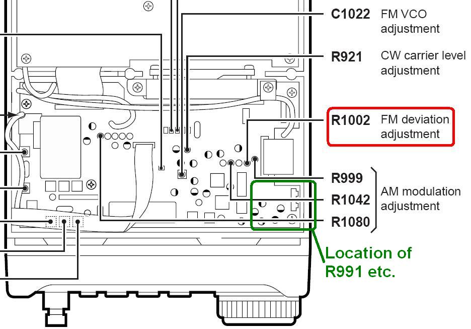
My IC-706MKIIG (and maybe all versions of the 706 radio) had very low CTCSS (Encode tone). I was dropping out of my 440 MHz repeater all the time. When I checked my 706 it only had 3 kHz maximum deviation, and only 300 Hz of CTCSS TX tone! I researched the web but could not find anything about raising the CTCSS, except that it could not be done! Being a Commercial Icom Dealer (Action Communications in Tucson, AZ) and radio systems engineer, I knew it could be done... somehow! I put my 706 on the bench and set the maximum deviation to 4.9 kHz, but still only had 400 Hz of CTCSS deviation (at 100.0 Hz tone frequency). Here's where the FM Deviation adjustment can be found:

There is no separate CTCSS adjustment; it is proportional to the main audio deviation level. But you can fix it.
On the right side of the radio there are two holes to access the Compression and Beep adjustment pots. On the main board inside the top of the radio, behind these holes, are the two pots: R945 and R896. R896 (Beep/Sidetone) is closest to the notched out part of the PC board, closer to the center of the radio, and also it is closer to the 12 chip parts laid out, three in a row, in four rows. Looking from R896 to the closest row of three chip parts, the center chip is a 680k resistor, R991. This is what we are looking for. This is inside the area outlined in green above. See the board layout diagram below:

R991 feeds CTCSS (sub-audible tone) to be mixed with the TX audio. It feeds it from C986 (0.1 chip cap) to R989 and R990. See the schematic diagram below (click on it for a larger view):
To increase the CTCSS, all you need to do is add another resistor on top of R991 to increase the CTCSS. I used a 1.5 meg-ohm surface-mount component to raise mine from 400 Hz to 650 Hz (that's 0.650 kHz), the minimum acceptable level. Pick the value of resistance to set whatever level of CTCSS deviation you want. (The official CTCSS level is 650 Hz to 850 Hz.) You can add a regular old style resistor across the chip, but soldering it will be hard, and you will need a long, small soldering iron.
I could have added a small 5 meg-ohm pot across R991 so I could adjust it, but I didn't want the weight hanging in the air held by the small caps, and it was not needed.
If you needed to lower your CTCSS level you would need to remove R991 and replace it with a higher value resistor.
My radio now works on my repeater without dropping out every other word.
Acknowledgements and Credits:
Information on component location, alignment, and the schematic diagram came from a PDF copy of the Icom IC-706MKIIG Service Manual. Additional information came from the official User's Manual.
Contact Information:
The author can be contacted at: kcØll [ at ] hotmail [ dot ] com.
Back to the top of the page
Up one level (Icom index)
Back to Home
This page originally posted on 07-Jun-2007.
Artistic layout and hand-coded HTML © Copyright 2007 and date of last update by repeater-builder staff.
This web page, this web site, the information presented in and on its pages and in these modifications and conversions is © Copyrighted 1995 and (date of last update) by Kevin Custer W3KKC and multiple originating authors. All Rights Reserved, including that of paper and web publication elsewhere.