|
If your in need of a high impedance COR Buffer/Driver,
here is a simple circuit that should be helpful in most cases.
This circuit can be built on a perforated construction board obtain from your
local RadioShack store. It is highly recommended that you use a shielded cable
when connecting the COR signal from the repeater to this driver circuit. To
proceed , follow these simple six steps:
Step 1
List of parts you'll need for this circuit.
Item |
Part Schematic ID |
Part Identification |
RadioShack Part Number |
1 |
U1 |
Operational Amplifier, TL084 |
276-1715 |
2 |
R1 |
100K ohm 1/4 watt resistor |
271-1347 |
3 |
R2 |
100K ohm 1/4 watt resistor |
271-1347 |
4 |
R3 |
10K ohm variable resistor |
271-1715 |
5 |
C1 |
.1uf 50V Capacitor |
272-109 |
6 |
|
8 pin socket for U1 |
272-1995 |
7 |
|
Perf board to hold circuit components |
276-148 |
Step 2
If necessary, remove the DB25 male connector from your
CAT controller. Unscrew the two "hold-together" screws to open the
connector. See Figure 1.

Step 3
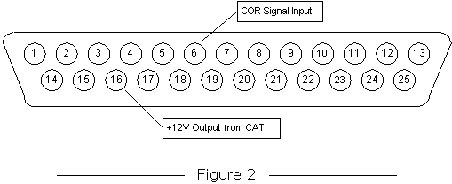
Carefully unsolder the wire connected to pin 6 of the
connector and bring that wire out the back of the connector. Solder additional
wires to pin 6 (CAT COR Input), pin 16 (+12VDC output), and pin 17 (Ground).
Refer to figure 2 for the correct pin location.

DB25 Male Connector
viewing from pin side.
Step 4
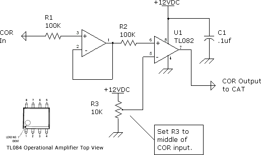
Build
the circuit on a perforated board following the schematic below. The DB25 wires
will connect as follows:
DB25 Pin Number |
Connect To Circuit |
6 |
Connect to U1 pin 7 |
16 |
+12VDC connect to U1 pin 8, C1 and one side of R3 |
17 |
Connect to U1 pin 4, C1 and other side of R3 |
COR signal from Repeater |
| Connect to 100K resistor R1 |

Step 5
Carefully re-assemble the DB25 connector and reconnect
to your CAT controller.
Step 6
Obtain a high-impedance voltmeter and make the following
measurements and calculations:
- Measure the voltage at pin 1 of amplifier U1.
- Key and Unkey a signal and record the two voltages (with/without COR).
- Calculate the center voltage between the two voltages in step 2.
- Measure the voltage of the wiper arm of R3.
- Adjust R3 until the voltage equals the calculated voltage from step 3.
Once adjusted and setup, the output of U1 pin 7 will provide a strong drive
voltage for your CAT controller.
|

