Back to Home
Motorola R2001-series
Communications System Analyzer
By Robert W. Meister WA1MIK

|
Back to Moto Test Equipment Back to Home |
Restoring the CRT on a Motorola R2001-series Communications System Analyzer By Robert W. Meister WA1MIK |
|
History:
I was given this unit for free on April 1st, 2016. Perhaps it WAS an April Fool's Joke. The unit was pretty much beat up. The rear feet were bent, loose, and extremely worn down. The covers were held on with one screw each. The carrying handle was bent at a strange angle. There was no front cover. The handles of some toggle switches were bent or broken. The center contact of the N-female connector was broken. The unit did power up, all the buttons and LEDs worked, and you could generate a 1 kHz tone and hear it on the loudspeaker, however the CRT was completely blank. As this unit relies on the CRT to display all of the various parameters, the unit is fairly useless without it. But I love a challenge.
Opening it up revealed why the CRT was dark: it had been completely unplugged. The tube socket was sitting behind the CRT, the high voltage lead was floating around, and the wires going to the trace rotation coil had been cut. The CRT itself looked brand new. There were no burn marks on the phosphor or any signs of dirt or dust. Someone had obviously swapped a bunch of boards, assemblies, and the CRT into this unit. I reconnected everything and turned it back on. After a few minutes I could barely see something on the CRT, but it was quite blurry and dim. At least it was working... sort of.
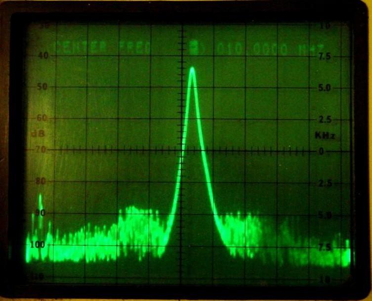
After adjusting some internal intensity pots, I determined that swept trace displays, like the oscilloscope, spectrum analyzer, and a few other modes, seemed to be nice and bright and clearly in focus. It was just the displays containing text that had a problem. This included the single line of text at the top of the spectrum analyzer, all of the memory lists, and the main monitor displays; all had problems. They just weren't bright or clear enough, and no adjustments would improve that. The brightness just reached a plateau and further increases would only make it blurrier but not brighter. Here's a photo of the CRT screen in spectrum analyzer mode, looking at the 10 MHz reference oscillator signal. Notice how the text at the top is almost unreadable.
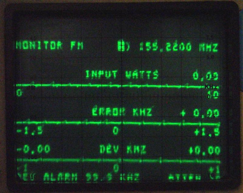
Here's a photo of one of the main analyzer display screens. The characters are fuzzy and dim. This is after my photo editing software "improved" the picture.
One of the first things I did was replace ALL the electrolytic capacitors in the Low-Voltage Power Supply and the High-Voltage Power Supply. This is covered in a separate article. I spent a lot of time over the next 15 months looking at scope signals and waveforms in an attempt to figure out why the text was dim while the swept traces seemed to be fine. I had Steve take photos of waveforms of the intensity signal that I compared to mine; they looked the same. I was somewhat tempted to send my CRT to him to swap into one of his working R2001 units, but I didn't want to risk loss or breakage of the CRT in transit. I could have easily swapped the A2 card (it contains the CRT sweep and intensity drivers) and the High-Voltage Power Supply but I was fairly sure the CRT was the problem. It acted as if there was a large capacitor between the grid and cathode, which allowed slow intensity changes, such as blanking/retrace of the sweep, to produce full brightness but inhibited rapid intensity changes required for text data. The beam intensity is switched on and off to "paint" the character dots on the screen as the horizontal sweep occurs.
Maybe The CRT Can Be Fixed:
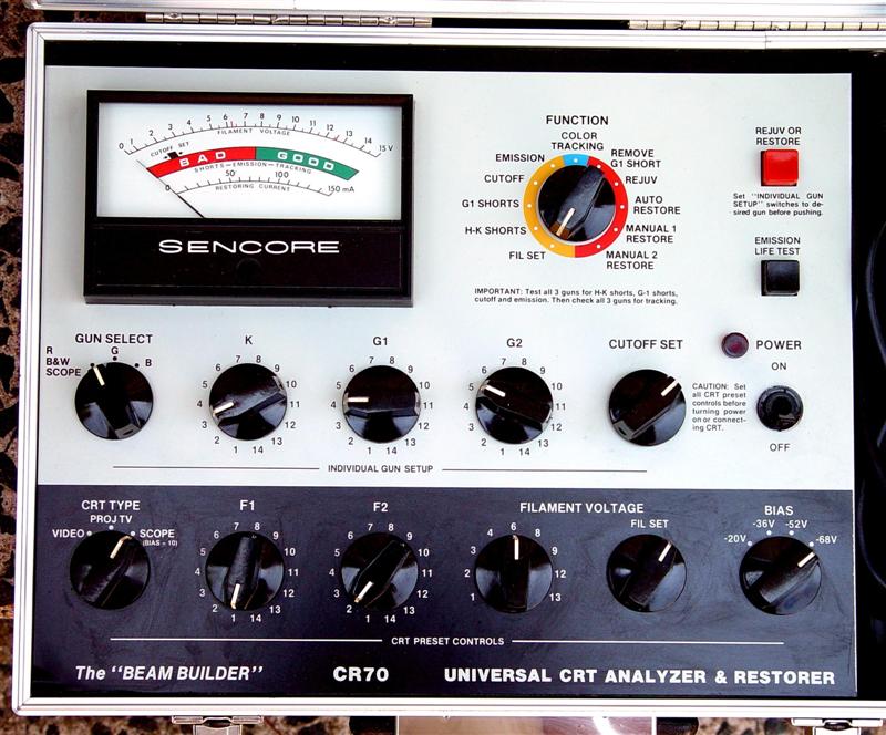
One day Steve reported he had purchased a CRT tester and rejuvenator because he had several R2001 units with bad CRTs and he wanted to try to get them going. We discussed the various pin numbers and their CRT element connections. Surprisingly, the tester had info for the CRT used in the R2001-series; not all versions of the setup book have that. He successfully restored several CRTs. We considered shipping the tester to me, but as it would have cost over $30 to ship each way, I decided to purchase the same unit he did for $50, which included shipping. It's hard to go wrong at that price. So in July 2017 I purchased a complete Sencore CR-70 and later bought a CD with manuals, which included a schematic diagram.
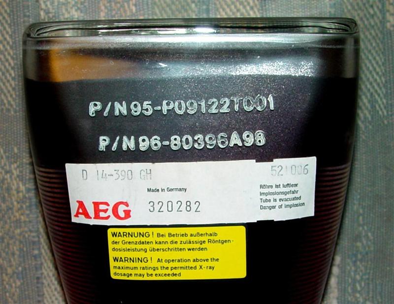
The CR-70 is a Universal CRT Analyzer and Restorer. It comes with six socket adapters, none of which can be used with the CRT in the R2001-series, but best of all it comes with a Universal Adapter, which has five clip-leads, allowing you to connect the tester to ANY CRT regardless of the base pin configuration. The seven adapters are all stored in foam compartments inside the top cover. There's also a thick book that has connection and switch settings for thousands of CRTs; this book is glued to the inside of the compartment cover. My CRT was stamped "D 14-390 GH" and the Sencore setup book had an entry for "D14-390GH"; close enough. Here's a photo of the labels on my AEG-brand CRT:
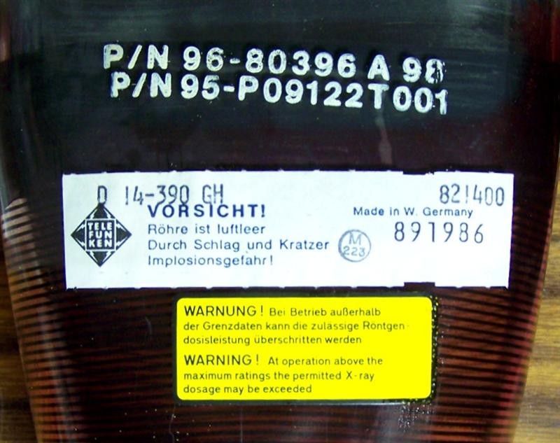
And here's a photo of the labels on Steve's Telefunken-brand CRT:
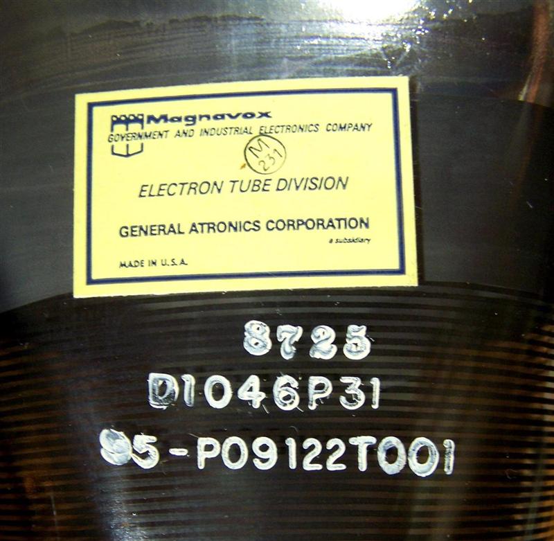
Motorola had previously used Magnavox CRTs in their service monitors but apparently switched to Telefunken/AEG due to reliability issues. The tubes have the same Motorola part number but different model numbers. The Sencore setup book does not have the Magnavox tube model listed, but you would use the same data as for the D14-390GH since the base pinout and other characteristics are identical. Here's a photo of the labels on a Magnavox-brand CRT, courtesy of Steve K7LJZ:
I performed all the self-check tests on the CR-70 and it passed them all. I did my homework and figured out which five CRT pins I needed to connect to. According to the book that came with the CR-70, I needed two pins for the filament, one for the cathode, one for the control grid, and one for the second grid. The schematic diagram of the R2001B clearly shows the filaments on pins 14 and 1, the cathode on pin 2, the control grid on pin 3, and several other elements, but nothing labeled second grid. The CR-70 book said to use pins 14, 1, 2, 3, and 4 for the various connections, so that's what I did. Pin 4 however is the FOCUS grid on the R2001B diagram so I was a bit suspicious, but I figured "they must know what they're doing" and I plodded ahead anyway. Here's a photo of the front of the unit showing the various switch positions and settings.
There are LOTS of CRT testers, analyzers, and rejuvenators out there. Your unit's settings will probably be different. If you do buy one, make sure it's complete and has something like the Universal Adapter, or clip leads you can attach to the CRT as needed.
Testing, Testing, 1, 2, 3:
I ran through all the tests the CR-70 has. Heater-to-Cathode Shorts: none (good). Grid 1 Shorts: none (good). Cutoff: it was always below the minimum value and it barely changed (bad). Emission: it barely moved the meter (bad). Steve and I had discussed the second grid pin and came to the conclusion that pin 7 (labeled ACCELERATOR in the manuals) was actually the second grid, so I tried connecting to pin 7 instead of pin 4. Nothing changed. I even tried raising the filament voltage to 9V but that didn't give me any more emission than at 6.3V.
I reconnected the second grid lead back to pin 4, and figuring I had nothing to lose, I ran through all of the rejuvenation, automatic restore, and manual restore procedures, with no apparent success.
I then put the second grid lead back on pin 7 and repeated the Cutoff test. This time the meter responded and moved to the correct spot on the scale (good). I repeated the Emission test: I now had over 90% on the scale out of 100% (good). So apparently one or more of the rejuvenation or restoration procedures DID have some effect and it may have fixed the CRT.
So, the correct connections are: filaments: pins 14 and 1, cathode: pin 2, control grid: pin 3, second grid: pin 7. The other switch and control settings on the CR-70 are correct in the listing for this tube: CRT Type: Scope, Neg Bias: 68V, Gun: B/W, Filament: 6.3V.
Success:
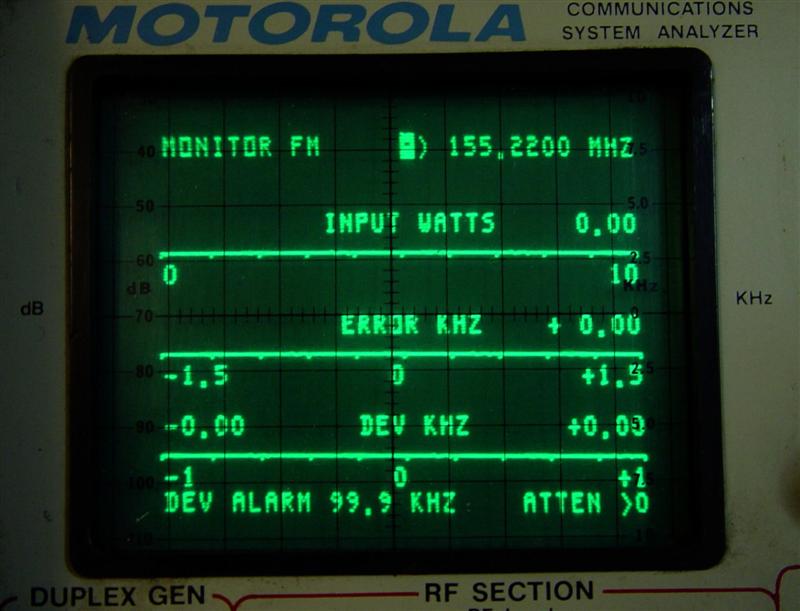
I reinstalled the CRT into my R2001B and turned it on. I was quite dismayed to see absolutely nothing on the CRT. Then I noticed that the front panel INTENSITY control was fully counter-clockwise (from some measuring I had done previously). I rotated it to about the ten o'clock position and saw a very nice, bright, focused, main display screen. I scrolled through all the other displays and found them all to be very readable and clear. I touched up the two intensity-related pots on the A2 card per the R2001B manual and was pleasantly surprised at the marked improvement in the display quality. The display got brighter and stayed in focus as I increased the Intensity control. This was a complete and total success. Here's a photo after rejuvenation. The camera apparently focused on the graticule in front of the CRT, so the CRT trace appears to be a bit fat and smoother than it really is. It is completely clear, crisp, and bright.
Contact Information:
The author can be contacted at: his-callsign [ at ] comcast [ dot ] net.
Back to the top of the page
Back to Moto Test Equipment
Back to Home
This article created 26-Mar-2018
This web site, the information presented in and on its pages and in these modifications and conversions is © Copyrighted 1995 and (date of last update) by Kevin Custer W3KKC and multiple originating authors. All Rights Reserved, including that of paper and web publication elsewhere.