Crystal
Heater Construction Article
By Bob
Dengler NO6B
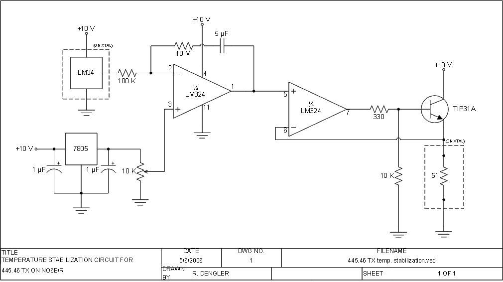
OK, here is the circuit I used - See image below. The original National Semiconductor circuit had a 30 K resistor in series with a 400 µF cap., both in parallel with the 100 K resistor on the input of the 1st LM324 section. I found that combo to actually destabilize the operation of the controller for this particular application, so I removed them & changed the 2 µF cap in series with the 10 megohm resistor to 5 µF. That capacitor is a non-polarized paper type; I believe a 4.7 µF non-polarized ceramic should work as well. The 1/4 watt heater resistor & LM34 temperature sensor are mounted on the same side of the crystal but separated as far apart as possible. Thermally conductive epoxy is used to mount the LM34 & 51 ohm 1/4 watt heater resistor onto the crystal.
For those who would like a complete kit with printed circuit board, or an assembled
and tested option please check this out:
Masters Communications CH-25
Measuring the LM34's output, it was very good: less than 0.2 °F
change. Keep in mind that other applications will probably require
a different feedback loop. The 400 µF cap & 30 K resistor
I removed across the 100 K resistor were probably for controlling much
larger systems with longer time lags between the heater & sensor.
HTML © Copyright January 11, 2007, Kevin K Custer W3KKC
Text, concept, images, etc., Copyright Bob Dengler NO6B
no6b at no6b dot com
All Rights Reserved