Back to Home
By Kevin K. Custer W3KKC

|
Up one level Back to Home |
Building 75 to 50 Ohm Matching Stubs for using CATV
jacketed hardline on 50 Ohm systems By Kevin K. Custer W3KKC |
|
Concept: To build a cheap interface between 75 Ohm CATV hardline and 50 Ohm radio systems. A Matching Stub will provide this interface within a reasonable bandwidth from the design length. The concept presented here eliminates all of the weak spots in the construction from several other companies.
Description: After meeting Paul Darwactor W8ZD at the Dayton Hamvention many years ago, I've been using 75 Ohm CATV cable as my transmission line for most of my several repeaters. Some of my machines have Paul's stubs on them and most have stubs on them that I have built. Paul stopped producing his matching stubs in 2001, so an alternative needed to be produced.
As my antenna engineering handbook suggests, impedance transformation will happen when a cable that is the length of an odd multiple of a quarter wavelength and posing impedance determined by the square root of the product of the two values to be matched, is positioned at the end of the line. This figures out to be 61.2 Ohms to match 75 to 50 Ohms.
Since I grew up around the CATV industry, I'm able to get many sizes of jacketed CATV hardline for little or nothing. Some of the sizes are too large for Paul's construction as the center conductor is too big for his concept. Long ago, CATV hardline was made of an aluminum sheath and a solid copper center conductor and was referred to as P1 or Parameter 1 cable. This construction created a situation called suck-out. Back then, the center conductor could recede back into the body of the cable, even on short runs of a few hundred feet, in extreme cold weather. This situation has been eliminated by using near like metals for the center conductor and sheath. This style cable, called P3, has a copper over aluminum center conductor (copper clad) and has been manufactured for the past 30 years. Paul's method of installing the copper stub on the aluminum cable creates a problem... dissimilar metal. The dissimilar metal problem along with not having a secure way of seizing the center conductor and the inability to interface with very large cable led me to improve on Paul's original concept. This article is not meant to demean Mr. Darwactor's construction, it's here as an alternative to those who want to build a better interface, or have the opportunity to obtain very large cable like CommScope's 1125 or "Inch and an eighth". It is important to use only jacketed hardline for duplex systems or systems that are on a commercial tower with shared services.
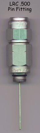
My concept uses the proper CATV "Pin connector" to mate with the cable. The matching stub is produced exactly the same for a given band / frequency. Since the correct connector is used, the problem with interfacing to a particular cable, the dissimilar metal on the coax sheath and the center conductor seizure problem is eliminated, however another problem is created. This problem is with the junction between the aluminum connector and the copper pipe which the stub outside is made of. This problem is eliminated by the use of a Stainless Steel insert. Stainless steel inserts with the correct thread interface can be procured from old CATV amplifier housings. Many manufacturers of CATV mainline amps use a Stainless insert bushing that is threaded to be a bit tougher than the plain aluminum housing. These inserts are factory threaded to accept the CATV connector, and are removed and modified for use in this matching stub.
Here is a picture of the stainless steel insert robbed from a C-COR
300 MHz. trunk station.
This image is magnified about 3.5 X for clarity.
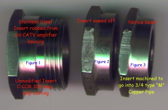
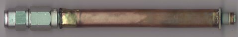
The insert is machined to be hammered into a length of ¾" type
"M" copper pipe. The method of machining can be anything from
using a real lathe to a grinder. Refer to figures A and B.
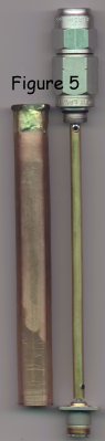
The length of the copper pipe, which makes the outside conductor, is
determined by the frequency of interest. This formula is used to
calculate the length in inches... 2880 divided by the operating
frequency in MHz, plus ½".
Example: Say we wanted to build a stub to cover the 2 meter ham
band. The stub should be figured for the lowest expected operating
frequency, in this case 144 MHz. The stub would then be figured like
this. 2880 / 144 = 20" plus ½" equals a grand total of 20
½"
 :
: 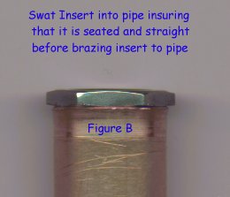
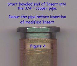
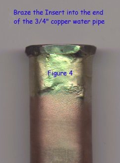
Clean up the ends of the pipe removing the sharp inside edge produced
by the pipe cutter. Install the modified SS insert by pressing or hammering
it into one end of the copper pipe. Using an acetylene torch and a thin
brazing rod, braze the insert (yes you can easily braze stainless steel) to
the end of the copper pipe to to make a quality interface receptacle for
the aluminum connector. Refer to figure 4.
Now that you have the outer conductor prepared, set it aside and start to build the inner conductor assembly.
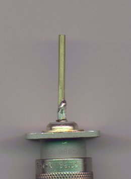
Start the inner conductor assembly by soldering a length of 3/32 solid
brass rod into the chassis connector of choice. Something around
an inch is fine as the length is not critical. A type N connector
is preferred for anything over 200 MHz.
 :
: 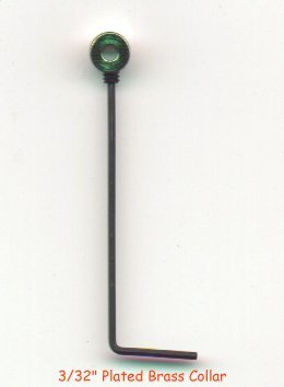
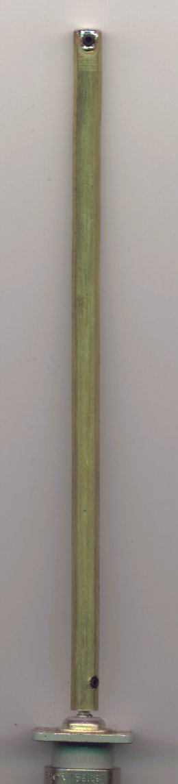
Cut a length of 9/32 hobby brass tube slightly longer than the overall length of the outer copper pipe. The overall length will be trimmed to exact size in a later step, so just be sure it's as long as the copper pipe and maybe a little more. A 3/32 plated brass collar is installed in the end of the brass tube by drilling a hole to allow the set screw to be passed through the side of the tube and into the collar. The place where you drill the hole will be determined by allowing an 1/8" gap between the end of the tube and the end of the connector. The hole size should present a tight fit to the set screw. Install the collar and seize the set screw. This distance allows enough spacing for good power handling capability while preserving the 61.2 Ohm impedance to the far end of the assembly. This collar is used to create a good connection between the 50 Ohm coaxial connector center pin and the hobby tube center conductor. After the assembly is tightened mechanically with the set screw, carefully solder the insert to the brass tube by using a small butane torch and common soft solder. A lot of solder is unnecessary because of the good mechanical connection. Be careful not to undo the solder connection at the pin that is inserted in the end of the 50 Ohm connector. Jigging the assembly in a vice to hold it all in place while soldering is a good idea. Insure the tube is exactly straight with the connector after soldering. This will ensure that the center conductor will be positioned in the center of the outer conductor throughout the length of the assembly.
 :
: 
Once the assembly cools the overall length of the center conductor tube can be determined and trimmed to size. Place the center conductor assembly inside the outer conductor by installing the brass tube in the end of the pipe without the SS insert. Be certain the connector is positioned such so the body of the connector is seated against the end of the pipe. By looking into the end of the pipe with the stainless insert, determine the length of the center conductor by subtracting 1/8" from the inside edge of the insert. The exact edge of the insert can also be determined by wobbling the center conductor inside the insert to mark the exact location of the inserts inside edge, then subtracting 1/8" from this mark. Cut the brass tube with a cutter designed for doing this. Prepare the cutoff end of the brass tube for insertion of another plated brass collar. This time the collar will be positioned at the very edge of the brass tube.
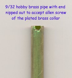
The end of the tube needs to be nipped to allow the actuation of the
set screw.
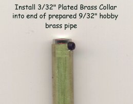
Install the plated brass insert and solder in place.
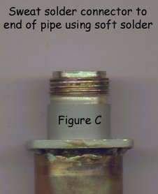
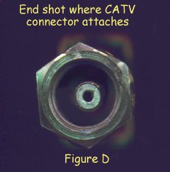
Now install the completed center conductor assembly back into the copper pipe as before and verify the clearance of the end of the brass tube and the SS insert. They should be close but not touch. If the fit seems ok, soft solder the 50 Ohm connector to the end of the copper pipe insuring the connector is centered. The 4 mounting holes make a good guide to tell when the connector is centered with the pipe. Refer to figure C.
After the assembly cools, drill a 1/8" hole in the side of the copper pipe to allow an Allen wrench to be inserted into the set screw on the Stainless insert end of the pipe.
Any size CATV connector can be inserted into the center conductor assembly and screwed tightly into the Stainless insert. Finish the assembly by seizing the center conductor collar to the pin of the CATV connector by tightening the set screw through the access hole in the side of the copper pipe.
If heat shrink tubing is going to be placed over the assembly, wrap some electrical tape over the access hole to prevent the inert goo from protruding inside the stub when shrinking.
Material Suppliers:
Local Hardware:
Length of ¾" type "M" copper pipe.
Hobby Store:
K&S Engineering, Round brass
tubing; Stock No. 1150 (3') or 132 (1')
K&S Engineering, Solid brass
rod; Stock No. 163 (1')
Du-Bro 3/32" Plated Brass, "Dura-Collars"; Cat No. 596 (Pkg. of 12)
Additional Information:
Quantum Reach Jacketed CATV Hardline losses
Back to the top of the page
Up one level
Back to Home
Article text © Copyright March 29 2000 Kevin Custer W3KKC
Artistic layout and hand-coded HTML © Copyright 2006 and date of
last update by repeater-builder.com.
This web page, this web site, the information presented in and on its pages and in these modifications and conversions is © Copyrighted 1995 and (date of last update) by Kevin Custer W3KKC and multiple originating authors. All Rights Reserved, including that of paper and web publication elsewhere.