Build a 2-Meter Duplexer
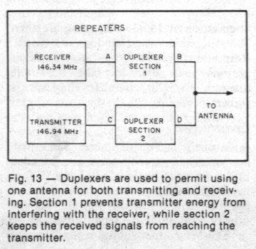
Walk up to any ham who has already put a repeater on the air and ask him, "What's the toughest technical problem you had with it?" He will probably say that obtaining sufficient signal isolation between the transmitter and receiver was the toughest. Satisfactory isolation can be gotten, but always for a price. Many of the solutions to this problem compromise receiver sensitivity or transmitter power output. Other solutions throw off the balance between receiver and transmitter coverage areas. When a duplexer is used, insertion loss is the compromise. But any insertion loss is more than offset by the use of one antenna for both the transmitter and receiver. Using one antenna assures equal antenna patterns for both transmitting and receiving. Duplexers have been in use by many commercially operated repeaters for many years. A large number of these systems use frequency separation of two percent or more between input and output channels. Amateur 2-meter repeaters have a separation of only 0.4 percent, or 600 kHz. A decrease in frequency separation makes the job of providing good isolation even more difficult. A duplexer must meet some basic requirements. It must attenuate the transmitter carrier, this prevents receiver overloading, which in turn would reduce receiver sensitivity. A duplexer must also attenuate any noise or spurious energy from the transmitter on or near the receive frequency. In addition, a duplexer must provide a proper match between transmitter, antenna and receiver. If you are having trouble visualizing these functions, Fig. 13 will help. Transmitter output on 146.94 MHz going from point C to D should not be attenuated. However, the transmitter energy should be greatly attenuated between points B and A. Duplexer section 2 should attenuate any noise or signals that are on or near the receiver input frequency of 146.34 MHz. For good reception, the noise and spurious signal level must be less than -130 dB (0 dBm = 1 milliwatt into 50 ohms). Typical transmitter noise 600 kHz from the carrier frequency is 80 dB below the transmitter power output. For 60 watts of output (+48 dBm), the noise is -32 dBm. The duplexer must make up the difference between - 32 and -130 dBm, or -98 dBm. Now, let's talk about the received signal. First of all, the received signal must go from point B to A with a minimum of attenuation. Section 1 of the duplexer needs to provide enough attenuation of transmitted energy to prevent receiver overload. For an average receiver, the transmitter signal must be less than -30 dBm to meet this requirement. It is the job of duplexer section 1 to make up the difference between the transmitter output of + 48 dBm and the receiver overload point of -30 dBm. One thing that many duplexers have in common is the use of high-Q coaxial cavities. The loaded Q of a cavity is affected by electrical conductivity and dielectric losses. Surface loss can be reduced by silver plating, although clean copper is adequate. Air dielectric duplexers cavities are the most practical for amateur duplexers.
The Circuit:
A quarter wavelength resonator was selected for this duplexer design.
The length of the center conductor is adjusted by turning a threaded rod,
which tunes the cavity to frequency. Energy is coupled into and out of
the tuned circuit by the coupling loops extending through the top plate.
The cavity functions as a series resonant circuit. When a capacitor or
inductor is connected across a series resonant circuit, an anti resonant
notch is produced, and the resonant frequency is shifted. If a capacitor
is added, the notch appears below the resonant frequency. Adding
an inductance will make the notch appear above the resonant frequency,
and the value of either component will determine the spacing between the
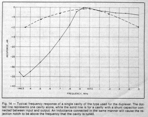
notch and the resonant frequency. Fig.
14 shows the band-pass characteristics of the cavity with shunt elements.
With the cavity tuned to 146.94 MHz, and a shunt capacitor connected from
input to output, a 146.34 MHz signal is attenuated 35 dB. With a cavity
having an inductance across it, and tuned to 146.34 MHz, the attenuation
at 146.94 MHz is 35 dB. Insertion loss in both cases is 0.4 dB. Three cavities
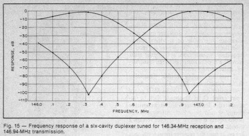
with a shunt capacitor are tuned to 146.94 MHz and connected together with
short lengths of coaxial cable. The attenuation at 146.34 MHz is more than
100 dB, while insertion loss is 1.5 dB. Response curves for a six
cavity duplexer are given in Fig. 15.
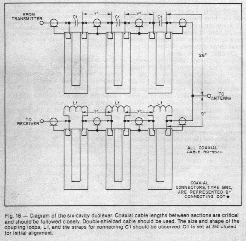
The schematic diagram for the complete duplexer is shown in Fig. 16.
Construction:
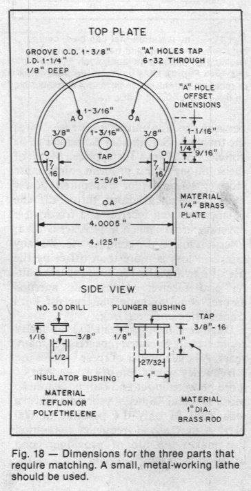
A small lathe for metal work will machine the brass top plate, the
threaded tuning plunger bushing and the Teflon insulator bushing.
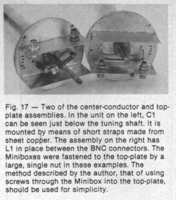
Fig. 17 shows the completed top
plate assemblies, one with a capacitor, one with inductor. The
dimensions of these parts are given in Fig.
18. All the other parts can be made with hand tools. "DWV" copper pipe
is used for the outer conductor of the cavities.
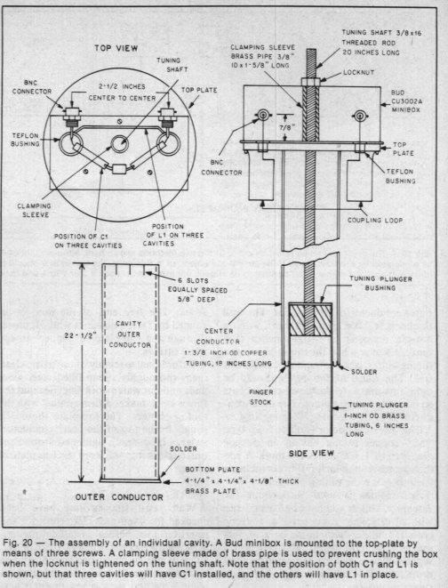
See Fig. 20 for a complete overview
of an individual cavity. The wall thickness is 0.058 inch (1.5 mm),
with an outside diameter of 4-1/8 inches (105 mm). When you buy the pipe,
borrow a tubing cutter large enough to handle this size. The wheel of the
cutter should be tight and sharp. Make slow, careful cuts so the ends will
be square. The outer conductor is 22-1/2 inches (571 mm) long. The inner
conductor is made from type "M" copper tubing having an outside diameter
of 1-3/8 inches (35 mm). A six inch length of one inch OD brass tubing is
used to make the tuning plunger. Soft solder is used throughout the
assembly. Unless you have had experience with silver solder, do not use it.
Eutectic type 157 solder with paste or acid flux makes very good joints.
This type has a slightly higher melting temperature than ordinary Tin-Lead
alloy and has considerably greater strength. First solder the inner
conductor to the top plate. Then finger stock can be soldered inside the
lower end of the inner conductor, temporarily held in place with a plug
made of aluminum or stainless steel. While soldering, do not allow the
flame from the torch to overheat the finger stock. The plunger bushing is
soldered into the tuning plunger and a 20 inch length of threaded rod is
soldered into the bushing. Cut six slots in the top of the outer
conductor. They should be 5/8 inch (16 mm) deep and equally spaced around
the tubing. The bottom end of the 4 inch tubing is soldered to the square
bottom plate. Because the center conductor has no support at one end,
the cavities must be mounted vertically. The size and position of
the tuning loops are critical. Follow the
given dimensions
closely. Both loops should be 1/8 inch (3.2 mm) away from the center conductor
on opposite sides. Connect a solder lug to the ground end of the loop.
Then fasten the lug to the top plate with a screw. The free end of the
loop is insulated by Teflon bushings where it passes through the top plate
to connect to the BNC fittings. Before final assembly of the parts,
clean them thoroughly. Soap filled steel wool pads and hot water work fine.
See that the finger stock makes a firm contact with the tuning plunger.
The top plate should fit snugly in the top of the outer conductor.
A large hose clamp tightened around the outer conductor will keep the top
plate in place.
Tuning:
Wait until the cavities have been checked for band-pass characteristics
and insertion loss before installing the anti-resonant elements, C1 and
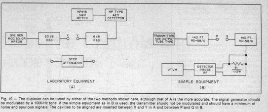
L1. See Fig. 14. It is preferable to use
laboratory test equipment when tuning the duplexer. A second method uses
a low power transmitter with an rf detector and a VTVM. Both methods
are shown in Fig. 19. With the test
equipment connected as shown in Fig. 19A,
adjust the signal generator frequency to the desired repeater input frequency.
Connect a calibrated step attenuator between points X and Y. With no attenuation,
adjust the HP-415 for 0 on the 20 dB scale. You can check the calibration
of the 415 by switching in different amounts of attenuation and noting
the meter reading. You might note a small error at either high or very
low signal levels. Next, remove the step attenuator and replace it with
a cavity that has the shunt inductor, L1, in place. Adjust the tuning
screw for maximum reading on the 415 meter. Remove the cavity and connect
point X to Y. Set the signal generator to the repeater output frequency
and adjust the 415 for a 0 reading on the 20 dB scale. Reinsert the cavity
between X and Y and adjust the cavity tuning for minimum reading on the
415. The notch should be sharp and have a minimum depth of -35 dB. It is
important to maintain this minimum reading on the meter while tightening
the lock nut on the tuning shaft. To check the insertion loss of
the cavity, the output from the signal generator should be reduced, and
the calibration of the 415 meter checked on the 50 dB expanded scale. Use
a fixed 1 dB attenuator to make certain the error is less than 0.1 dB.
Replace the attenuator with the cavity and read the loss. The insertion
loss should be 0.5 dB or less. The procedure is the same for tuning all
six cavities, except that the frequencies are reversed for those that have
the shunt capacitor installed.
Adjustment with Minimum Equipment:
Try getting a tube transmitter when using this method of adjustment.
You will want a minimum of spurious signals, otherwise, there will be a
lot of false indications. The VTVM should be capable of reading 0.5 volt
or less, full scale. The rf probe should be good to 100 MHz or higher.
Sections of RG-58/U coaxial cable are used as attenuators. See Fig. 19B. The loss in these 140 foot
sections is nearly 10 dB and will help isolate the transmitter in case
of mismatch during tuning. Set the transmitter on the repeater input
frequency and connect P and Q. Obtain a reading between 1 and 3 volts
on the VTVM. Insert a cavity with shunt capacitors in place between
P and Q and adjust the cavity tuning for minimum reading on the
VTVM. It should read between 0.01 and 0.05 volt. You can calculate the
rejection in dB by the formula 20 log V1/V2. It should be -35 dB, minimum.
Check insertion loss by putting the transmitter on the repeater output
frequency and noting the VTVM reading with the cavity in and out of the
circuit. You can make a 0.5 dB attenuator from seven feet (2.13 m)
of RG-58/U. This seven foot section can be used to check the calibration
of the detector probe and the VTVM. Cavities using a shunt inductance can
be tuned the same way but with the frequencies reversed. If you try to
tune two or more cavities connected together, transmitter noise can cause
the rejection readings to be low. In other words, there will be less
attenuation.
Results:
This duplexer is conservatively rated at 150 watts input, but it should
withstand up to 300 watts. Silver plating the interior of the cavities
is a good idea if the input power will exceed 150 watts. A duplexer using
plated cavities has an insertion loss of under 1 dB, and a rejection of
more than - 100 dB. Unplated cavities should be taken apart every two years,
cleaned thoroughly, and retuned.
Miscellaneous Notes:
1) Double shielded cable is a must throughout the system.
2) The VSWR from the antenna should not exceed 1.2:1 for proper duplexer
performance.
3) Good shielding of the transmitter and receiver at the repeater is
essential.
4) The antenna should have four or more wavelengths of vertical separation
from the repeater.
5) Conductors in the near field of the antenna should be well bonded
and grounded to eliminate noise.
6) The feed line should be well bonded and secured to the tower or
mast.
7) Feed lines from other antenna in the near field of the repeater
antennas should be well bonded and as far from the repeater antenna as
possible.
8) Individual cavities or pairs can be used to improve the performance
of split antenna or split site repeaters.
9) Individual cavities can be used to help solve intermodulation problems.
This article is part of the "Repeater Builder's Technical Information Page."
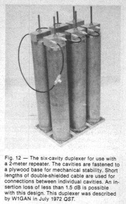
Original article appeared QST magazine as described by
W1GAN July 1972.
The article also appeared in the ARRL Antenna Book, and in the FM & Repeaters Manual.
Copyright ARRL, All Rights Reserved.
This web page created September 1999 and is © Copyright 1999 by Kevin Custer W3KKC,
All Rights Reserved.
This web page, this web site, the information presented in and on its pages and in these modifications and conversions is © Copyrighted 1995 and (date of last update) by Kevin Custer W3KKC and multiple originating authors. All Rights Reserved, including that of paper and web publication elsewhere.