PSE-508 MASTR II Repeater Setup
Setting Up Your MASTR-II Station Repeater
We've gotten a number of tech-support calls about intermittent problems that are caused
by MASTR-II station configurations that are not compatible with repeater usage. Not all
MASTR-II stations were originally sold as repeaters. To configure your station for repeater
use, some jumpers may need to be cut or added on the 10-volt regulator card. These mods are
described in the 10-volt regulator LBI, number 30704G, which can be downloaded from the
Repeater-Builder website here. (Also, if you
can afford it, give them a donation. They operate a super technical site that you can use
to solve a lot of problems and improve your repeater operation).
- First of all, remove all GE boards from the card rack. Examine the 10-volt regulator
card and refer to the picture below. The picture shows the component side of the board with
the heat sink removed. Note that it is not necessary to remove the heat sink to perform the
mod as there is plenty of room under it (or the jumpers may be installed on the solder side).
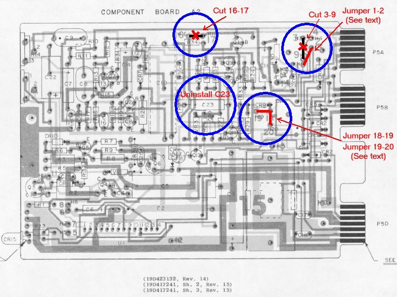
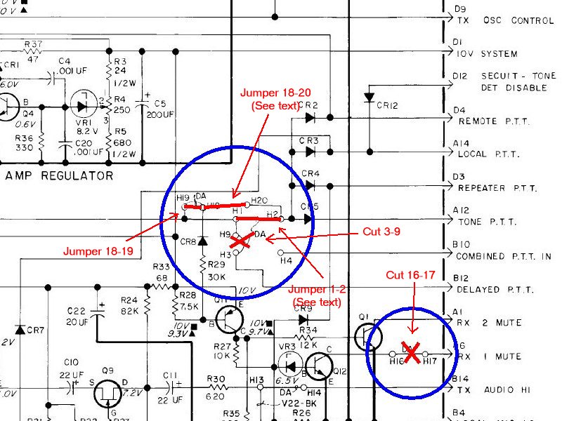
- Locate the jumpers on the 10-volt regulator card. Jumpers 16 and 17 are located under
the heat sink on the upper edge of the board. Jumpers 18, 19, and 20 are located under the
heat sink on the lower right. Jumpers 1, 2, 3, and 9 are located on the upper-right corner.
- Cut: 3-9, and 16-17.
- Some cards already have 18-20 jumpered. If this is the case, add a jumper from 18-19. If
18-20 is not jumpered already, you can either jumper 18-19-20, or 18-19 and 19-20.
- Check that C23 is either cut or uninstalled.
- Reinstall the 10-volt regulator and the PSE-508 controller. Do not install any other GE
cards. Below is a picture of the 10-volt regulator schematic, showing the modifications: