Back to Home
Index Page
Originally Compiled by Mike Morris WA6ILQ
Improved On and Maintained by Robert Meister WA1MIK (SK)
Currently Maintained by Mike Morris WA6ILQ.

|
Up one level (Moto Index) Back to Home |
The MSR2000 Station Index Page Originally Compiled by Mike Morris WA6ILQ Improved On and Maintained by Robert Meister WA1MIK (SK) Currently Maintained by Mike Morris WA6ILQ. |
|
While Motorola literature includes a space in the product name (MSR 2000),
we've removed the space on this web page and most of the accompanying articles.
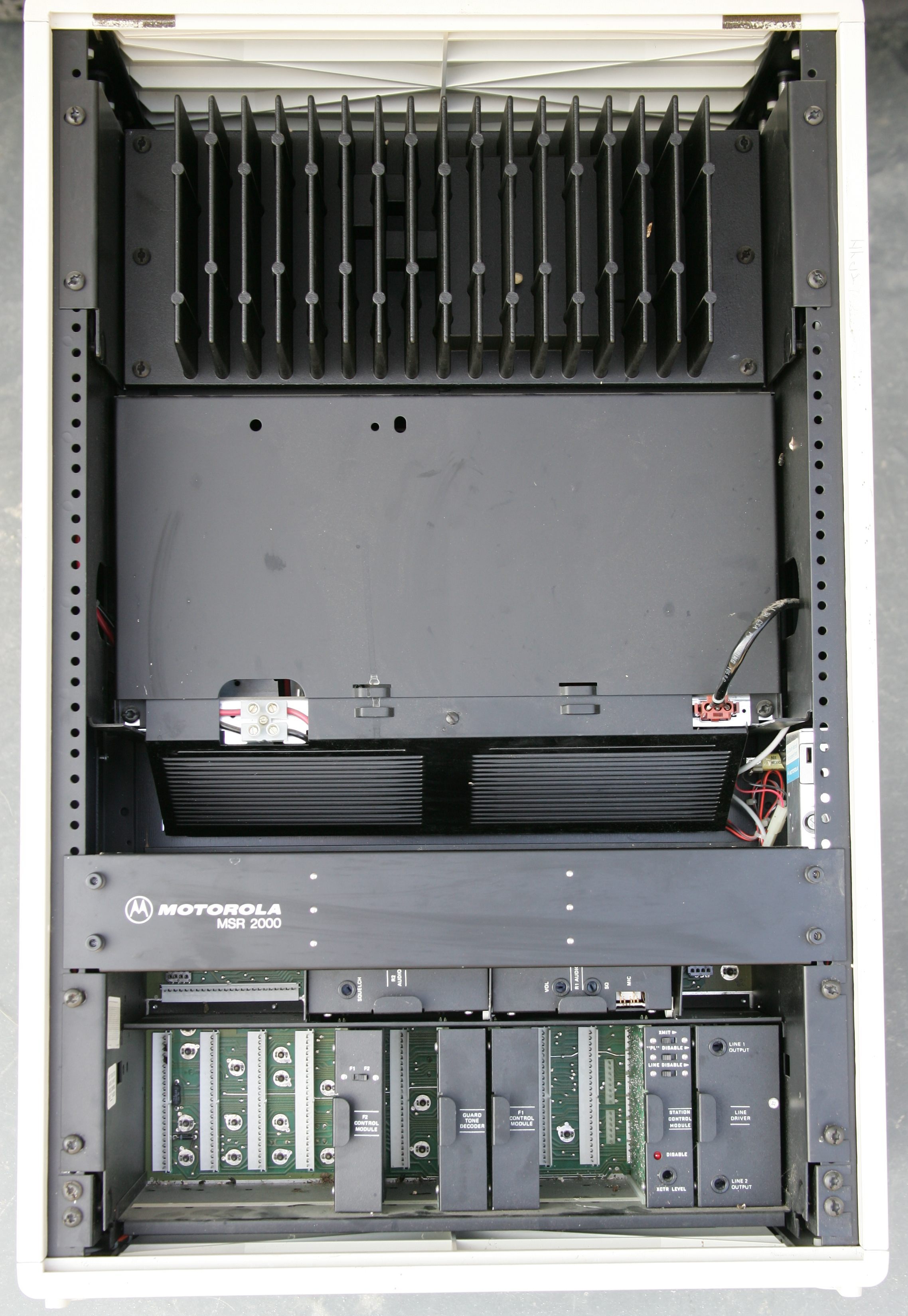
Click on the photo above for a larger image.
Information and Modification Articles:
|
|
MSR2000 Information, Modifications, Photos, Hints, Tips by Mike Morris WA6ILQ There is a lot more MSR2000 information here. |
|
|
Channel Elements for the Mitrek or MSR2000 by Mike Morris WA6ILQ |
|
|
Conversion and interfacing of an MSR2000 station to an external repeater
controller by Henry Wingate K4HAL While the author used a CAT200B controller, the information applies to most other units. |
|
|
A status display for the MSR2000 station by Henry Wingate K4HAL Put that empty slot to work. A few LEDs can go a long way towards diagnosing control problems. |
|
|
Connecting a CAT250 controller to an MSR2000 repeater by Nate Bargmann
NØNB The author describes the conversion and interfacing procedure for the WØDOD repeater. |
|
|
MSR2000 Conversion by David Stanford K7IOU (offsite link) Yet another group's conversion project using a CAT250 controller. |
|
|
Modifications to the MSR2000 cards for the VE6NHB repeater by VESBS
(offsite link) Again, a few LEDs and switches can make all the difference. Several cards were modified. Full documentation is provided. |
|
|
Documentation on the TLN6721CDX TX Alarm Card |
|
|
In-cabinet Repeater Controller for the MSR2000 Station by Eric
Grabowski KH6CQ. 260 kB PDF Eric mounted an NHRC-4 controller onto a spare card that plugs right into the MSR2000. Very clean; very neat. Well-done article. |
|
|
Adding an ID-8 to a MICOR or MSR2000 Shelf by Jerry Matthews WAØUZI This article also applies to the MICOR and Motrac/Motran series of stations with plug-in card shelves. |
|
|
Adding an ID-O-Matic to an MSR2000 Station by Eric Grabowski KH6CQ.
278 kB PDF Eric added an ID-O-Matic II Morse identifier board to an MSR2000 squelch gate module and mounted both boards behind a double-wide front panel fashioned from an MSR2000 Line Driver module. Another well-done article. More info is available at the link below. |
|
|
The ID-O-Matic kit by NØXAS (offsite link) Another low-cost CW ID solution that can be added to an MSR2000 repeater. |
|
|
Detailed audio path diagram for the MSR2000 Station by Eric Grabowski KH6CQ. 35 kB PDF |
|
|
Running D-STAR on a Motorola MSR2000 VHF Repeater by Ron Wright N9EE. A D-STAR repeater controller can be easily added to an MSR2000. |
Manuals and PDF Files:
|
|
VHF MSR2000 Station Instruction Manual 6881061E50-B 15 MB PDF A previous revision of the VHF Station Instruction Manual below. |
||||||||||||||
|
|
The entire VHF Station Instruction Manual 6881061E50-C 13 MB PDF The Control and Audio manual (6881061E40C) below covers the control shelf. |
||||||||||||||
|
|||||||||||||||
|
|
The entire MSR2000 Control and Audio manual 6881061E40-C 18 MB PDF This is the companion manual to the VHF and UHF station instruction manuals. |
||||||||||||||
|
|||||||||||||||
|
|
VHF MSR2000 Exciter 4.2 MB PDF TLD923xA, TLD924xA Series Exciters. |
||||||||||||||
|
|
VHF MSR2000 Continuous-duty Power Amplifier 2.8 MB PDF TLD260xA Series Continuous Duty Power Amplifiers. |
||||||||||||||
|
|
VHF MSR2000 Intermittent-duty Power Amplifier 2.9 MB PDF TLD2532A Intermittent Duty Power Amplifier. |
||||||||||||||
|
|
VHF MSR2000 Receiver 3.3 MB PDF TRD617xA, TRD618xA, TRD619xA Series Receivers. |
||||||||||||||
|
|
VHF MSR2000 TRD6182A Receiver Schematic 619 kB PDF | ||||||||||||||
|
|
VHF MSR2000 Receiver Alignment 180 kB PDF | ||||||||||||||
|
|
VHF MSR2000 Transmitter Alignment 4.0 MB PDF | ||||||||||||||
|
|
UHF MSR2000 Exciter 1.8 MB PDF TLE5502A Simplex Exciter; TLE5512A Duplex Exciter. |
||||||||||||||
|
|
UHF MSR2000 TLD9232B Exciter Schematic 555 kB PDF | ||||||||||||||
|
|
UHF MSR2000 Power Amplifier 2.1 MB PDF TLE228xA Series Power Amplifiers. |
||||||||||||||
|
|
UHF MSR2000 Receiver 1.8 MB PDF TRE616xA, TRE617xA Series Receivers. |
||||||||||||||
|
|
UHF MSR2000 Receiver Alignment 175 kB PDF | ||||||||||||||
|
|
UHF MSR2000 Transmitter Alignment 1.3 MB PDF | ||||||||||||||
|
|
UHF MSR2000 Accessories 2.3 MB PDF RF preamplifier, two-receiver coupler, duplexer, antenna switch. There is a better scan of the duplexer section here. |
||||||||||||||
|
|
MSR2000 Backplane Wiring 2.5 MB PDF Signal routing, wiring lists, and connector pinouts. |
||||||||||||||
|
|
MSR2000 TLN6721CDX Alarm Module 2.2 MB PDF See the separate TLN6721 Alarm Card article above. |
||||||||||||||
|
|
MSR2000 TPN1191A Standard Power Supply 3.5 MB PDF Includes 9.6V and 13.8V regulators (TRN5119A Auxiliary Regulator Circuit Board). |
||||||||||||||
|
|
MSR2000 TPN1192A Battery-reverting/charging Power Supply 5.5 MB PDF Includes 9.6V and 13.8V regulators (TRN5119A Auxiliary Regulator Circuit Board). |
||||||||||||||
|
|
MSR2000 TRN5069A Audio/Squelch Card Schematic 442 kB PDF | ||||||||||||||
|
|
MSR2000 TRN5075A PL Encoder/Decoder Card Schematic 423 kB PDF | ||||||||||||||
|
|
MSR2000 TRN5079A DC Metering and TRN5080A Service Intercom with Speaker 527 kB PDF | ||||||||||||||
|
|
MSR2000 TRN5119B Auxiliary Regulator for TPN1191A power supply 305 kB PDF | ||||||||||||||
|
|
MSR2000 TRN5321A Station Control Card Schematic 343 kB PDF | ||||||||||||||
|
|
MSR2000 TRN5329A Multiple PL Decoder Module 2 MB PDF | ||||||||||||||
|
|
MSR2000 TRN5331B Squelch Gate Card Schematic 509 kB PDF | ||||||||||||||
|
|
MSR2000 Jumper Tables Courtesy of George Henry KA3HSW. 160 kB PDF | ||||||||||||||
|
|
QLN2812A CW Identification Module Field Modification Kit 1 MB PDF QLN2812A is the kit number, the document covers two different circuit boards, the QRN8424B (for a Micor station) and QRN8425B (for the MSR2000 station). The cable is the QKN7547A. |
||||||||||||||
|
|
TLN640CDX Morse Identifier Module 5.9 MB PDF |
Back to the top of the page
Up one level
Back to Home
This page was created November 3, 2012 from the MSR2000 Information page.
Artistic layout and hand-coded HTML © Copyright 2012 by Robert Meister WA1MIK.
This web page, this web site, the information presented in and on its pages and in these modifications and conversions is © Copyrighted 1995 and (date of last update) by Kevin Custer W3KKC and multiple originating authors. All Rights Reserved, including that of paper and web publication elsewhere.