Back to Home
TRN6005 DPL code plugs
Information and photos by Jerry Matthews WAØUZI
HTML'd and Maintained by Mike Morris WA6ILQ
The first photo is by WA6ILQ, the rest are by Jerry Matthews WAØUZI.
|
Back to the Motorola Index Back to Home |
How to make your own TRN6005 DPL code plugs Information and photos by Jerry Matthews WAØUZI HTML'd and Maintained by Mike Morris WA6ILQ The first photo is by WA6ILQ, the rest are by Jerry Matthews WAØUZI. |
|
Digital PL is a 23-bit digital bit stream system that is totally incompatible with tone PL.
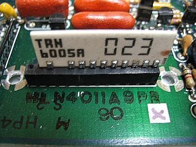
Above is shown a stock TRN6005 DPL code plug inserted into a Mitrek HLN4011 DPL
board. Note that the socket has two extra pins on the left - pins #11 and #12. They
are used by the mobile two-code adapter which provides different codes for transmit and receive
in a single mobile radio (sometimes called "split codes").
Note:
1) the socket and module pins are numbered from RIGHT to LEFT,
2) the gap between pins 9 and 10 does not count as a pin position.
This right-to-left pin numbering and pin skipping is the total opposite of several other
Motorola products that use this same socket!
You can click on any photo below for a larger image.
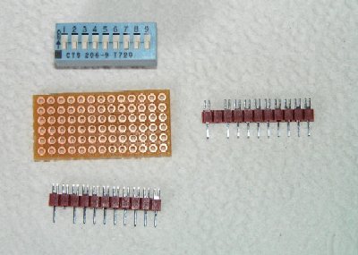 Photo 1 - the parts |
|
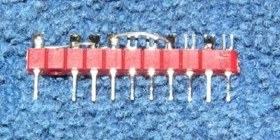 Photo 2 - side view |
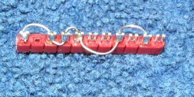 Photo 3 - top view |
Two photos of a quickie homebrew element made from a length of DigiKey A115-ND contact header. This part comes as a single strip of 25 pins on 1/10 inch spacing, in the above picture it's broken at 11 pins. The second pin from the left can be cut off (as shown in photos 5 and 6 below) or removed by heating the pin with a soldering iron and lifting it out just as the plastic softens (as shown above). A wire is then soldered from the leftmost pin (#10, the common pin) to the pins that are needed to produce the code needed, in this case 712).
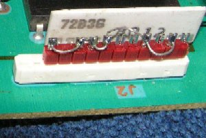
Photo 4
This photo shows it installed in a MICOR base station / repeater control card. Yes, there are two open pin holes on the left side of the socket, they are just washed out in the photo. The white component labeled "72B36" is actually behind the code plug socket (look at the left side of photo 8 and the top of photo 9 below).
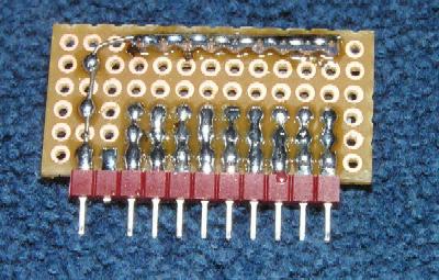 Photo 5 |
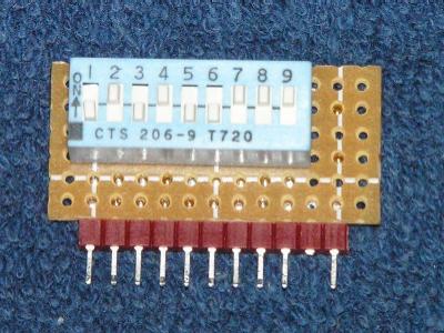 Photo 6 |
Two photos of a programmable homebrew element made by taking the same modified component header and adding a piece of perfboard and a 9 position DigiKey CT2069-ND DIP switch. The extra pin was not removed from the plastic strip to provide that much extra stiffening for mounting the perf-board. Make sure you mount the switch exactly as shown so the switch numbers match the bit numbers on the DPL code plug programming chart. Switch number 9 needs to be connected to the pin adjacent to the lonesome pin, and the DIP switch needs to be facing the inside of the unit shown - see the next group of photos (if you are building a switch-based code plug for a different type of equipment you may need to modify the construction technique shown to match the available space in that unit). Radio Shack sells a pad-per-hole perf board that works fine for this project, just cut it so you have exactly 6 by 13 VISIBLE holes. The two extra holes at the bottom are necessary to produce enough clearance for the module to fit into many Motorola products such as the TRN6166A card shown. First solder the 11 pins of the component header to the pads along one of the long edges of the board. Do not use excessive heat when soldering the pins! Bend the row of switch pins nearest the header down and just solder bridge the pads to make contact between the DIP switch and the header. Use a a bare #22, #24, #26 or #28 wire along the upper row of pins and solder them together and route the wire to the common pin #10. In the photo the switch is set to code 247.
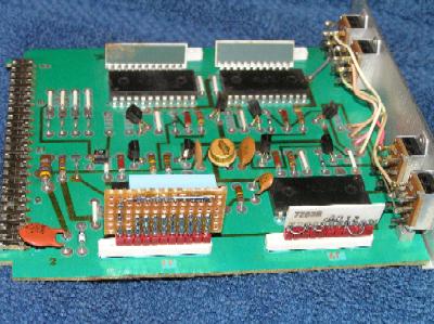 Photo 7 |
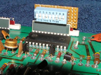 Photo 8 |
|
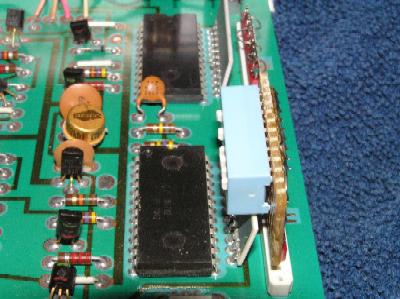 Photo 9 |
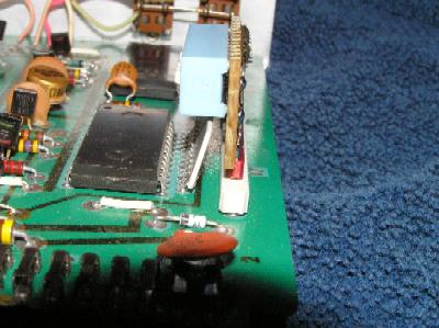 Photo 10 |
|
Four photos of both homebrew elements installed into a MICOR repeater quad Digital Private Line (DPL) card - a TRN6166A or TRN6166B that goes in slot #11 of the standard (non-community and non-DVP) repeater. That slot is normally used for a Single Tone Decoder, a Quad PL tone decoder, or a Voting card). Photos 8, 9 and 10 show why the extra two holes worth of clearance under the DIP switch mentioned above is needed - a ceramic component network sits adjacent to the DPL code plug socket. Do not try and move the network out of the way by bending the leads... the network is somewhat fragile, the pins are very stiff, and the ceramic will fracture right above the pins long before the stiff leads bend (been there, done that, the card ended up in the "to be cannibalized" bin). Just leave the ceramic network alone and work around it.
|
| |||||||||||||||||||||||||||||||||||||||||||||||||||||||||||||||||||||||||||||||||||||||||||||||||||||||||||||||||||||||||||||||||||||||||||||||||||||||||||||||||||||||||||||||||||||||||||||||||||||||||||||||||||||||||||||||||||||||||||||||||||||||||||||||||||||||||||||||||||||||||||||||||||||||||||||||||||||||||||||||||||||||||||||||||||||||||||||||||||||||||||||||||||||||||||||||||||||||||||||||||||||||||||||||||||||||||||||||||||||||||||||||||||||||||||||||||||||||||||||||||||||||||||||||||||||||||||||||||||||||||||||||||||||||||||||||||||||||||||||||||||||||||||||||||||||||||||||||||||||||||||||||||||||||||||||||||||||||||||||||||||||||||||||||||||||||||||||||||||||||||||||||||||||||||||||||||||||||||||||||||||||||||||||||||||||||||||||||||||||||||||||||||||||||||||||||||||||||||||||||||||||||||||||||||||||||||||||||||||||||||||||||||||||||||||||||||||||||||||||||||||||||||||||||||||||||||||||||||||||||||||||||||||||||||||||||||||||
Note that if for some reason you need to "flip over" the RX local oscillator / multiplier (the injection chain) to the opposite side (i.e. go from low side injection to high side or vice versa) you will discover that any digital information (dpl or data) will be inverted at the discriminator output. This can cause problems if the decoder does not have an option for inverted DPL. The table below may help.
| Normal | Inverted | Normal | Inverted | Normal | Inverted | ||
| 023 | 047 | 223 | 134 | 445 | 043 | ||
| 025 | 244 | 225 | 122 | 446 | 255 | ||
| 026 | 464 | 226 | 411 | 452 | 053 | ||
| 031 | 627 | 243 | 351 | 454 | 266 | ||
| 032 | 051 | 244 | 025 | 455 | 332 | ||
| 036 | 172 | 245 | 072 | 462 | 252 | ||
| 043 | 445 | 246 | 523 | 464 | 026 | ||
| 047 | 023 | 251 | 165 | 465 | 331 | ||
| 051 | 032 | 252 | 462 | 466 | 662 | ||
| 053 | 452 | 255 | 446 | 503 | 162 | ||
| 054 | 413 | 261 | 732 | 506 | 073 | ||
| 065 | 271 | 263 | 205 | 516 | 432 | ||
| 071 | 306 | 265 | 156 | 523 | 246 | ||
| 072 | 245 | 266 | 454 | 526 | 325 | ||
| 073 | 506 | 271 | 065 | 532 | 343 | ||
| 074 | 174 | 274 | 145 | 546 | 132 | ||
| 114 | 712 | 306 | 071 | 565 | 703 | ||
| 115 | 152 | 311 | 664 | 606 | 631 | ||
| 116 | 754 | 315 | 423 | 612 | 346 | ||
| 122 | 225 | 325 | 526 | 624 | 632 | ||
| 125 | 365 | 331 | 465 | 627 | 031 | ||
| 131 | 364 | 332 | 455 | 631 | 606 | ||
| 132 | 546 | 343 | 532 | 632 | 624 | ||
| 134 | 223 | 346 | 612 | 654 | 743 | ||
| 143 | 412 | 351 | 243 | 662 | 466 | ||
| 145 | 274 | 356 | 212 | 664 | 311 | ||
| 152 | 115 | 364 | 131 | 703 | 565 | ||
| 155 | 731 | 365 | 125 | 712 | 114 | ||
| 156 | 265 | 371 | 734 | 723 | 431 | ||
| 162 | 503 | 411 | 226 | 731 | 155 | ||
| 165 | 251 | 412 | 143 | 732 | 261 | ||
| 172 | 036 | 413 | 054 | 734 | 371 | ||
| 174 | 074 | 423 | 315 | 743 | 654 | ||
| 205 | 263 | 431 | 723 | 754 | 116 | ||
| 212 | 356 | 432 | 516 | - - - | - - - |
Back to the Motorola Index
Back to Home
This web page first posted in May of 2004.
Text © Copyright 2004 by Jerry Matthews WAØUZI and Mike Morris WA6ILQ
Layout and hand-coded HTML © Copyright 2004 Mike Morris WA6ILQ
The first (top) photo by WA6ILQ, the rest are by Jerry Matthews WAØUZI.
This web page, this web site, the information presented in and on its pages and in these modifications and conversions is © Copyrighted 1995 and (date of last update) by Kevin Custer W3KKC and multiple originating authors. All Rights Reserved, including that of paper and web publication elsewhere.