Go to the Home page
Modifications For
Motorola® Test Sets
Compiled, HTML'd and Maintained by Mike Morris WA6ILQ
Formerly Maintained by Robert Meister WA1MIK (SK)

|
Up one level (Moto index) Go to the Home page |
Information On and Modifications For Motorola® Test Sets Compiled, HTML'd and Maintained by Mike Morris WA6ILQ Formerly Maintained by Robert Meister WA1MIK (SK) |
|
There's about 1.5GB of additional Motorola Test Set information, with some duplication,
that was sent to repeater-builder anonymously on a DVD. It's stored at our sister-site
that can be found here (Motorola Index #3).
PDFs that are there include R-2001A, B, C and D, R-2002A, B, and C, R-2008C and D, R-2010D,
R-2024D, R-2200, R-2400, A, R-2550, R-2590A, R2600, R-2670 and R-8000.
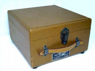
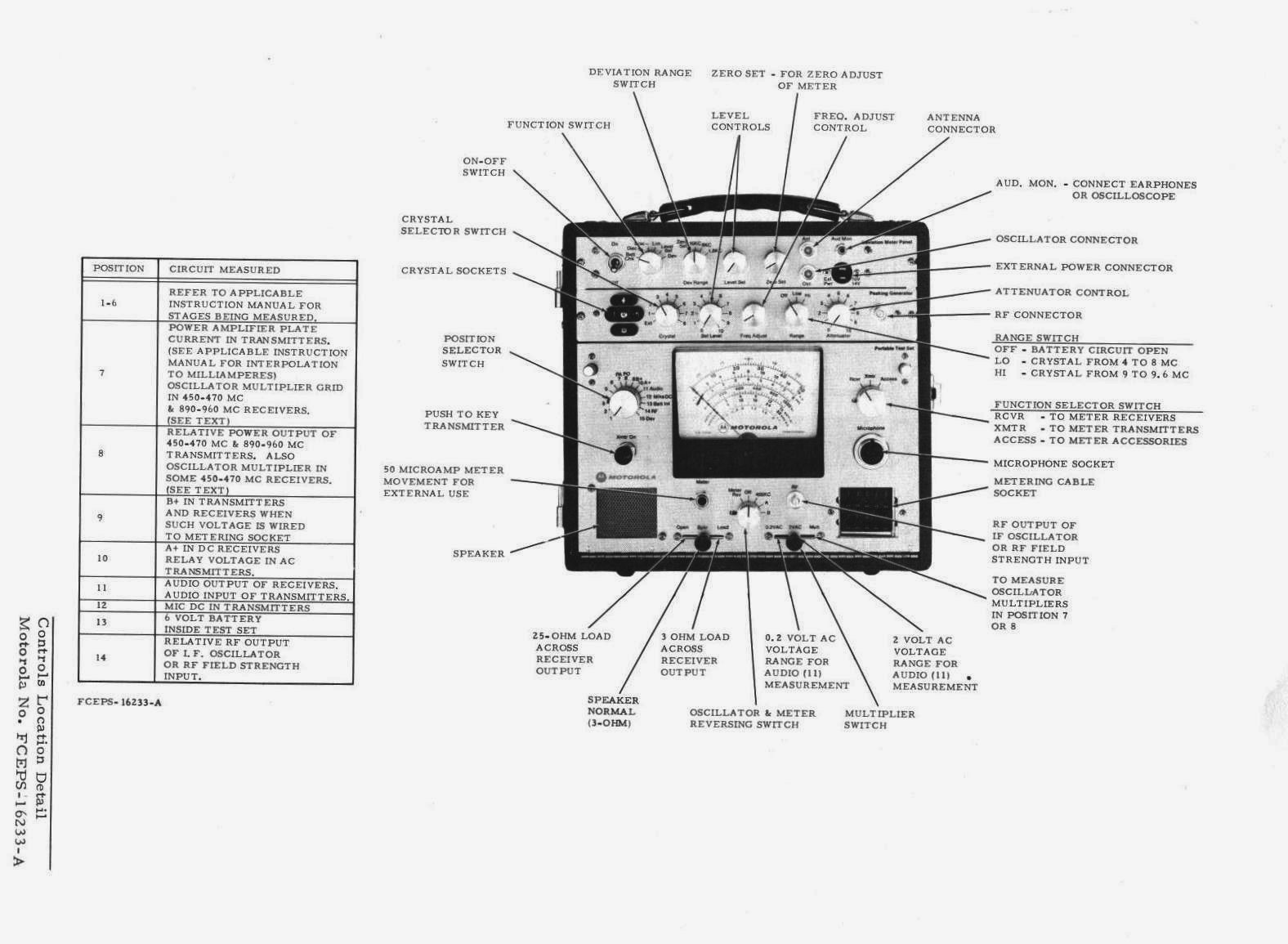
The Motorola "Portable Test Set" has gone through several generations. Besides being portable in the sense that a lunch pail is portable, it was never designed to be actually used on portable radios (there were / are specific test sets available for that).
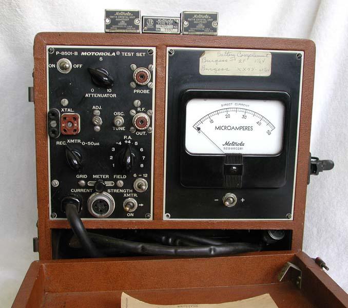
The original test set was the P-8501. This unit was built / used in the 1950s and into the mid-60s. This test set has/had a vacuum tube-based crystal oscillator which could be used as a signal source to set receivers on frequency. Note the crystals from the era lying on top of the test set in the second picture. The unit has a "attenuator" control but it wasn't an atenuator as we think of it today, the control only varied the screen voltage on the oscillator and RF amplifier tubes. Some field mods were developed to provide a lower level signal, most lowered the the oscillator or RF amplifier plate voltage but the circuit became unstable if the voltage went too low. Other field mods added an attenuator after the RF amplifier, but most of them had too much RF leakage.
Speaking of leaks, the filament and plate circuit btteries frequently leaked, and more than one of these sets are junk due to battery acid eating away the guts. One major design flaw was that the metering cable was wired into the test set, and the point where it met the front panel was a regular failure point from excessive flexing and the resulting breaking of the copper conductors in the cable. A common mod was to put a socket into the panel and a matching plug on the cable (see the photo below of a modified test set). One common problem was that on many service calls the receiver or transmitter chassis that might be under test was at any height from ankle height to shoulder height, so a common homebrew item was an 11-pin extension cord since the test set would be sitting on the floor. Another common homebrew option was a steel rod hook that hung the test set from the top of the cabinet door or the overhead cable tray at a repeater site.
I used one of these test sets for years on tube-type mobiles and stations, made my own adapter for Motracs / Motrans from an 11-pin socket and a 13-pin relay that I gutted, cut one pin off and wired a cable into, and finally gave it all away after I picked up a TU546-series unit that came complete with the 11-pin test cable, a real Motrac / Motran cable and a real MICOR cable kit.
Click here for a 64 MB ZIP file of 15 photos (each 4-5 MB) of the outside and inside of a P-8501 test set courtesty of Shawn Rutledge KB7PWD.
Courtesy of Jim Conrad W8MQ we have a 880 kB PDF of the real P-8501-A Test Set Manual part number 54891690-B (no, that's not a typo, it's one of the few manuals that start with something other than 68).
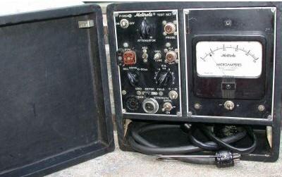
This one had to have been a field paint job... and if you look carefully the owner
punched the panel and added a 11-pin socket so the metering cable could be plugged in.
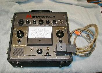
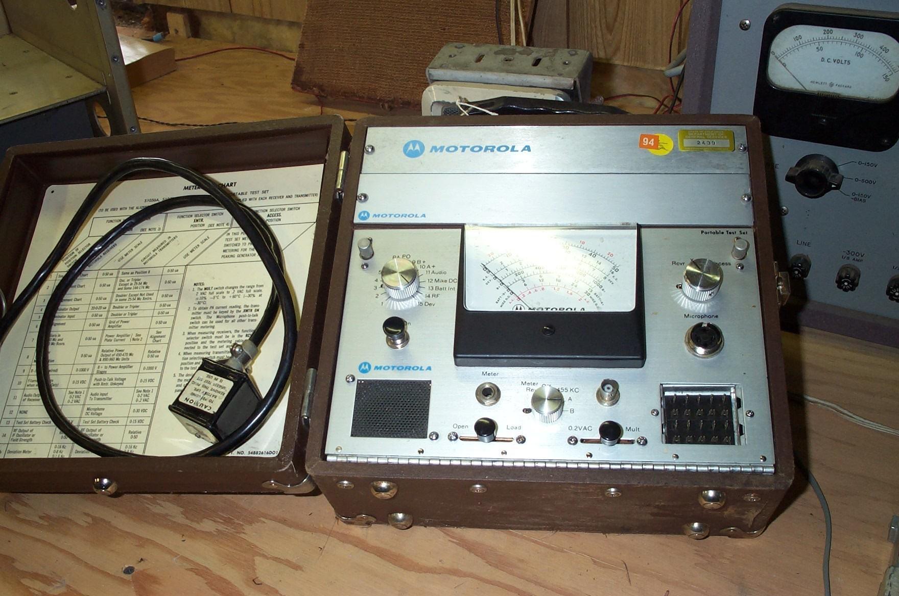
The TU546 series:
The "greyface" units were the follow-on models to the P-8501 unit. The TU-series had
a front panel connector for the radio cable (finally), but it was a special connector
made by Cinch-Jones corp. The only source of the mate was Motorola at an outrageous
price (in 2002 I was charged over $60 for the (part number 0900855269) 20-pin connector,
shell and cable clamp kit).
NOTE: Think SEVERAL times before taking the
test set cable connector apart! It falls apart into a bunch of pieces and is a major PITA (pain
in the rear) to put back together ! You will wish that you had three, if not four hands.
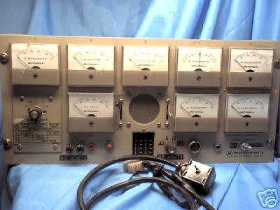
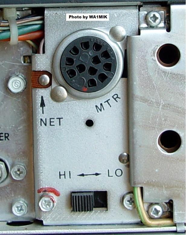
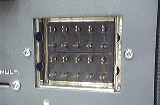
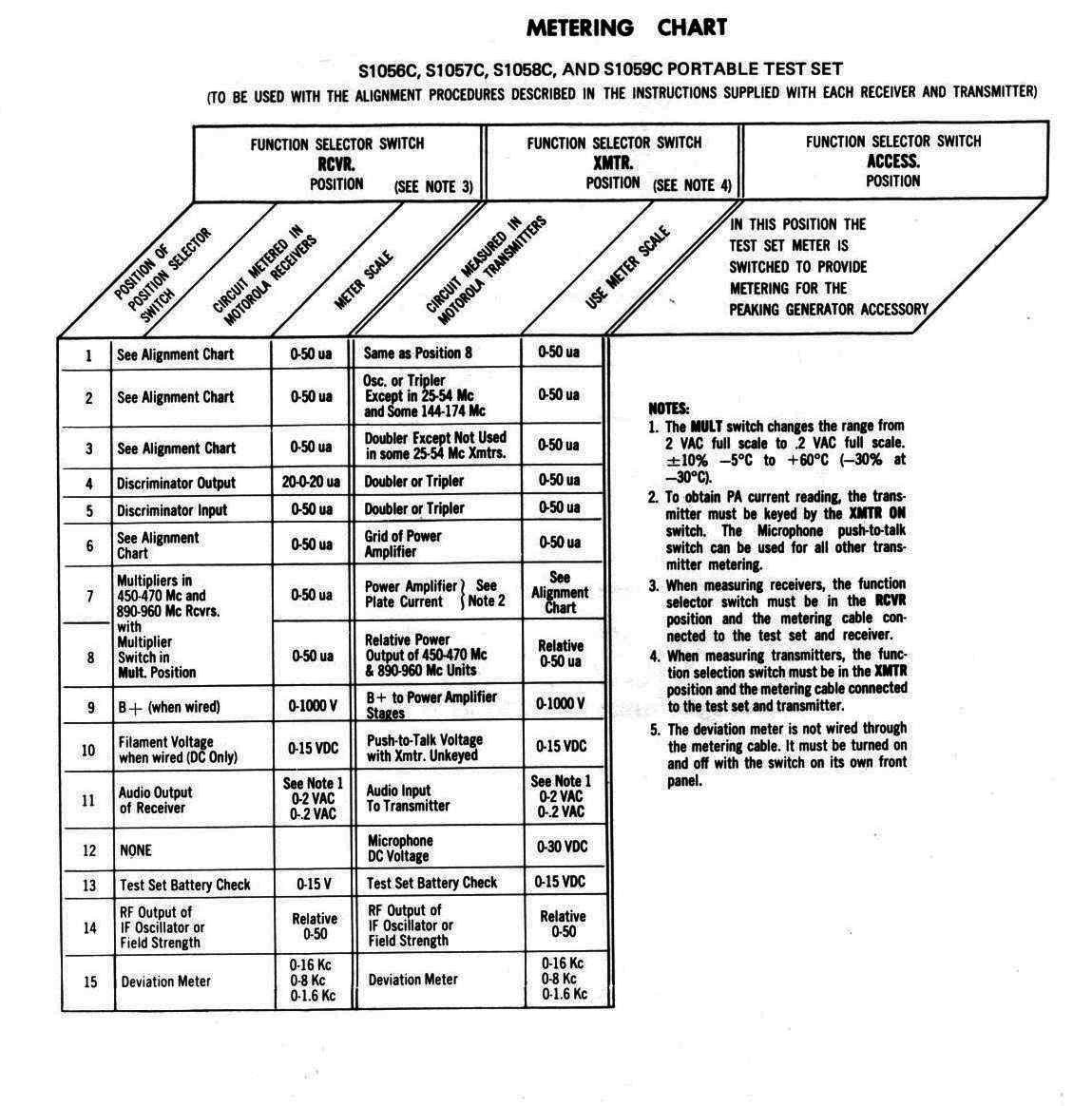
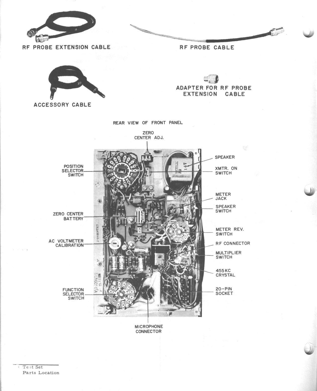
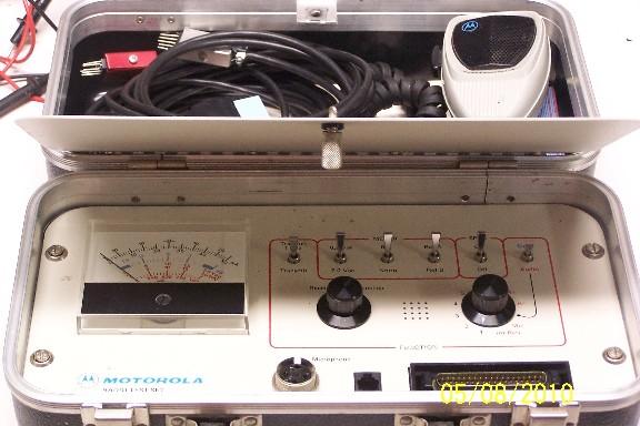
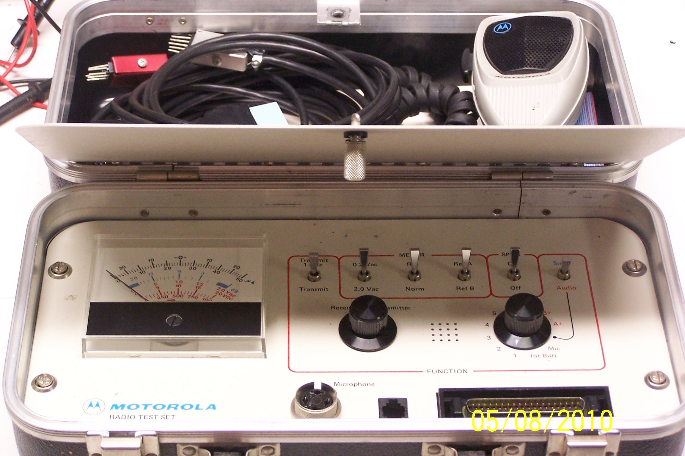
The cabinet of both the TU-546 series and the later S1056 / 1057 / 1058 / 1059 "silverface" test sets was designed for up to two options to be added - your choice of an audio generator, a peaking generator (equivalent to the crystal oscillator in the P-8501) and a deviation meter. Both the greyface and silverface test sets have an internal generator, and came with a 455 kHz crystal and had two open sockets. Two additional crystals in the range of 290 kHz to 13 MHz could go into the test set generator, and crystals from 14 through 960 MHz went into the peaking generator. The manual for the TK589 peaking generator can be found here as a 321 kB PDF file courtesy of the scanner of Eric Lemmon WB6FLY (SK).
How to ruin your test set:
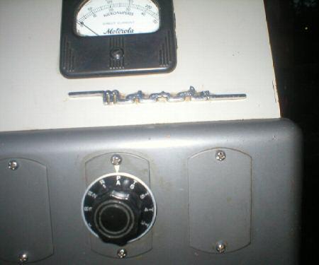
Both the greyface and silverface test sets were powered by four 1.5v "D" cells in series
plus one 1.9v mercury "N" cell - and the "N" cell is buried inside
and EVERYBODY forgets about it (there is a photo linked down further on this page in the
S1056 section that shows you where it is). The "N" cell is only used in the
TU546 and the later silverface test sets, and is only used in receiver metering position
4 to bias the meter to simulate a zero center scale meter. Moto slipped up in the initial
design by not having a "Transit" or "Off" position on the rotary switch, or at least
adding a note on the front panel to the effect of not leaving the switch in position 4
when not in use. I have seen more test sets ruined by leaky "N" cells than I
want to think about (I saw one test set where the owner relocated the zero center
adjustment pot to the front panel, took a piece of dowel the size of the "N"
cell, pushed two brass thumbtacks into the ends as contacts, soldered a piece of zip cord
to the thumbtacks, put the dowel into the "N" cell battery holder, and fastened
a "C" battery holder in the cable storage area to hold the replacement for the
"N" cell). The "power switch" for the four "D" cells is implemented as a jumper
in the 20-pin metering cable connector (pin 19 to pin 20), so by simply removing the
cable turns off the 6v battery. In addition to the four "D" cells and the "N"
cell the deviation meter option had its own internal power supply (a pair of 6.5v
mercury batteries).
So add a label to the unit saying something to the effect of:
|
By the way, the mercury "N"cells are no longer available.
The actual TU546 test set manual, part number 68849845-A is here as a 20 MB PDF file, courtesy of Marvin Moss W4UXJ. The schematics are segmented for printing on 8.5x11 inch paper. Eric Lemmon WB6FLY (SK) scanned his copy of the same manual in a full width mode and offers it here as a 2.3 MB PDF file. Both files have the information on only the test set and the peaking generator. The audio generator and deviation meter options had their own manual and I do not have a copy of either one. Marvin's PDF file has the extremely rare Moto-authored mod sheet (starts on page 44 of the file) on adding the capability of metering GE radios of the era to it. Those pages are available separately here as a 3.6 MB PDF file. Eric's file is a full width scan, you will want to put the file on a USB flash drive and have the wide pages printed on a roll feed printer somewhere (see the GE LBI index page at this web site for more comments on printing full width PDFs).
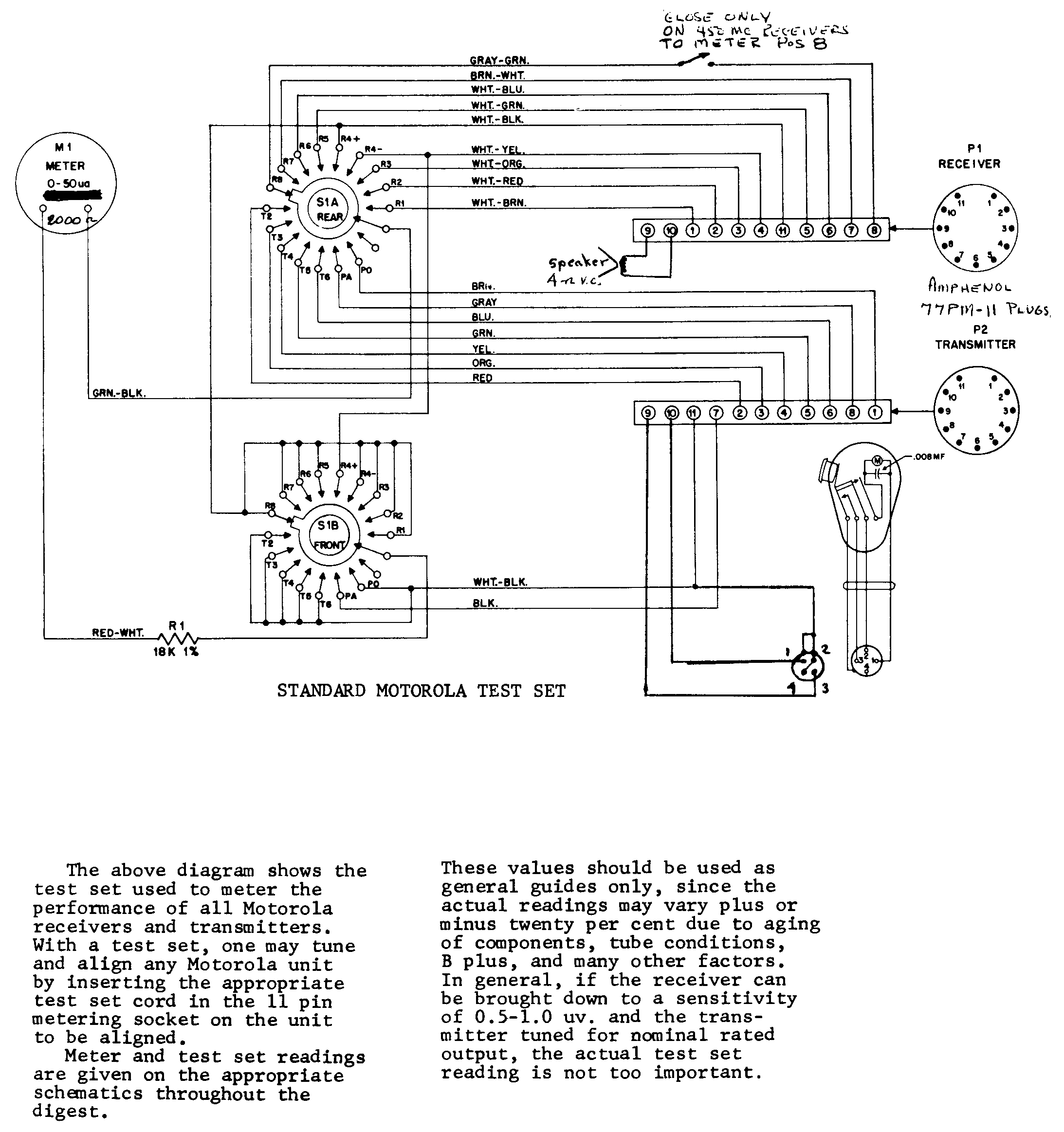
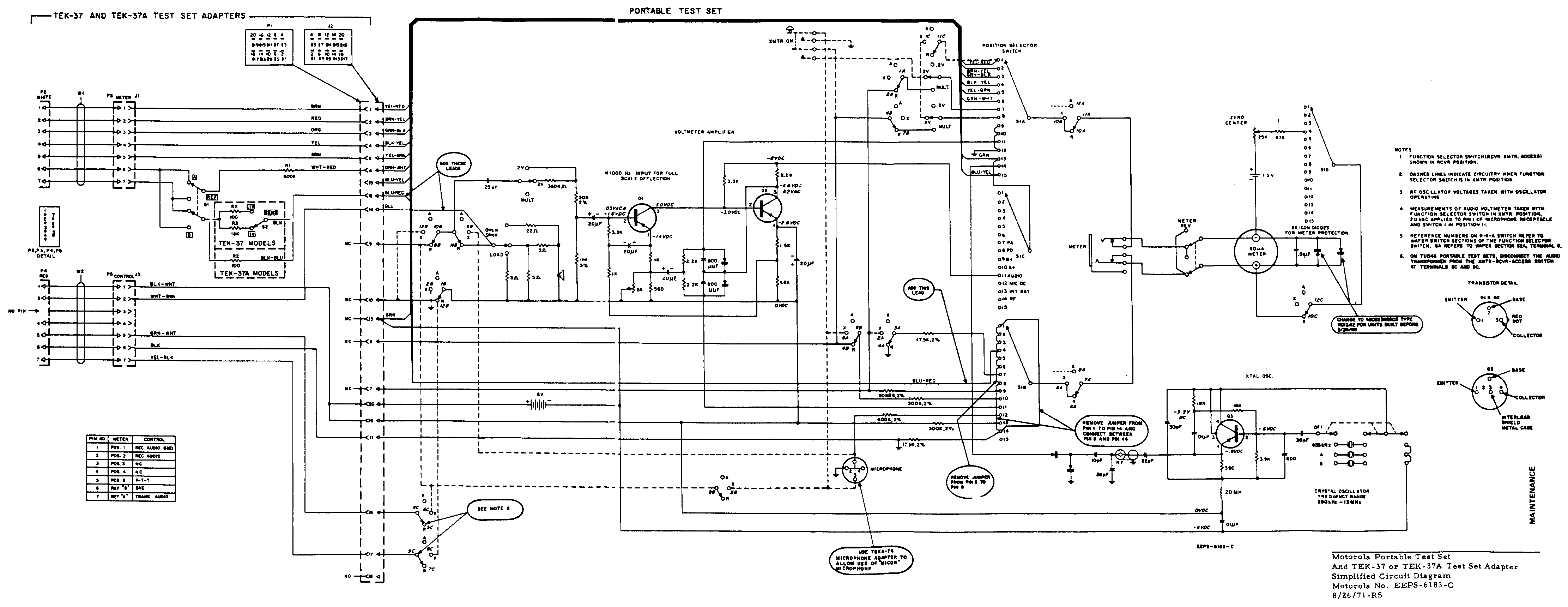
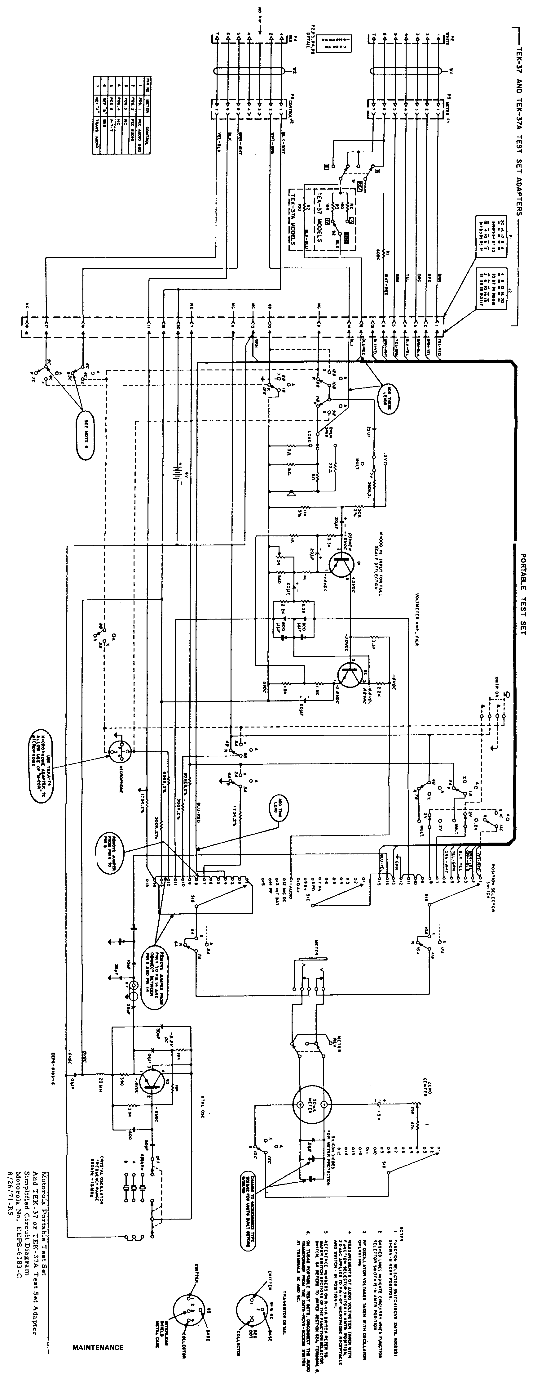
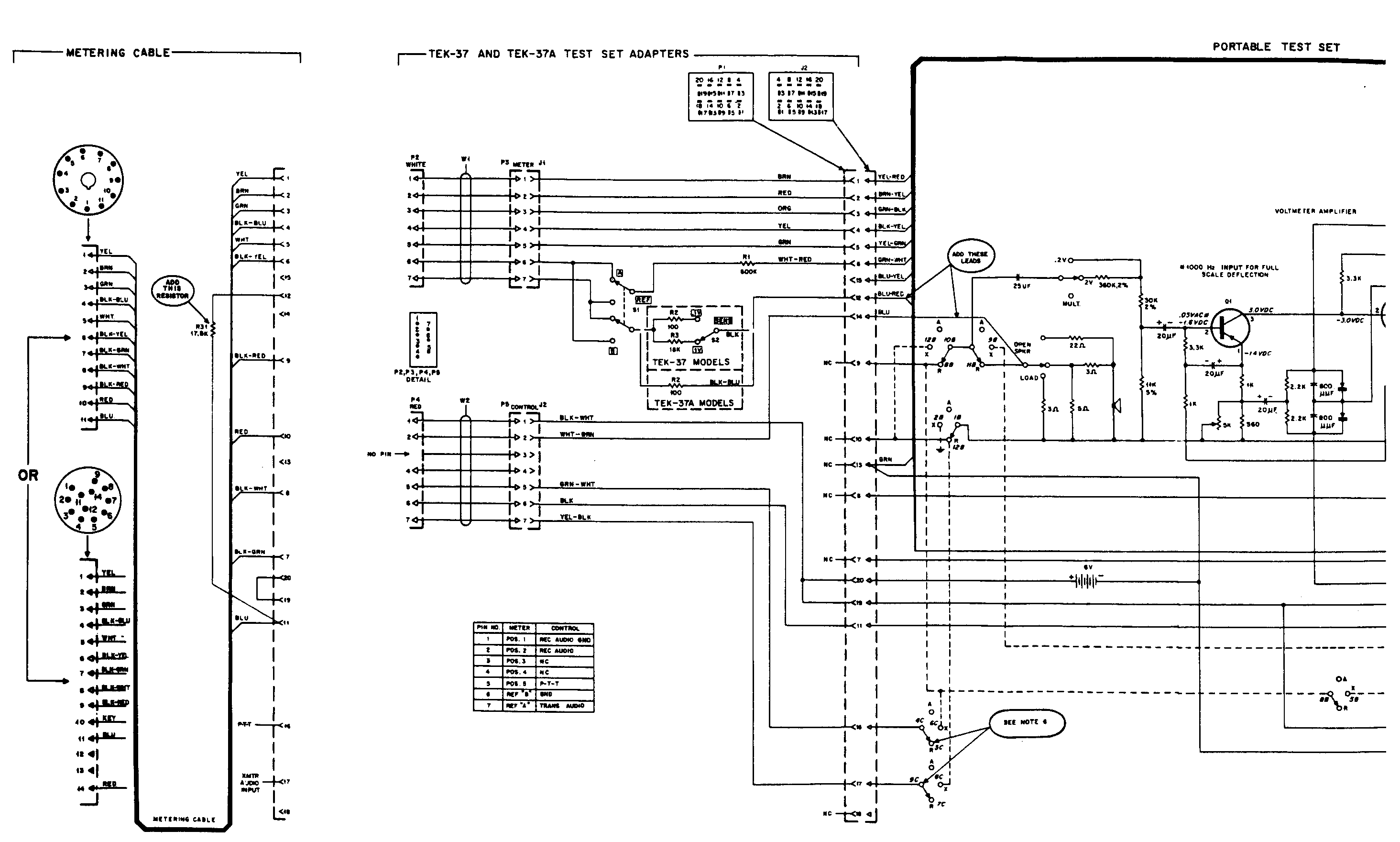
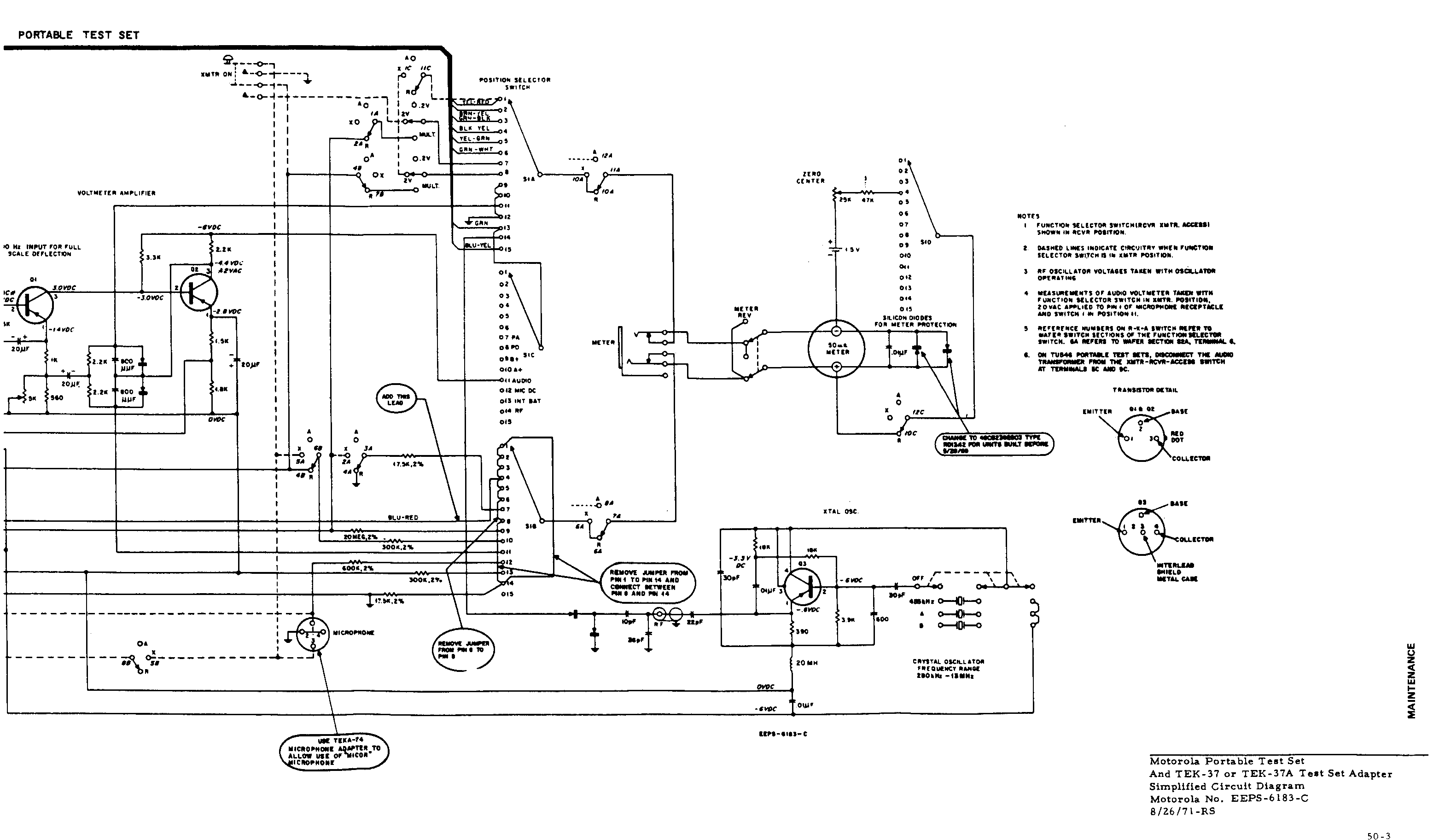
Here's the Moto portable test set schematic by itself:
Horizontal format (for viewing)
Vertical format (for printing)
This schematic is probably for the late TU-series greyface or for the S-series silverface
test set as it shows the MICOR adapter and wiring mods. The diagram is a large
format file - you will probably end up printing it on multiple pages and taping it
together, or see the above comments about printing wide sheets.
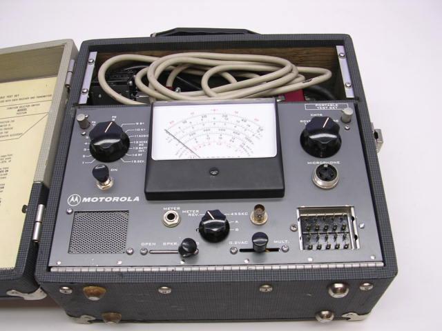
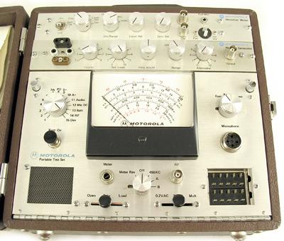
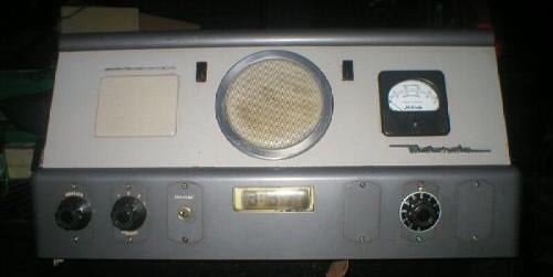
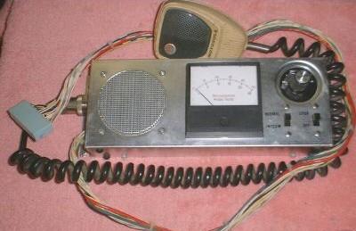
The deviation meter option depended on the peaking generator being there already. The
owner of the test set in the upper photo used the option space to store metering cables
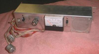
and a microphone. The test set in the lower photo below has the peaking generator option
installed, and the MICOR test cable plugged in. The peaking generator has a multiposition
switch (the leftmost one in the photo) to select any one of several internally installed
crystals or the front panel sockets (for three different sizes of crystals), all in parallel.
While not technically a "portable" test set, the TEK-5 model uses the same cables as the
TU546 test set above. It has one meter for each of the most popular metering positions
and was absolutely invaluable for spotting interaction between metering positions.
The first one I ever saw was bolted into an early service truck, with a 140-D mobile
cabled to it. Here's a photo of the TEK-5C version (probably from an ebay auction):
We also have a manual for the TEK-5 as an
813 kB PDF file.
Here's documentation for a meter
reversal switch conversion kit for the TEK-5E as a 29 kB PDF file.
Here's documentation for the TEK40
(MICOR metering) conversion kit for the TEK5B or TEK5C as a 775 kB PDF file, which is
installed in the meter shown above.
Test Cable Numbers:
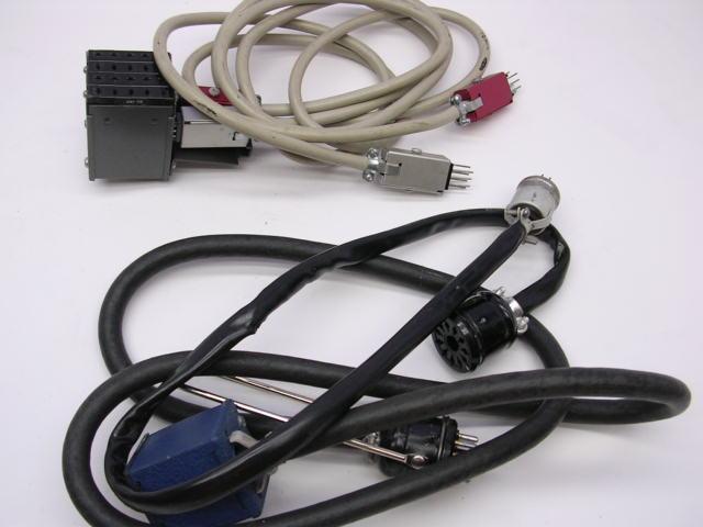
The above photo shows the three most common cable kits...
|
|
Not shown is the common homebrew 5 to 6 foot long 11-pin extension cord. It is made up of the raw bulk test set cable (part number 3082020H01), plus a set of 11-pin connectors which are no longer available from Motorola, but are available from Heath and Collins enthusiasts, or on eBay. | |||
|
|
The SKN6013 cable is the original tube type radio cable - it has the 20-pin test set plug (painted blue in the photo above) on one end and the male 11-pin octal style plug on the other. The documentation on it is in the test set manual. In the photo above it starts at the blue plug and ends at the 11-pin octal style male that has the chrome-plated pull rod attached. | |||
|
|
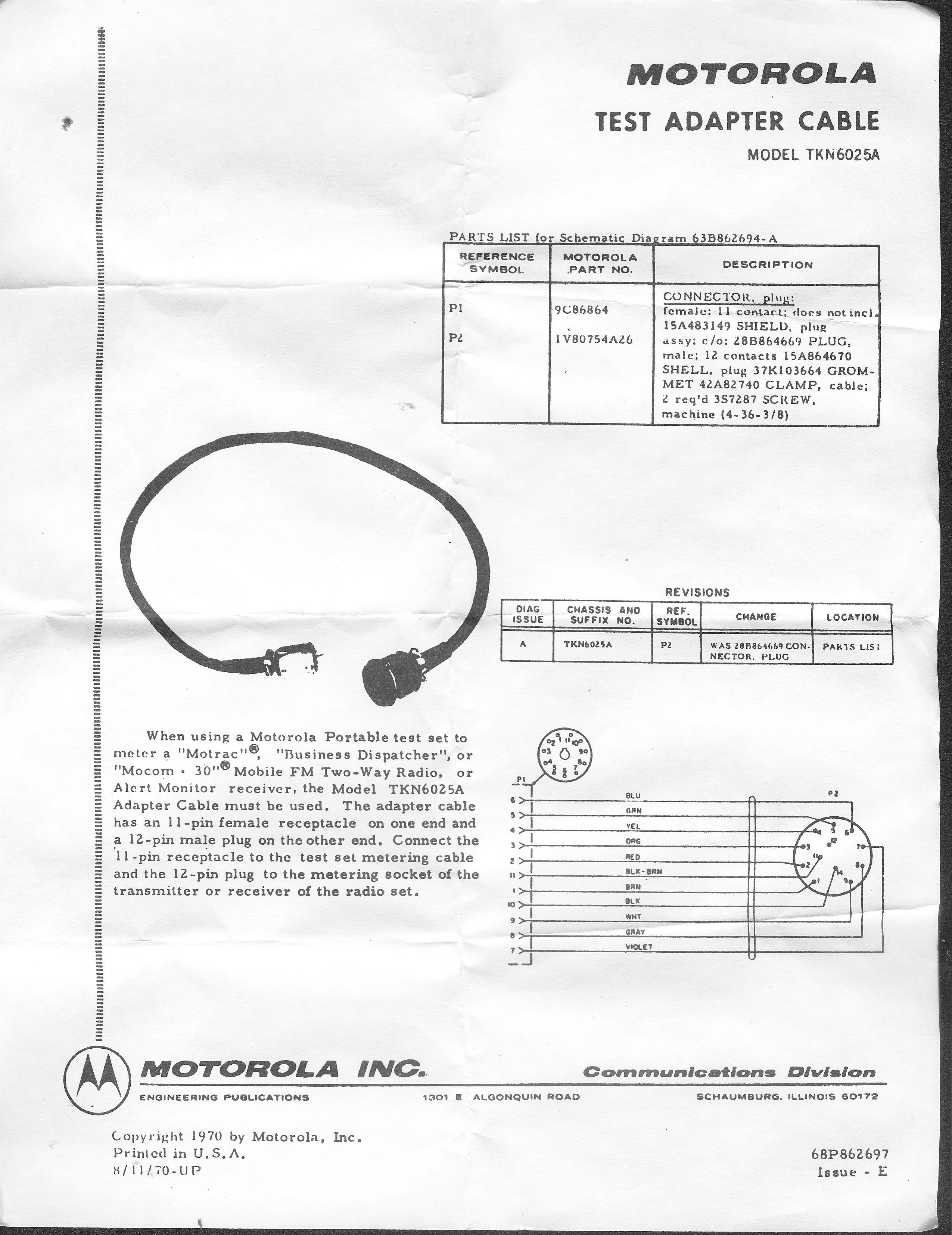
The TKN6025 cable is the adapter cable for the above cable. It has the female
11-pin octal style plug on one end and the 12-pin miniature plug (for
Motrac / Motran / Mocom / Mitrek radios) on the other.
In the photo above it starts at the 11-pin female octal style socket and ends at the
aluminum cylindrial plug. The "manual" on the TKN6025A is a single page schematic
and parts list 68862697-E. This scan is courtesy of Tom
Gunderson W9SRV. A much smaller file (45 kB PDF) was supplied by Eric Lemmon WB6FLY. A slightly older version of the manual (76 kB PDF) was supplied by Eric Lemmon WB6FLY. |
|||
|
|
The SKN6012 cable has the 20-pin test set plug on one end and the 12-pin miniature plug on the other - it replaces the combination of the above two cables. In mid-2006 the price on this cable was about $130. The "manual" on this cable is 6881120A22-B as a 99 kB PDF file. | |||
|
|
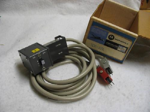
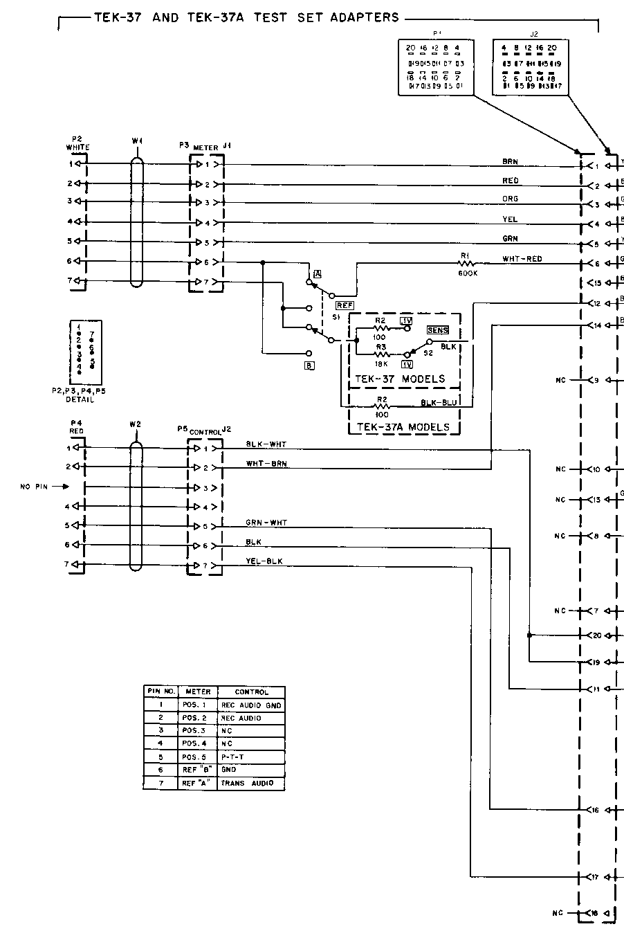
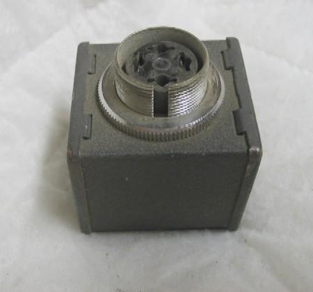
The TEK37 series cable kit (at the top of the above photo and is also visible in the lower photo of the TU-series test set) allows the test set to be used on MICOR radios. It is made up of one plug assembly that plugs into the test set plus two TEKA72 cables. Here's a photo of a fresh-out-of-the-box TEK37A, and the lower of the two TU-series photos above shows it plugged into the test set. The TU-series and the early S1056 / 1057 / 1058 / 1059 series test sets must be modified to work with the MICOR kit (the mod simply adds MICOR functionality without affecting anything else). The documentation on the TEK37A MICOR cable kit is 6881121A01 as a 438 kB PDF file (scanned by Eric Lemmon WB6FLY). The cables used in this kit had their own part number (TEKA72A) and their own "manual", the 6884258C53-A as a 168 kB PDF file. That "manual" was later reissued as 6884258C63-A as a 131 kB PDF file and is a much clearer scan (courtesy of Eric Lemmon WB6FLY). The original TEK37 had a two position switch that controlled the voltmeter sensitivity, the later TEK37A dropped the switch. Here's a schematic of the TEK37 showing both versions. You can add a SPDT switch and an 18 K resistor to a TEK37A to get the TEK37 functionality if you want to. | |||
|
|
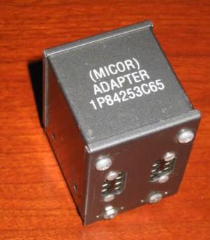
An early version of the TEK37 was the 01P84253C65 adapter. If anyone has a copy of the writeup we can scan please let us know. | |||
|
|
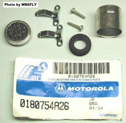
If you have an extra cable (perhaps the 11-pin tube-type radio cable) and you want
to convert it to match the type of metering socket that was used on the Motrac, Motran,
Mocom-30, Mocom-35, Mocom-70, Mitrek, and several other radios then you need to order
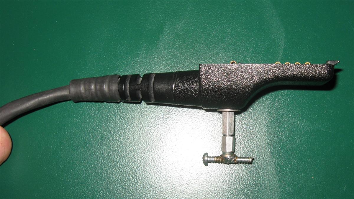
a plug kit. The metering socket photo is by Bob Meister WA1MIK (SK).
The complete plug kit is part number 0180754A26 and it will set you back about US$17 to $18.
Don't lose one of the two screws shown in the photo, they are a weird 4-36 thread and impossible
to find (the voice of experience). The plug kit photo below is courtesy of Eric Lemmon WB6FLY:
|
|||
|
|
The TEK19 is a square plug adapter that plugs into the test cable connector and tests any of the round-plug microphones from the Motrac / Motran / Mocom series. Here's a photo of a TEK19. Simply plug the TEK19 into the test set, plug a microphone into the connector, squeeze the PTT and talk into the microphone. If the meter peaks at over some magic value, the microphone is good. Unfortunately I don't have any literature on the TEK19 so I have no idea what the magic number is... Various adapters / adapter cables allow testing microphones that have other connectors (MICOR / Syntor / Mitrek / MaxTrac / Spectra / etc). Does anybody have a copy of the Motorola info sheet or manual on the TEK19? We'd like to scan it. We'd also like photos and literature of the other microphone plug adapters. | |||
|
|
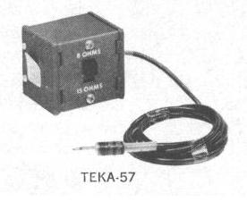
The TEKA-57 Audio Metering Adapter looks like a TEK19 and it
plugs into the greyface or silverface metering sets. It has a two conductor cable with a
1/8 inch / 3.5mm diameter mono plug and can present either an 8 ohm or a 15 ohm
load to the speaker audio circuit of the radio under test. It was used to measure the audio output
from a handheld for 20 dB quieting checks. The audio load inside the plug is made up of two 15 ohm
1/2 watt resistors, one is used in the 15 ohm switch position, two in parallel make up the
8 ohm position.
One comon repair (modification ?) was to replace the first one with a 5 watt resistor since most
mobile radios of the day had enough audio power to smoke the 1/2 watt resistor.
The "manual" on the TEKA-57 is
68B8111A52-A as a 544 kB PDF file. The TEK17B was a similar unit but with two slide switches on the top. Does anybody have a copy of the Moto info sheet on the TEK17B? We'd like to scan it. We'd also like a better photo. |
|||
|
|
The TEKA74 adapts a MICOR microphone to a round-plug (i.e. Motrac / Motran / Mocom) environment such as a TEK19, TU546 or S1056. A microphone test only uses three wires (PTT, ground and audio) so building an adapter for other Moto microphones is easy. Does anybody have a copy of the Motorola info sheet or manual on the TEKA74? We'd like to scan it. We'd also like a photo. |
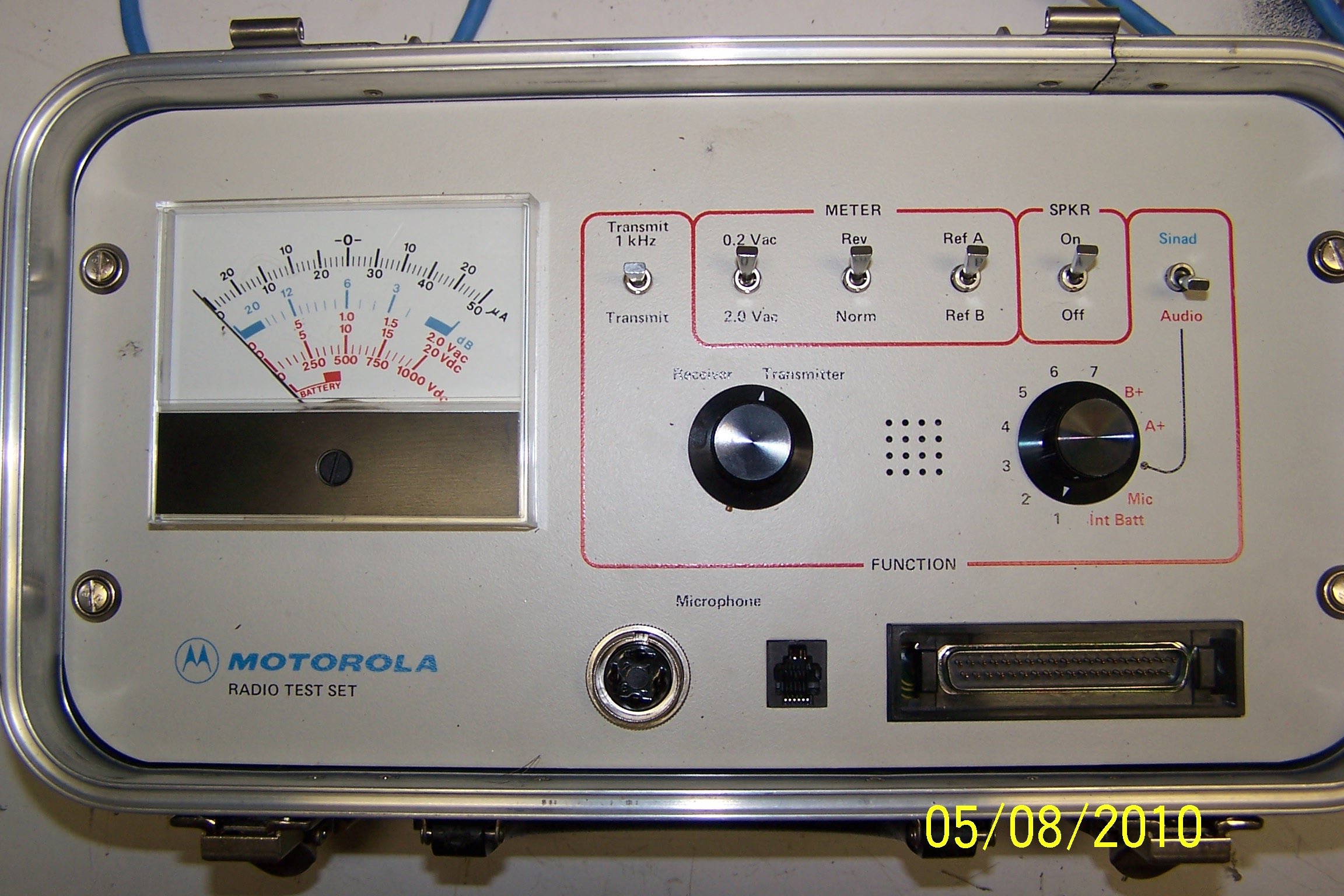
The S1056 / 1057 / 1058 / 1059
series:
The "silverface" test sets were the follow-on models to the TU-546 units. They are
pretty much just a cosmetic update and as such all of the TU-series test cables will
work on the S-series test sets. The major electrical difference is that test sets
manufactured after 31-December-1969 left the factory with the MICOR mod already
installed.
The silverface test set also has the "forgotten N-cell" problem mentioned above, so make sure you add the warning label mentioned in the greyface section above.
By the way, the real S1056 / 1057 / 1058 / 1059 test set
manual is part number 6881011A01
as a 4.6 MB PDF file, at around $5 (2005 prices), however last I heard they were out of
them and not planning to reprint them. But if you are calling Moto parts for something
else it doesn't hurt to ask.
Another version of the
same manual can be found here as a 4.6 MB PDF file.
A color/gray version of the
same manual can be found here as an 8.1 MB PDF file.
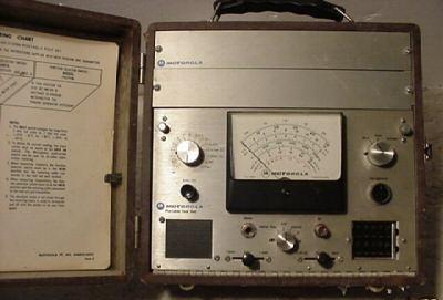
More S1056 info:
The schematic:
Schematic Left Side
Schematic Right Side
The extreme left side shows the schematic of the 11-pin octal-style and Motrac / Motran / Mitrek
cable and of the MICOR cable.
A diagram of what switch does what....
A scan of the chart that goes inside the cover
If yours is missing you will want to print this, then have it laminated
A scan of a page from the manual showing
just where the infamous "N" cell is located Look for the words
"ZERO CENTER BATTERY" on the left side, then follow the arrow.
The above files were from WA6ILQ's file cabinet.
|
|
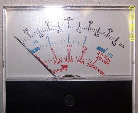
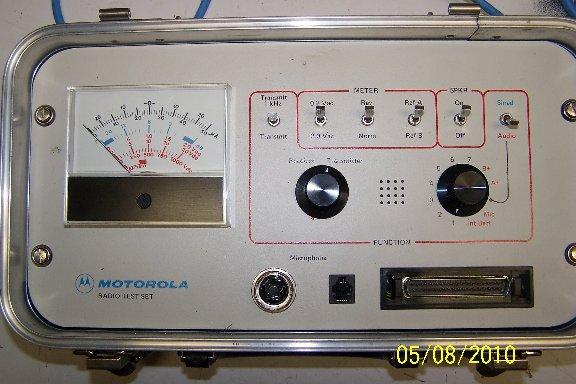
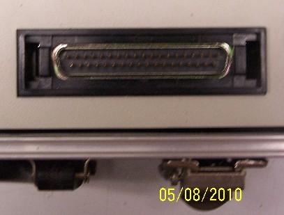
The R1033 / RTL4118 / RTL4119 Test Set Series This was a follow-on to the S1056 / 1057 / 1058 / 1059 series. Besides being a complete ground-up redesign, it has several nice features including a built-in SINAD meter (this test set was the first Moto set to have a SINAD quieting measurement as well as a 20 dB measurement). It also has enough room in the lid to store several cables (if you had both option slots in a TU-series or an S-series test filled you had room for only one cable in the lid...), a built-in audio generator, and it uses common DB-37 cable connectors. Another feature is that the PTT switch has the option of sending a dead carrier or one modulated with an audio tone. There is no battery on/off switch - like the TU-series greyface and S-series silverface sets the battery is disconnected when the metering cable is unplugged. It's apparent that Moto learned at least three lessons from the older greyface/silverface sets, the first is evident in that this design has a single common 9v battery, that the battery is easy to change and there is a meter position to read the voltage of the internal battery (see this closeup photo of the meter) (by KE4QKI). Still, do yourself a favor and put a label on the front panel, perhaps above the meter, with a note as to when the battery was last replaced, then change it every year, no matter if it needs it or not. If the test set is going into storage for a while, remove the battery. The internal speaker leaves a lot to be desired, more than one test set has been modified with an external speaker jack. The basic portable test set is the R1033, two variants on it were designed to fit into the lid of the service monitors of the day, the RTL-4118 for the R2001, and the RTL-4119 for the R2200 monitor and are simply repackaged versions with no schematic changes. Here's manual 6881069A78-C for the R1033 Smaller size, 435 kB Larger size, 1.66 MB. The smaller size may not work with some PDF readers. The large manual PDF has a little better resolution and was donated by Eric Lemmon WB6FLY. Unfortunately the manual does not contain any test cable schematics. 
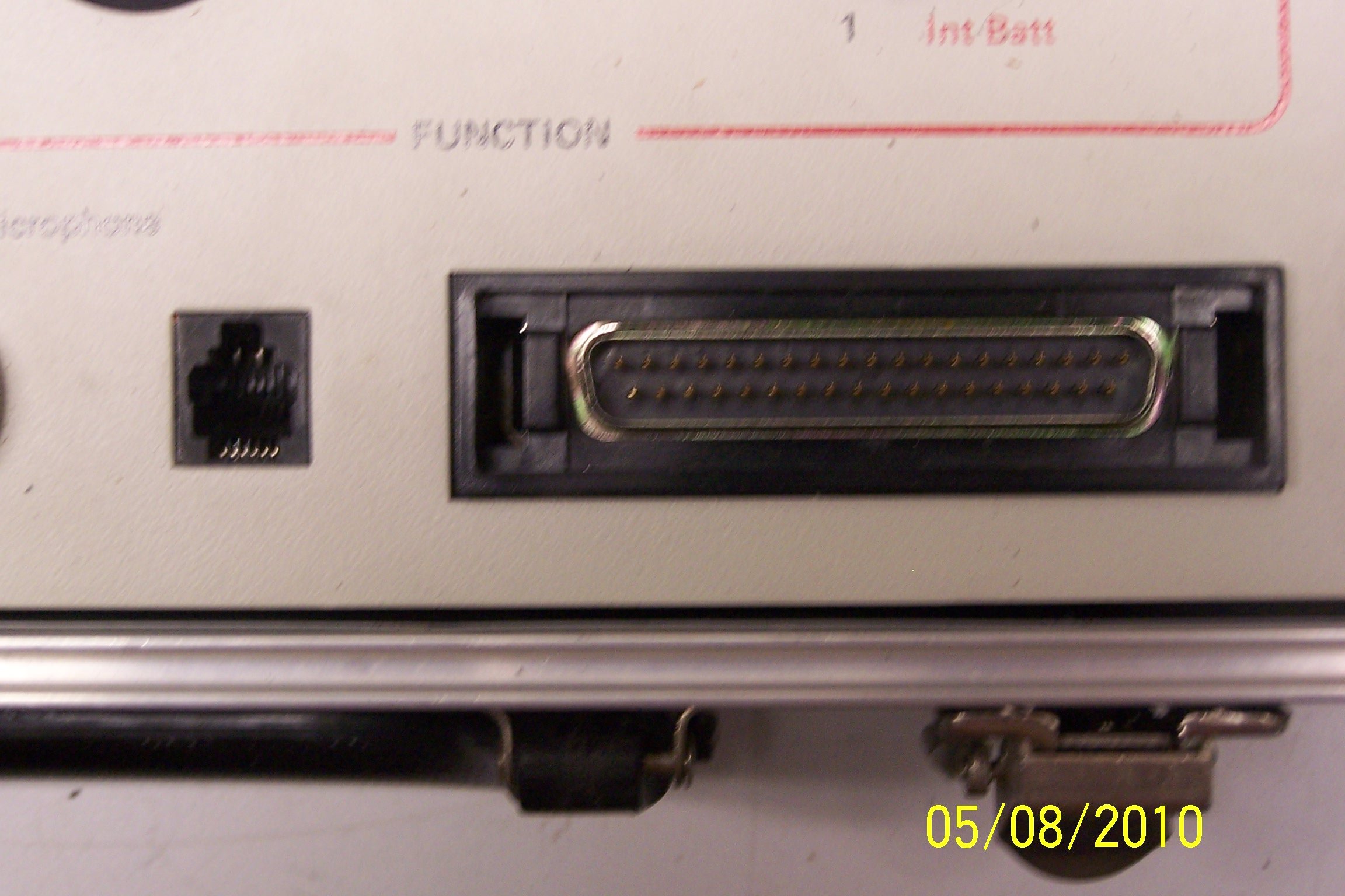
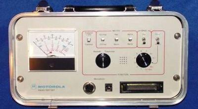 The front panel above has two microphone connectors - the round plug for the older Motrac / Motran / Mocom style microphones and the black square to the right of that is an RJ14 jack (a 6-pin RJ-11) for the the HMN1001B microphone that is more commonly found with the MSF5000 station. The black rectangle to the right of that is the common DB-37 connector for the radio test cable. The TEKA74 adapter mentioned above allows use of a MICOR microphone with the round Motrac style connector. Another adapter is used on the flat Spectra style plugs (does anyone have the part number? Or a photo and a writeup we can scan?). Here are two manual revisions for the R-1033 test set, courtesy of Jacob ADØJA, 2 MB PDF. One problem: the HMN1001B microphone (also known by the military number
NSN 5965-01-433-8086) is rather rare, and when found is usually expensive
(especially if the person knows what he has...). The price from Moto in 2008 was $105
plus shipping. A cheap equivalent is to take a cheap common 8-pin (i.e. RJ45 style
plug) microphone from a MaxTrac, Radius or GM300 and an RJ45 jack with screw terminals
(as opposed to punchdown style terminals) and a short 6-pin RJ11 silver-satin cord and
mate them. Just take the pinout of the microphone (available on the MaxTrac/Radius/GM300
page at this web site), the the schematic from
the data sheet of the TMN6164A test handset made for the MSR5000, which includes a
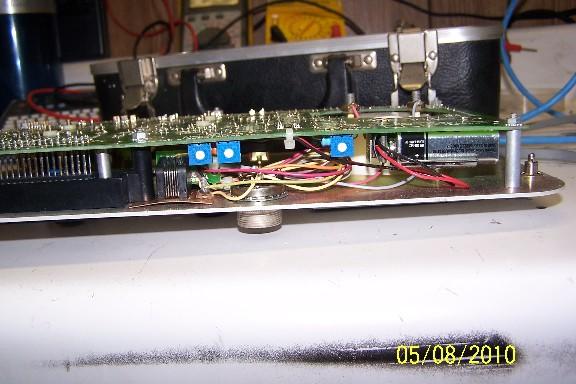
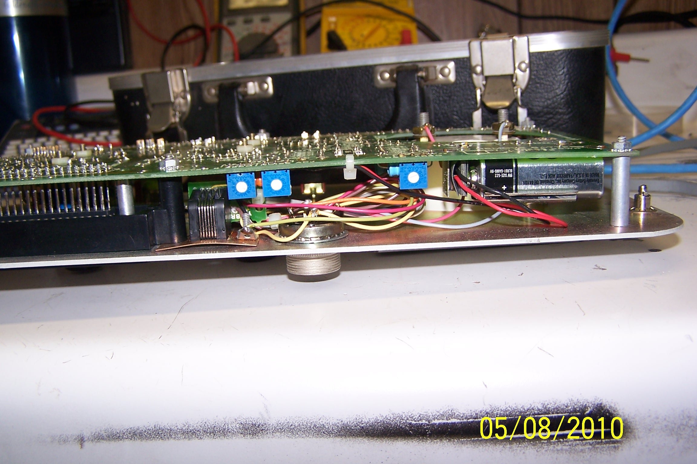
nice connector pin-out table, and make yourself a microphone adapter cable. Here's some interior photos of an R1033 courtesy of Anthony Stump KE4KQI:
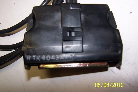
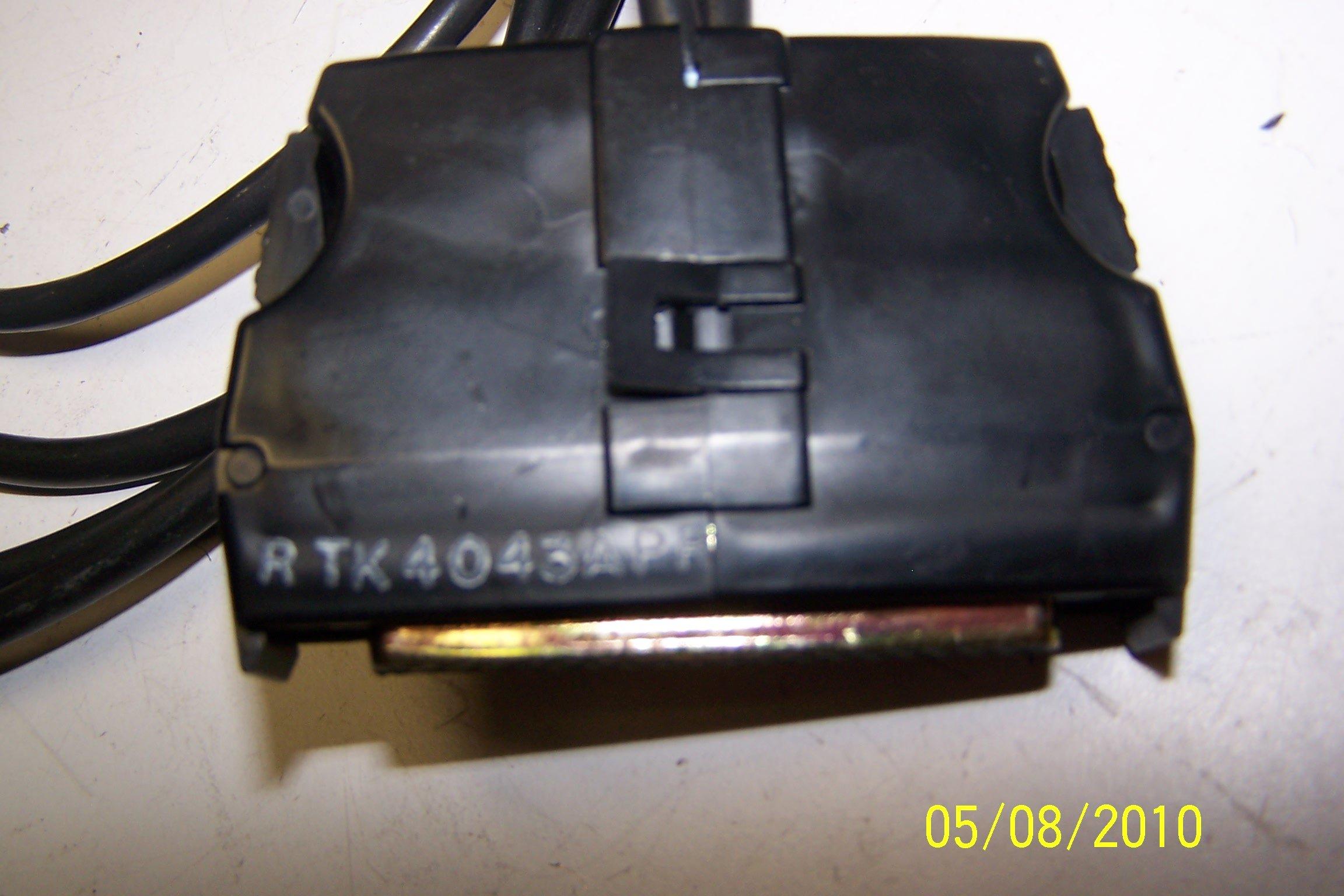
CAUTION: The R1033 has an internally grounded
speaker. The RTK4043A cable is designed to be used with a MICOR mobile. The MSR2000
uses the same metering jacks as the MICOR mobile and station. If you use that cable
to meter the test points in a MSR2000 station you WILL blow the speaker amp
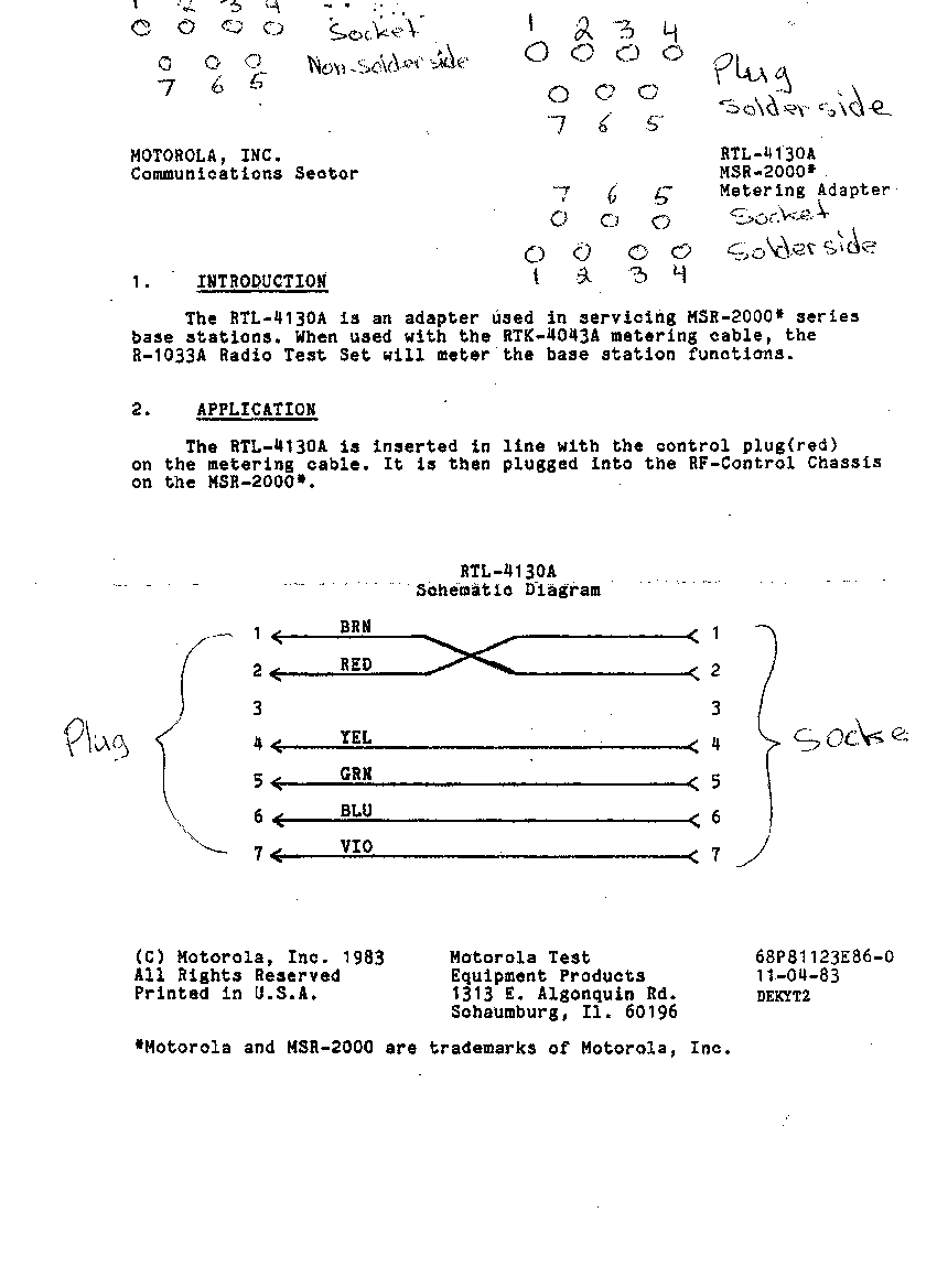
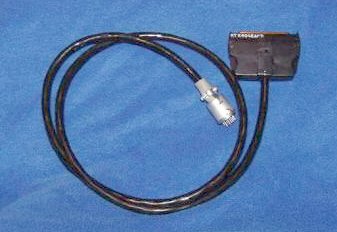
in the MSR. An adapter cable was developed to resolve that situation, the RTL4130A
(Here's the data sheet on it, courtesy of
Tony Lelieveld VE3DWI, by way of Johan Keulder ZS6CAQ). It is used in the line between
the red plug of the RTK4043A metering cable and the station. Make sure you either make
your own RTL4130A adapter (all it does is swap pins one and two in the red MICOR
connector), or modify your RTK4043A cable to match it before you meter an MSR. I've
seen modified RTK4043A metering cables that had a subminiature DPDT switch in the DB-37
housing that swaped pins 2 and 15, and a label on the switch that said "MICOR Mobile"
in one position and "MSR2000 Station" in the other. The test set had a a label on the
front of the R1033 saying "WHEN METERING THE MSR MAKE SURE YOU SET THE SWITCH ON THE
METERING CABLE PROPERLY" or something like that. Or you could make yourself a duplicate
of the RTK4043 cable kit, with the two pins appropriately swapped, and label the
unmodified cable as "MICOR, Syntor, Syntor X, Syntor X9000 mobile radios" and the
modified one as "MSR Station Only". Remember that Murphy was a ham, and make the labels
in flourescent pink or something else that's just as obnoxious.
R1033 Cable Information: (if anyone has cable schematics, other
paperwork or can take photos of the things that are missing photos please let
repeater-builder know).
|
|
|
Manual
6881069A77-O for the Model R-1034A Control Line Test Set 720 kB PDF
file
Note that the R-1034A Test Set and the R-1034B Control Line Test Set are two very
different products inside despite the fact that they have a similar purpose. Many dispatch systems had the base station or repeater at one location and the control point at another. Setting up or maintaining the connecting phone line required the ability to make both DC and AC measurements. Motorola and Triplett together designed the Model R-1034A Control Line Test Set, and the mixed background of the Motorola 2-way engineers and the telephone telecommunications background of the Triplett engineers shows in the design. This unit is essentially a specialized AC and DC VOM and an audio generator all in one ruggedized package (they used the existing housing from the Triplett 630 series VOM). It measures telephone line current, telephone line noise, DC resistance and both AC and DC Volts, and all measurements are using ranges that are optimized to telco control lines. This test set will also send audio tones at an adjustable level and measure received tones in dB on the meter. A pushbutton adds a 10 dB attenuator in line A switch on the lower left of the panel selects bridged or terminated mode. The unit was built into a sturdy protective carrying case with a pocket in the lid for the book and the probes, and a snap-hook shoulder strap for carrying. There is a 1 amp fast-blow fuse that is in line with the volts and ohms measuring circuitry inside the battery compartment. The test set is powered by two common 9 Volt batteries and one D cell battery - and the second 9 V battery is behind the "D" cell! Before you buy a second-hand R1034 make sure that you open it up and check for corrosion caused by leaky batteries (this is the voice of experience speaking...). 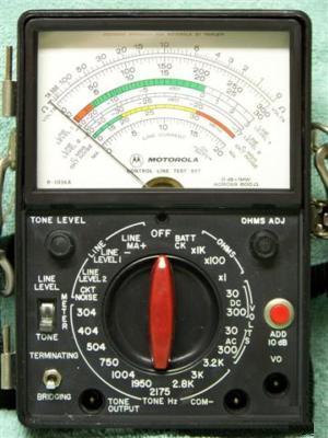 Click on the photo for a close-up of the meter panel |
|
|
Manual
6880310B60-O for the Model R-1034B Control Line Test Set 511 kB PDF file Note that the R-1034A Test Set and the R-1034B Control Line Test Set are two very different products inside despite the fact that they have a similar purpose. This is a redesigned and updated version of the above. Triplett sold this unit as the "Model 4 Subscriber Loop Test Set" for doing telephone circuits. Unfortunately, the manual for the "B" unit does not contain a schematic diagram or parts list. If anyone can turn up that info - even if it is the Triplett manual - we'd appreciate it. |
|
|
Manual 6880309B90 for the
RTX4005B Portable Radio Test Set as a 620 kB PDF file. This is a
specialty device for testing MT500, MX300, HT90, HT440, HT600, MT1000, PT500, MX
series, Expo, Saber and Astro Saber handheld radios. Manual PDF file donated by
Eric Lemmon WB6FLY. A cable from the RTX connected to the speaker-microphone jack
and allowed tapping the microphone line for injecting audio (like from a signal
generator) or tapping receive audio (for making quieting measurements while aligning
the radio). The "A" and "B" vintages of the RTX set are different, and the
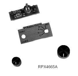
RPX4665A mod kit will field update the "A" series units
to the B revision. Here's a photo of the RTX4005A unit - note that under the blue "Motorola" logo the front panel says "MT / MX Test Set". There is a label on the bottom that identifies it as a RTX4005A. 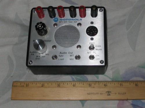 Moto made an upgrade kit for the A-version units under the part number of RPX-4665A. The right side photo shows an upgraded "A" version test set. The kit is not cheap, in December of 2006 it was about US$105. It would probably cost less to buy a "B" version test set on eBay. 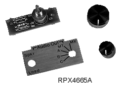
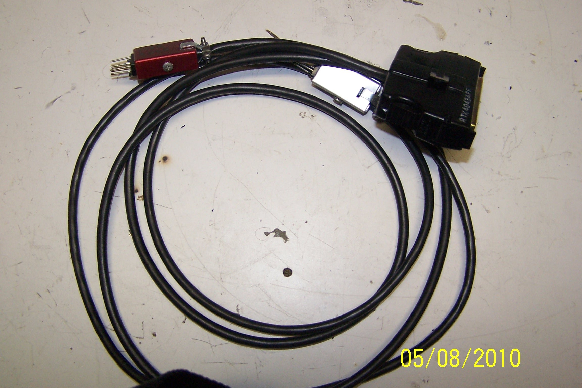
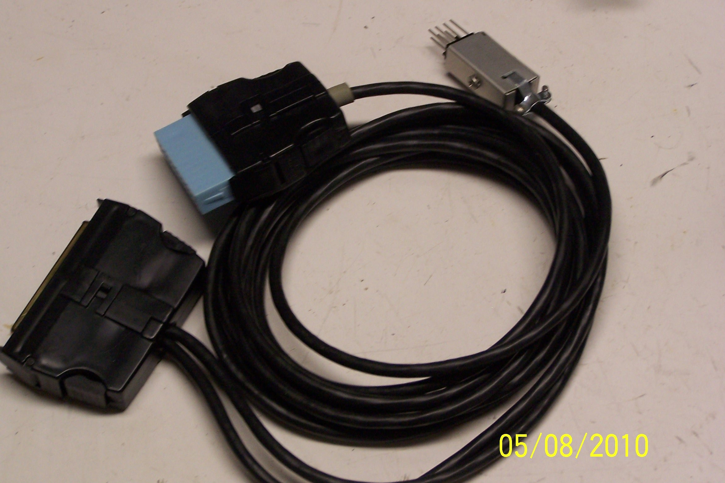
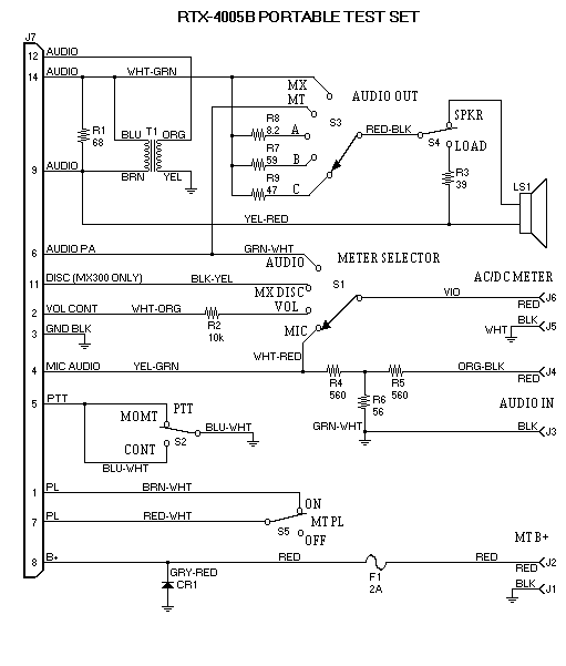
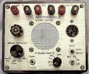 Here's a photo of the later RTX4005B. Note the front panel identity (just above the speaker). The major electrical change is the switch under the right edge of the speaker. Here's a schematic. 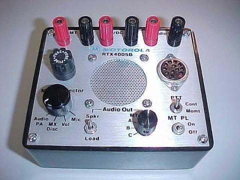 Here's two more photos of a stock RTX4005B, front and inside, courtesy of WA1MIK: 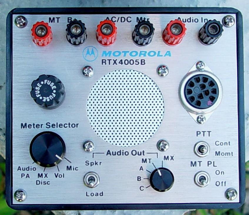 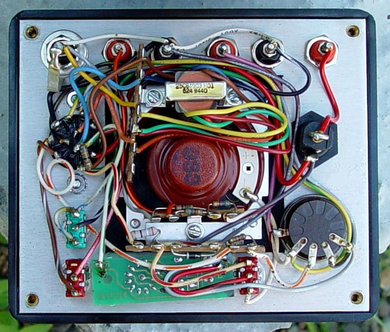 The cables made for this series test set could also be used without it as a radio programming cable - the connector that plugged into the test set had a protective rubber cap (usually green) and that pigtail could simply be ignored. If it looks familiar it's because Moto reused the connectors from the Motrac / motran / Mocom / Mitrek metering plug. The RKN4035D cable is used to talk to the HT1000/MT2000/MTS2000 series handhelds. Click here for a 358 kB PDF manual, courtesy of Kris Kirby, KE4AHR. The RTK4203C cable is used to talk to the Saber handhelds, the RKN4046A is used on the Astro Saber. Click here for a 293 kB PDF manual of the RTK4203C cable, courtesy of Kris Kirby, KE4AHR.
|
The bench-top test equipment line included "test sets" designed for specific
purposes. There was a two-tone sequential encoder made to plug into an RF generator
to test pagers, and there was the SLN6413 DPL test set shown below:
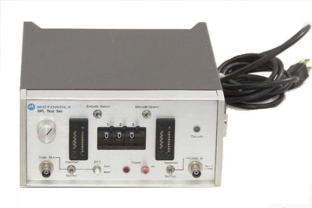
The two black rectanges (with the pin inserts) that are on each side of the thumbwheel
switch are designed for testing encode and decode plugs like the TRN6005 (which has a
how-to-make-your-own construction article at this web site). Like most Moto-designed
bench test equipment the SLN6413 can run off of 120vAC or +12vDC. There is
a power mode selector switch and a DC input on the rear.
Moto also made test sets for stations (i.e. base stations and repeaters). Here's
a scan of the schematic of an older tube-type base station metering kit - the ones
with the 11-pin octal-style connectors (scan courtesy of Bob Meister WA1MIK):
Versions of that unit were an option in the "Deluxe Line" and "Research Line"
base stations of that day, here are two photos of a late 1950s / early
1960s tabletop base:
The cabinet racks that were inside a building had a metering panel at the top
of the rack, and the outdoor weatherproof racks had an optional panel that bolted
into the rack. The manual for the TU139 optional metering kit is
68849662-H a 580 kB
PDF file, scan courtesy of Eric lemmon WB6FLY.
An earlier version can
be found here as a 900 kB PDF file, manual number 68849662-G, scan courtesy of
Eric lemmon WB6FLY.
A later series, the Motrac / Motran / Mocom-70 series stations
had a similar metering kit. Two versions were made, one designed for cabinet racks
where the meter is mounted in a meter / speaker panel in the top of the
rack (above the door). This panel was more of a swiching panel as it did not have a
physical meter. The second version was designed with a meter for the
outdoor / weatherproof rack cabinet... On both test sets one connector
pluged into the receiver chassis and the other into the transmitter chassis. The
left-most slide switch in the photo reversed the meter connections (on most Moto test
sets one receiver metering point is a "tune for zero" function), the other switch
selected either the speaker or a ten ohm resistor...
There were also metering kits made for the Motrac / Motran / Mocom-70 / Mitrek series tabletop base stations. While the were a few minor wiring differences, the main difference in the four series of metering kits was the color of the plastic panel behind the switch. Here's the manual for the Mitrek version, the HLN4138A, courtesy of Eric Lemmon WB6FLY. If anyone has the manuals for the others, please let me know.
Here's a photo of the TLN1552A metering-only panel from an early MICOR outdoor
station. It was known as Option C139, it is documented in
Manual
6881018E26-D, which covers the TLN1552A, TLN5166A, TLN5167A, TLN5168A, TLN5169A,
TLN5170A, TLN5171A, TLN5172A, TLN5173A, TLN5174A and the TLN5334A. The microphone in
the photo below was not included as part of the kit, it was ordered separately. Any Motrac / Motran / Mocom70 mobile microphone will work just fine.
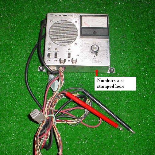
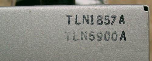
Here's the TLN1867A / TLN5900A metering and intercom panel from the later
MICOR station. If you look closely at the bottom right of the top picture you can see
both numbers stamped on the bottom of it. The middle picture shows the numbers. The
screws visible at the bottom left and bottom right go into predrilled and tapped holes
in the face of the station card cage, however this unit also mounted to the inside of
the rack cabinet door. The "fuse clips" on the front of it are designed to hold the
red and black test probes as shown in the lowest photo.
The documentation on the TLN1867A / TLN5900A is contained in the Manual
6881033E28-F, TLN5167A
Intercom, TLN5900 and TLN5993 Station Metering Kit, and TLN1859 and TLN1887 Metering
and Intercom Kits that also covers the built-in station metering panels that had
the station speaker and a single meter in a dress panel in the top of the cabinet.
The TMN6071A is the microphone that was shipped with any of the units, but any
Motrac / Motran / Mocom70 mobile microphone will work just fine.
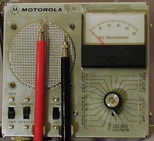
The TRN5080A test set was made for the MSR2000 series of stations, and has the
functionality of the TLN1857 shrunk down to a small box. The far end top has a meter
reversing switch at the top and the metering test point rotary switch on the bottom.
The near end has a speaker on/off switch at the top, and a cable that plugs into the
speaker backplane connector at the bottom. The main metering cable comes out of the
bottom.
The TRN5079 is a similar-styled half-length box that is the speaker only, but any 8
ohm speaker will work on the MSR once you add the correct connector. The backplane
has two male pins sticking up and the speaker cable has a small two-pin female
connector.
The TLN2418A Remote Metering Panel (RMP) and TLN2419A Diagnostic Metering Panel (DMP) were made for the MSF5000 / PURC5000 / MSF10000 station. Either also works with the PURC5000 Link Receiver and possibly other stuff.
The full kit includes the meter, flat 40-conductor cable, RJ45 8-conductor round
cable, red and black test probe leads, and the manual (not shown in this photo).
There's an amplified speaker (with on/off switch) in the left half, a standard 50uADC
meter (with input selector and polarity reversing switches) in the middle, a two-digit
LED channel number display (to the right of the meter), and address and data switches
and a matrix of digital signal display LEDs in the right half.
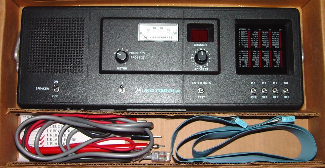
Photo courtesy of WA1MIK.
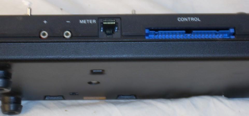
The test cables plug into the front edge.
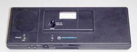
The TLN2418A Remote Metering Panel (RMP) is identical except it has blank panels
instead of the 2-digit display and the LED matrix display (it consists of just the
amplified speaker and meter, and their associated switches).
The TLN2418 / TLN2419 series has a semi-fatal design flaw, as this email to repeater-builder from Brian Alesio shows:
Nothing like a broken piece of test equipment. Going to a site for emergency repair and finding you've got a bad test set is worse than being bitten by your seeing eye dog. Just passing along an experience related to the TLN2418A and TLN2419A MSF5000 test sets. I have had a test set fail due to secondary damage from being knocked about. You may be able to save future aggravation by opening your test set and re-securing the speaker, which is held in place by push on spring clamps and some not so hefty plastic pins. In my case the speaker detached, slid over and contacted active electronics, which were not to happy for that experience. If yours is not broken, additional insulation on the back of your speaker would prevent this. If some pins are missing, some "Goop" or the like might be helpful to permanently hold the speaker in place.Bob Meister WA1MIK read the above and commented:
Besides those press-on clip studs breaking off and rattling around (the studs are not repairable unless you want to drill holes through the front panel and use #4-40 hardware, which isn't a bad idea), if you drop the test set, it will most likely fall against something on the way down and break one or more of the switch handles. The exact replacement switches are NLA from Motorola, but you may be lucky enough to find a suitable replacement elsewhere.I've seen one where the owner broke out the plastic pegs, drilled holes in the front panel, ran 4-40 screws through large diameter flat washers (so the screw heads would not pull through the plastic), then used 4 more washers to hold the speaker in place. Nylok nuts on the screws held everything together.
There's about 1.5GB of additional Motorola Test Set information, with some duplication, that was sent to repeater-builder anonymously on a DVD. It's stored at our sister-site that can be found here (Motorola Index #3).
By the way, the letters "TEK" decode as follows:
T echnical
E quipment
K it
Back to the top of the page
Up one level (Moto index)
Go to the Home page
Contact:
Mike Morris WA6ILQ can be reached at (callsign) at repeater-builder.com
Credits:
Tube-type base station metering kit schematic was scanned by Bob WA1MIK from the
1960s book titled "FM Schematic Digest - A Collection of Motorola Schematics,
Published by: Sherman M. Wolf - Boston, Massachusetts" - commonly called "The Red Book".
Mr. Wolf also publihed "The White Book" whhich was a similar book of GE schematics.
Other contributions from Eric Lemmon WB6FLY (SK), Skip Hansen WB6YMH, Jim Scott N8ORJ, Don Best N6ALD, Doug Marston WB6JCD (SK), Jeff Kincaid W6JK, Neil McKie WA6KLA (SK) and others.
This page was created on 04-Apr-2007.
Artistic layout, several of the photos and the hand-coded HTML is © Copyright 2007 and date of last update by Michael Morris WA6ILQ.
Motorola® is a registered trademark of Motorola Inc. Logo image used with permission.
Registered trademarks, service marks, or copyrights of Motorola Inc. include all of the the model names ("Deluxe Line", "Research Line", Motrac, Motran, MICOR, etc.) mentioned above, and a lot more that I can't remember at 2am as I'm creating this page. In short, trademarked / service-marked names belong to the owner and no misuse, violation or infringement is intended.
This web page, this web site, the information presented in and on its pages and in these modifications and conversions is © Copyrighted 1995 and (date of last update) by Kevin Custer W3KKC and multiple originating authors. All Rights Reserved, including that of paper and web publication elsewhere.