Back to Motorola index
Back to Home
Duplexer / Cavity Filter
Compiled and HTML'd by Mike Morris WA6ILQ

|
Back to Antenna Systems Back to Motorola index Back to Home |
The Motorola® T1500 Duplexer / Cavity Filter Compiled and HTML'd by Mike Morris WA6ILQ |
|
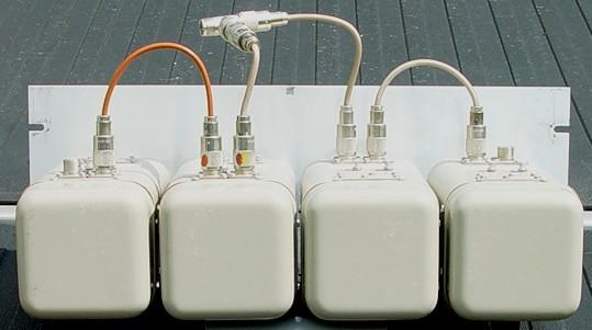
Photo 1: Rear view
Note that the left pair of cavities have the cables connected at the rear of the cavities,
and the right pair are at the front (which is defined as the end with the mounting panel,
and the tuning shaft or knob).
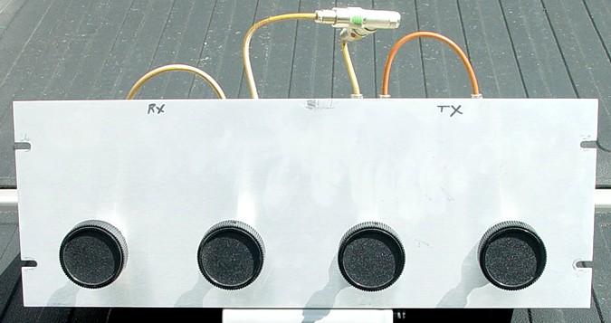
Photo 2: Front view
This photo is unusual in that the knobs are present, as opposed to 90% of the ones I've
seen in the field where they are missing. The absence of the knobs keeps the children from
messing up the careful tuning of the duplexer. Also note that the cavities are labeled
"transmit" and "receive". Well, ignore that labeling. You want to think in terms
of "high frequency side" and "low frequency side" since in some geographical areas the
transmitter is on the higher of the two frequencies and other areas the receiver is on the
high side... Regardless of which side of the frequency pair is receive or transmit,
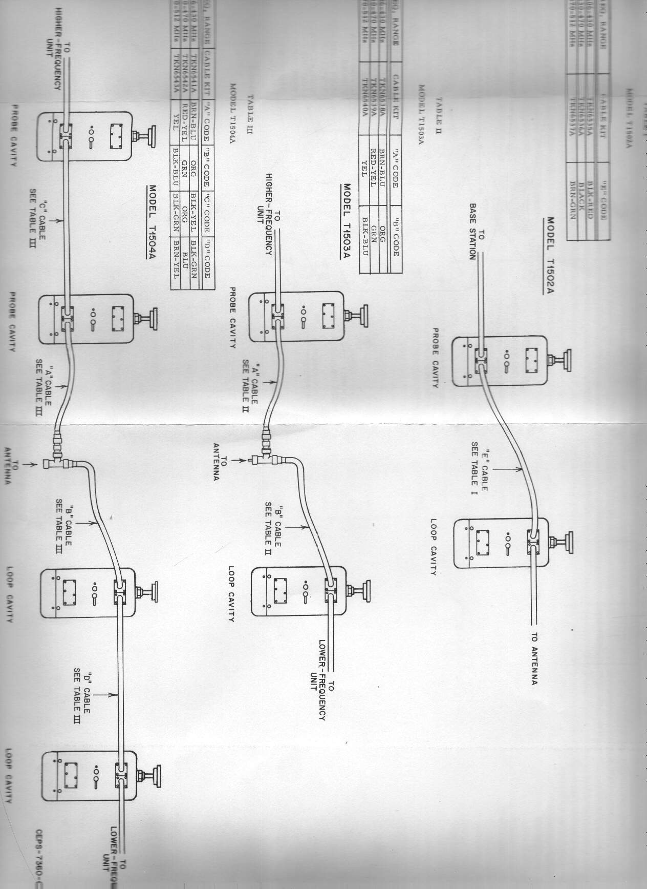
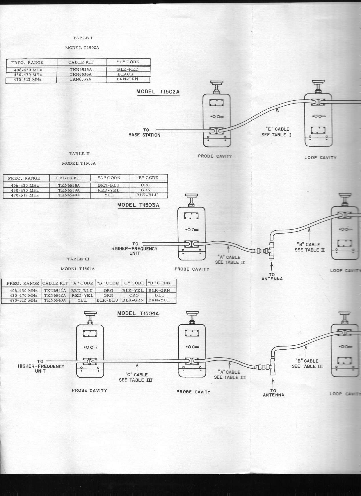
the lower of the two frequencies should connect to a loop cavity, which has the two connectors
close to the front of the cavity, and the higher of the two frequencies should connect to a
probe cavity, which has the two connectors close to the butt (rear) of the cavity. Also
be careful to use only silver plated double shielded cables and silver plated connectors
(especially NOT nickel or chrome plated).
The knobs are listed in the documentation as part number 36-84458A01 but they are now
No Longer Available (NLA). Anybody have aan alternate source of them?
(I wasn't able to find anything in the McMaster-Carr or Grainger industrial supply house catalogs)
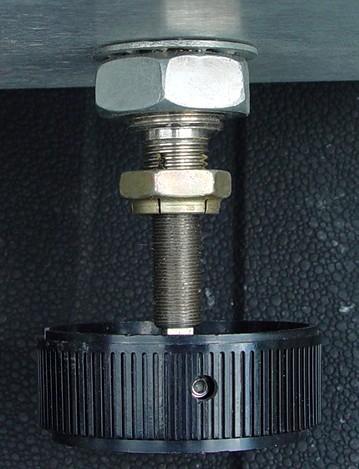
Photo 3: One cavity's adjustment shaft
In case yours are missing, Scott KBØNLY located the exact locknuts.
They can be purchased from McMaster-Carr as part
number 94830A550; they're $8.18 for a pack of 5 (price as of 2005).
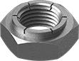
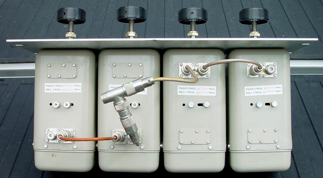
Photo 4: top view (click for full size image)
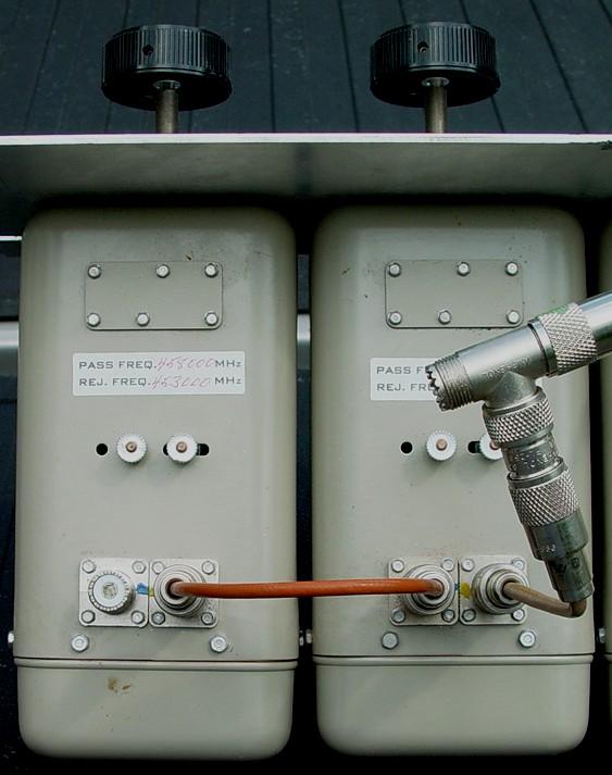
Photo 5: The high frequency side. Notice how the Tee connector is cabled?
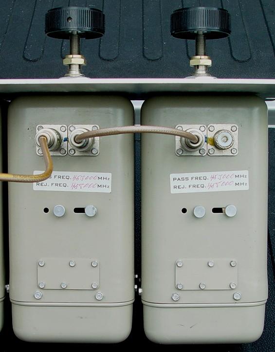
Photo 6: The low frequency side
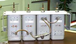
Photo 7: Another top view
The side panels visible in this photo are rare. They are made by Chatsworth
Products Inc. (http://www.chatsworth.com) and allow any rack mounted equipment to be offset
in a rack for easier mounting and adjustment. They are available in several different offsets.
Note how the center coax T-fitting is cabled in the above photo versus the other photos. This photo shows it miscabled, on purpose, just for this photo - while more physically symmetrical, the coax lengths are precisely measured to the 1/8 of an inch, and the cabling was specifically manufactured for the configuration shown in the upper photo! The performance will be severly degraded if it is used as shown in this picture.
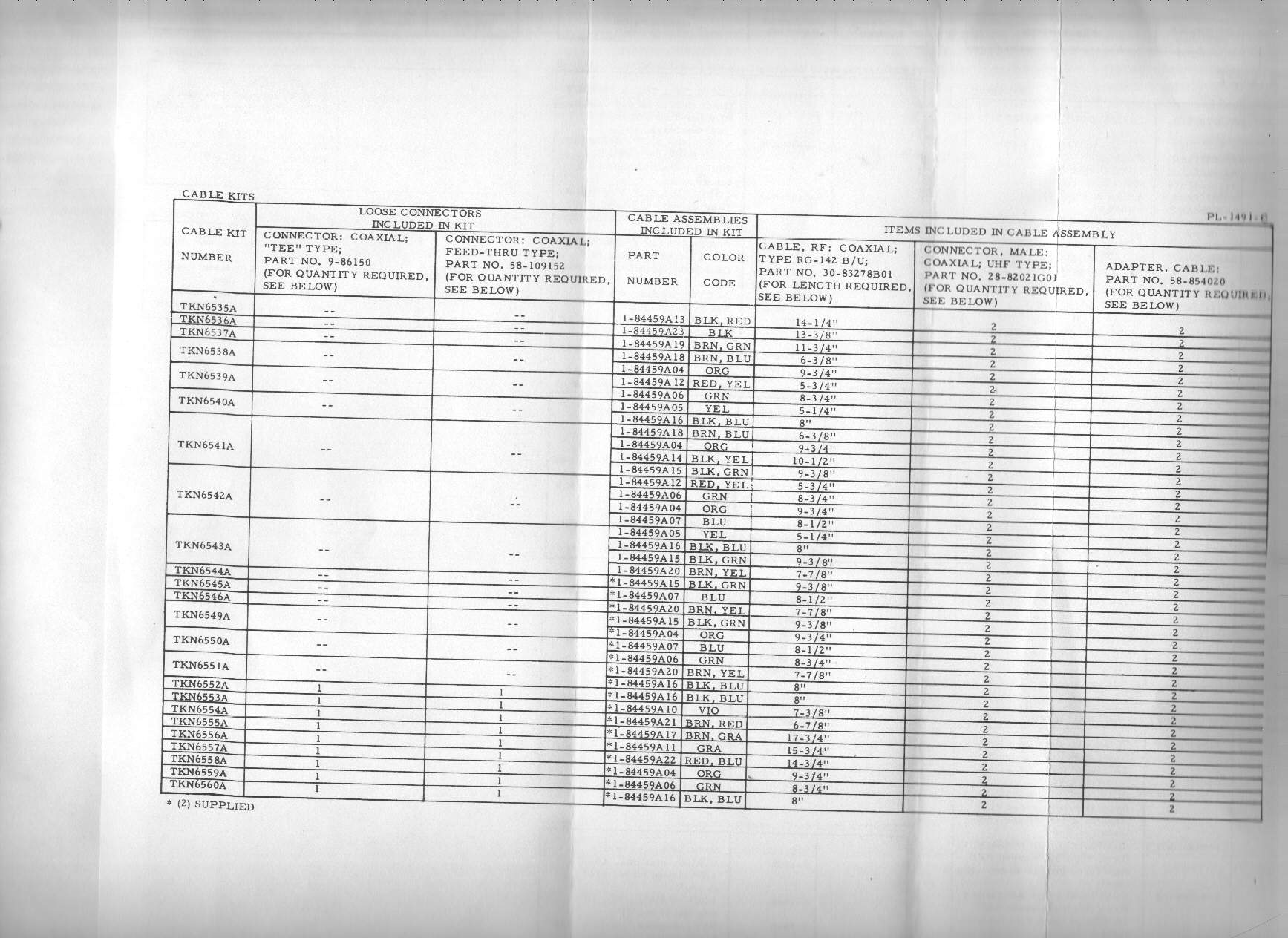
From the manuals below:
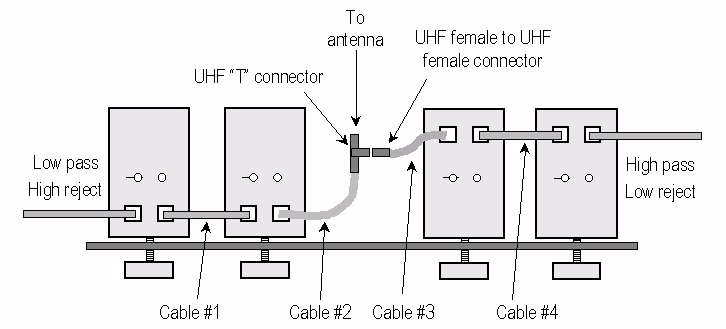
| Cable lengths in inches, from tip of PL259 to tip of PL259 | ||||
|---|---|---|---|---|
| Cable #1 | Cable #2 | Cable #3 | Cable #4 | |
| 406-430 MHz | 9-3/8 | 9-3/4 | 6-3/4 | 10-1/2 |
| 430-470 MHz | 8-1/2 | 8-3/4 | 5-3/4 | 9-3/4 |
Documentation:
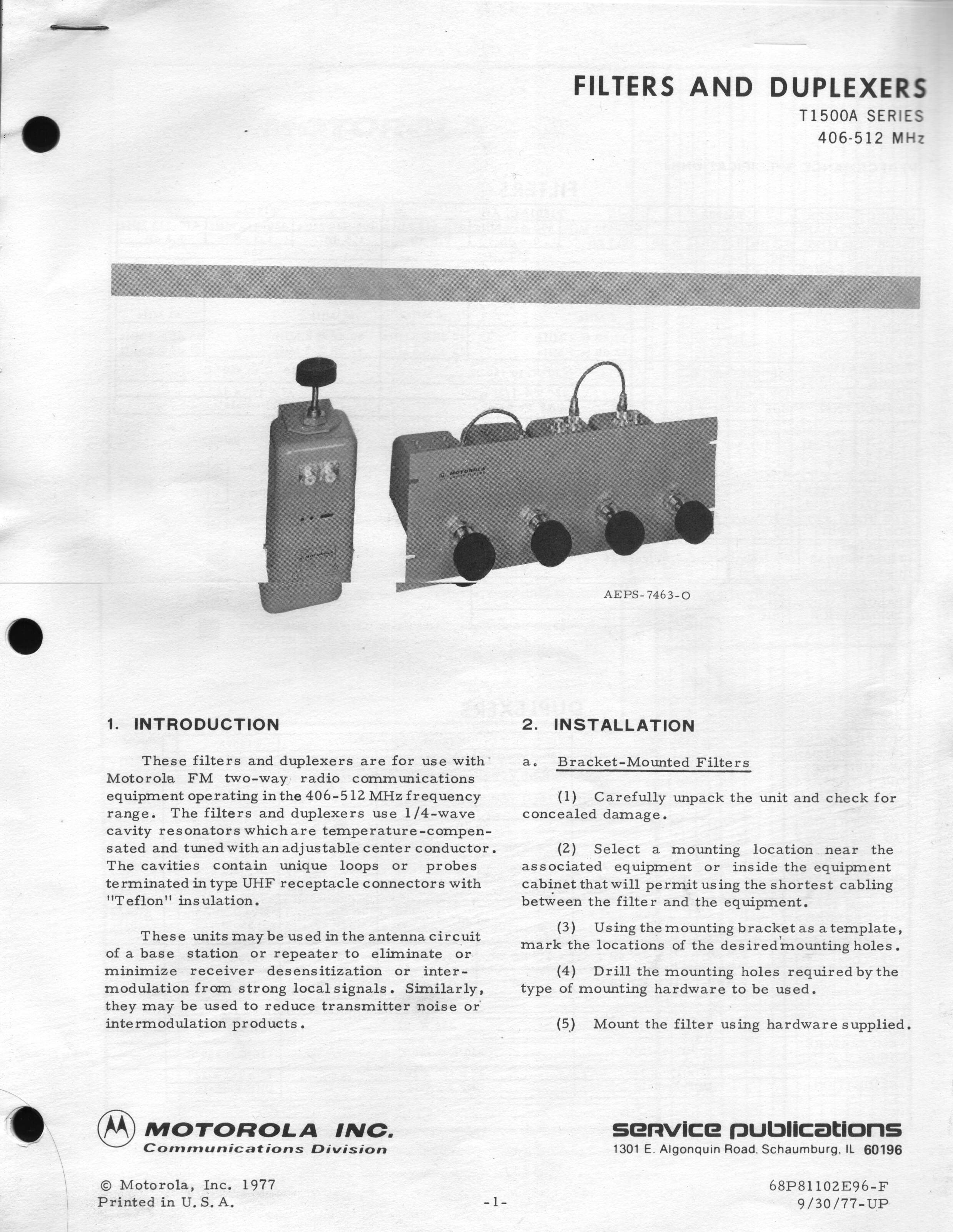
The original Motorola T1500 manual is part number 6881102E96, titled "Filters and
Duplexers, T1500A series, 406-512 MHz"
T1500 manual version "G" dated 01/25/1983 1.3
MB PDF file
This manual was scanned with a "full page" scanner, with the pullout pages scanned as
full width scans (no cutting and pasting, or "stitching" needed).
Motorola T1500 Cavity Aplication Notes, dated
22-July-1976 816 kB PDF donated by Bernie Dier KH6IAH by way of Bob
Hlivak NH6XO.
This is a complete walkthrough on combining using T1470 or T1500 cavities.
Below are scans of another version of the T1500 manual (version "F" dated 9-30-1977)
![]() Page 01 1.1 MB
Page 01 1.1 MB
![]() Page 02 261 kB
Page 02 261 kB
![]() Page 03 305 kB
Page 03 305 kB
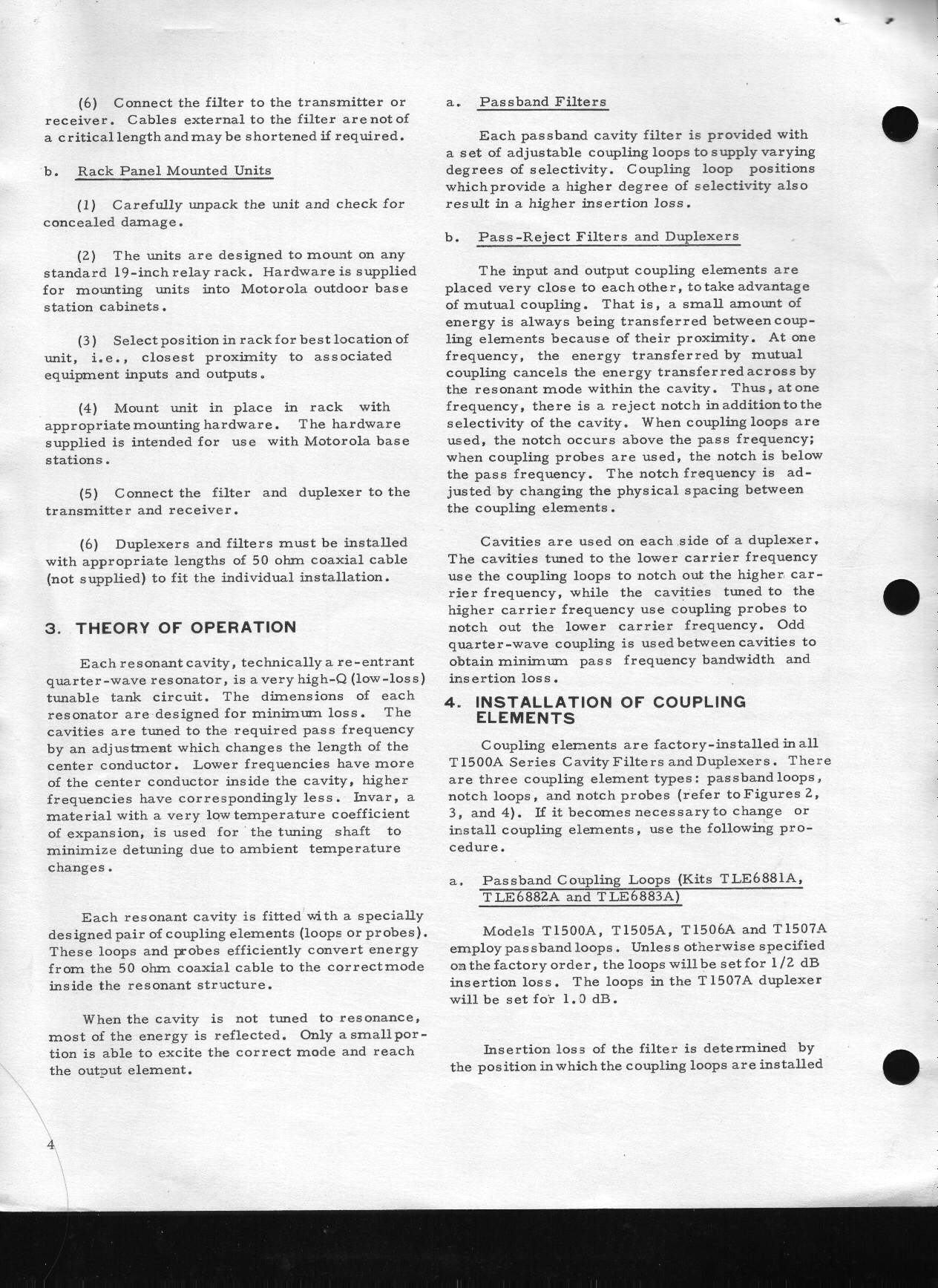
![]() Page 04 338 kB
Page 04 338 kB
![]() Pull-out
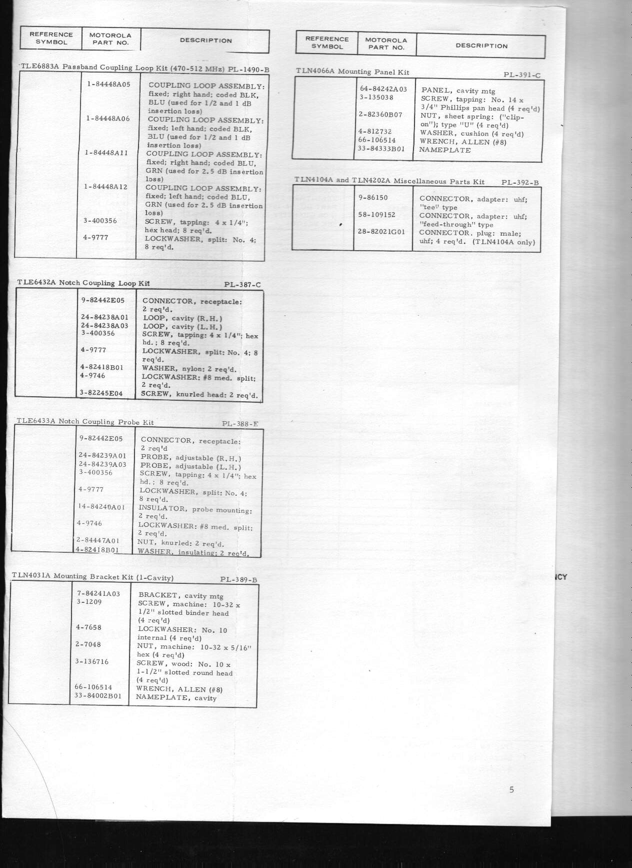
Parts List Page 05
Left 207 kB
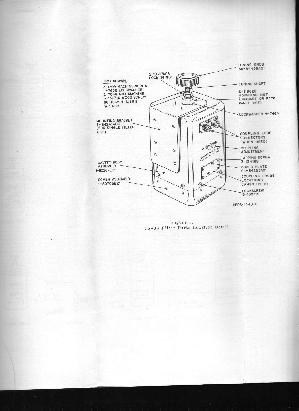
Page 05 Middle (physical
drawing) 153 kB
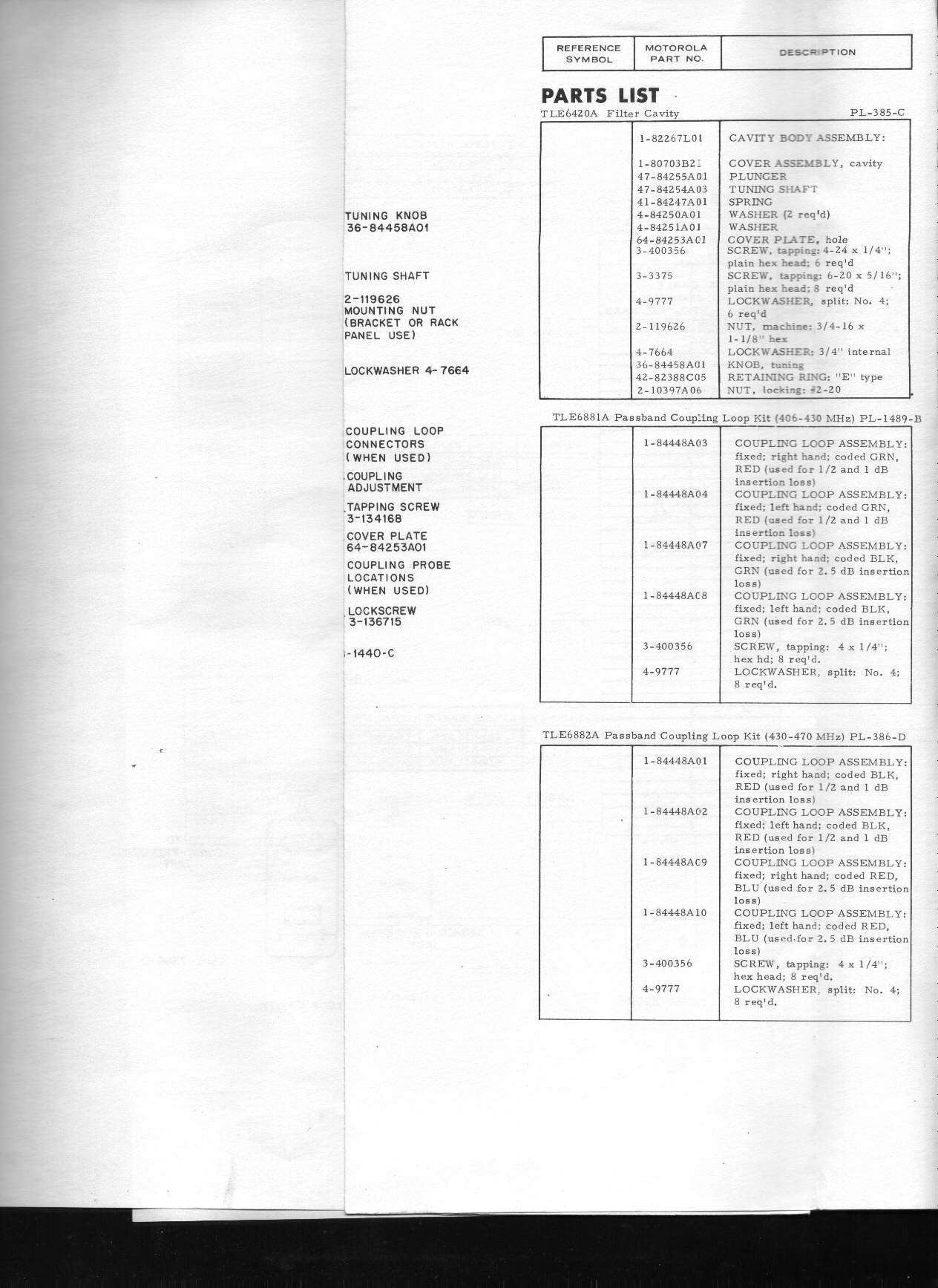
Page 05 Right 196 kB
Pull-out
Parts List Page 05
Left 207 kB
Page 05 Middle (physical
drawing) 153 kB
Page 05 Right 196 kB
![]() Pull-out
Inter-cavity cabling drawing Page
06 Left 162 kB
Page 06 Middle 197 kB
Page 06 Right 252 kB
Pull-out
Inter-cavity cabling drawing Page
06 Left 162 kB
Page 06 Middle 197 kB
Page 06 Right 252 kB
![]() Page 07 216 kB
Page 07 216 kB
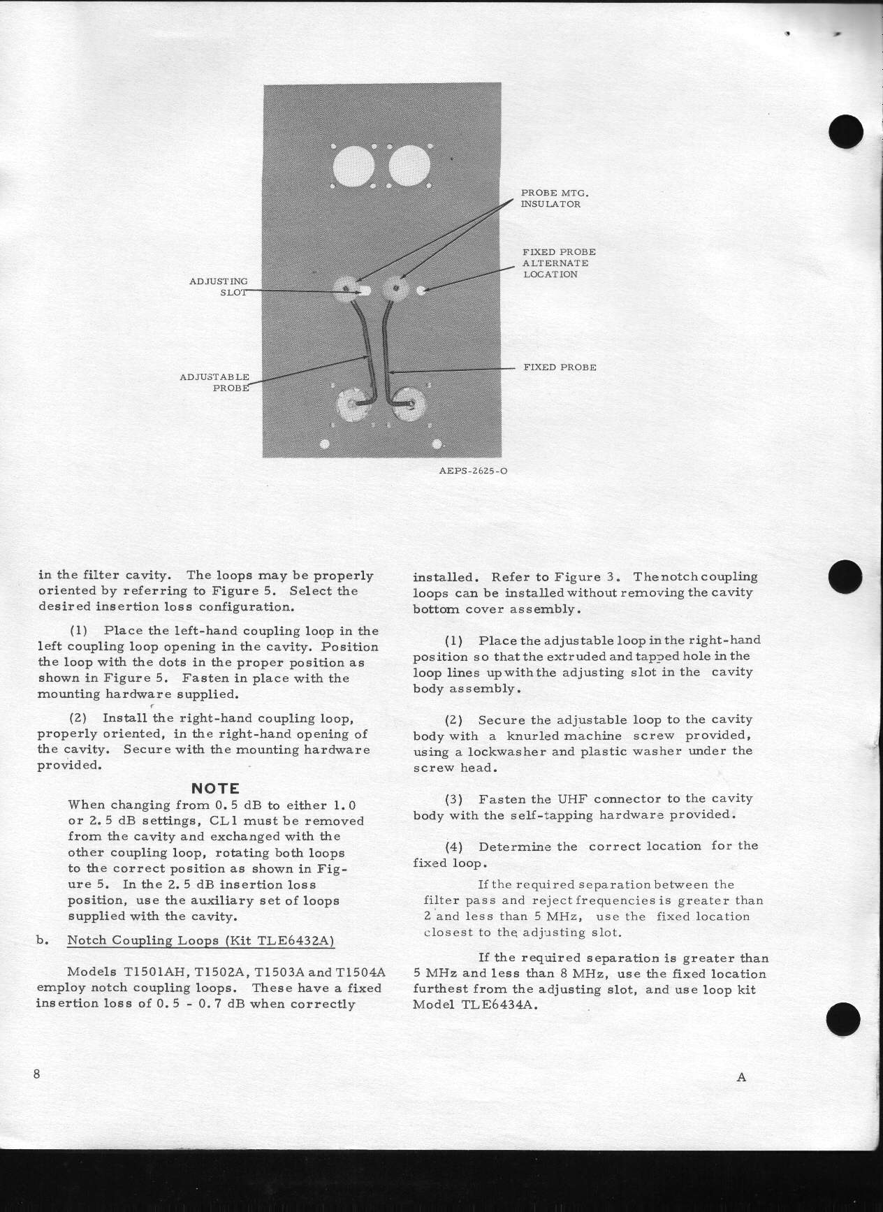
![]() Page 08 280 kB
Page 08 280 kB
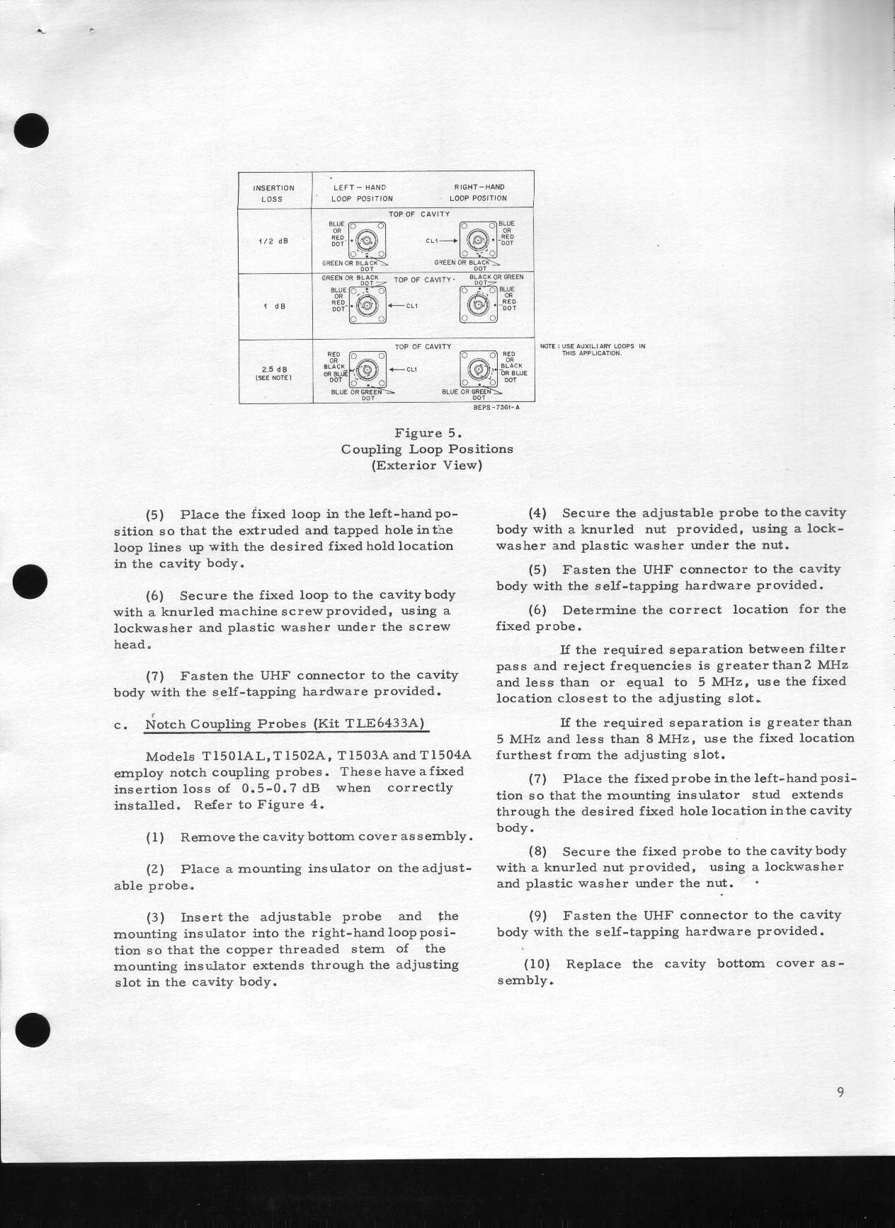
![]() Page 09 248 kB
Page 09 248 kB
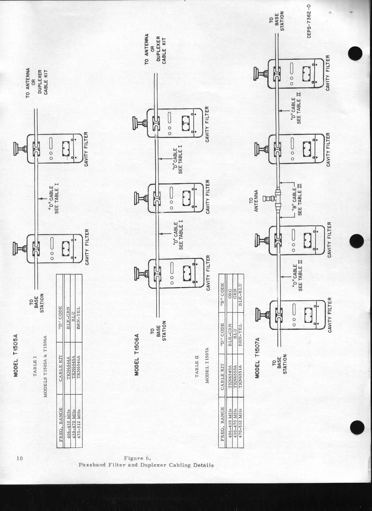
![]() Page 10 224 kB
Page 10 224 kB
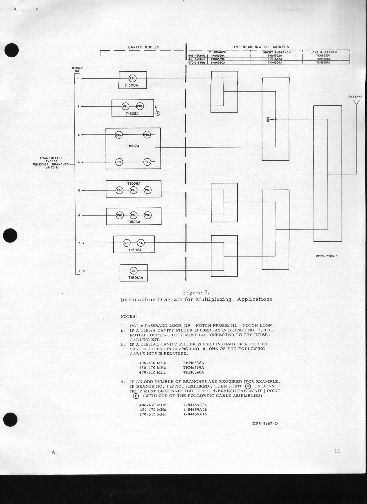
![]() Page 11 206 kB
Page 11 206 kB
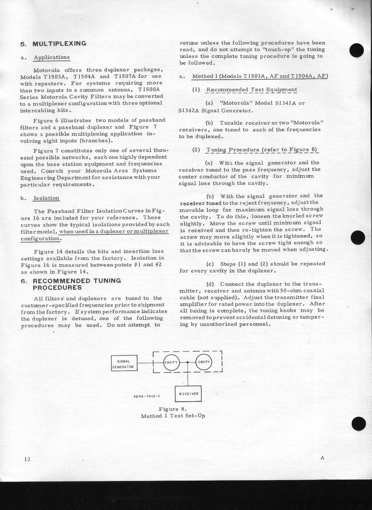
![]() Page 12 289 kB
Page 12 289 kB
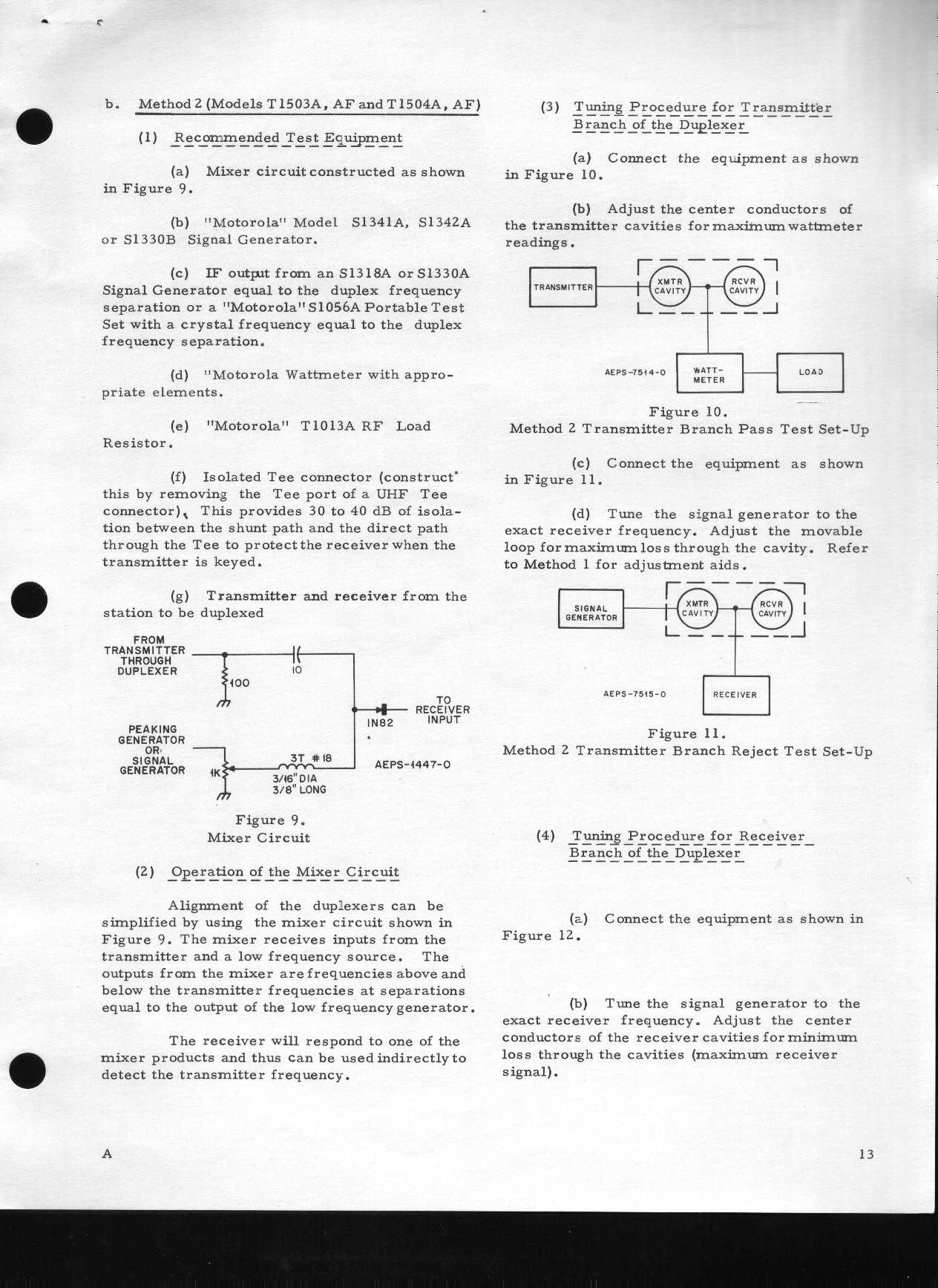
![]() Page 13 261 kB
Page 13 261 kB
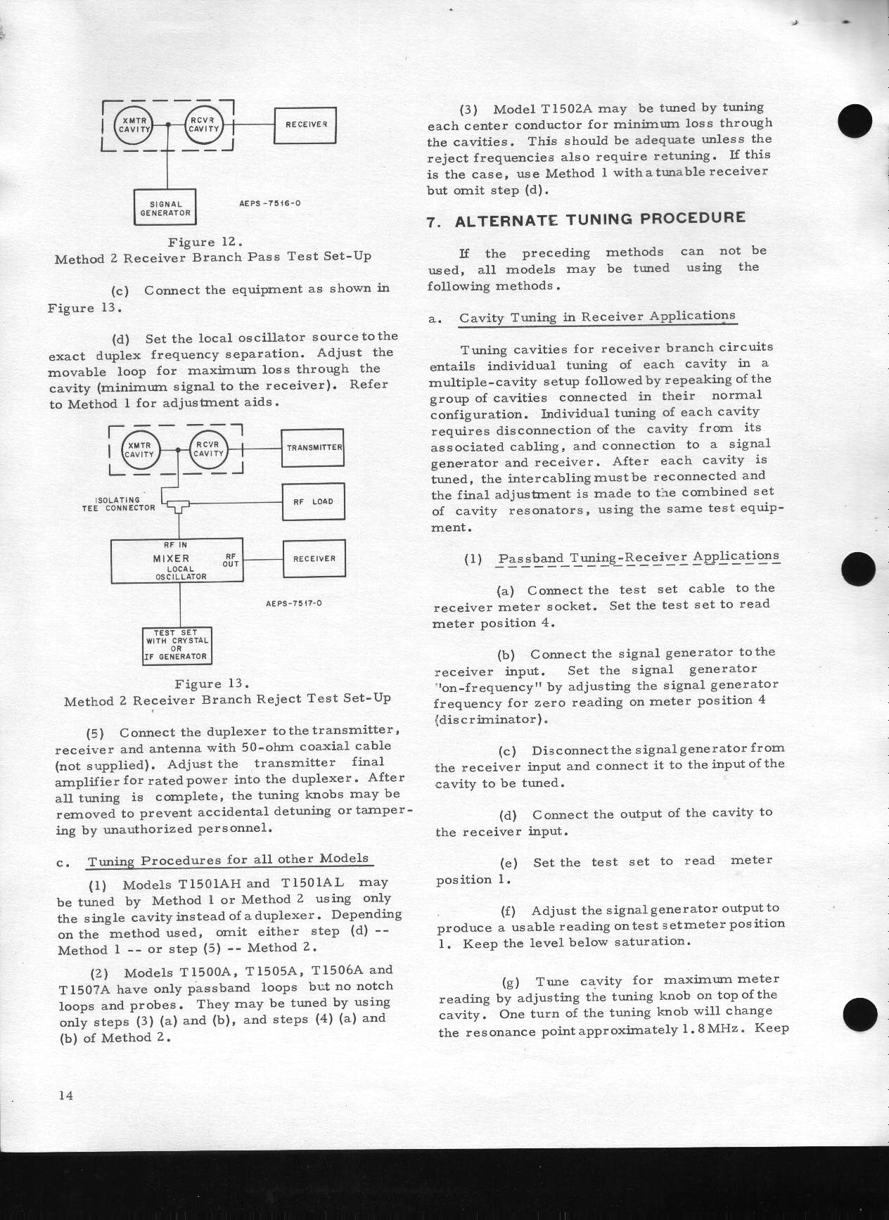
![]() Page 14 299 kB
Page 14 299 kB
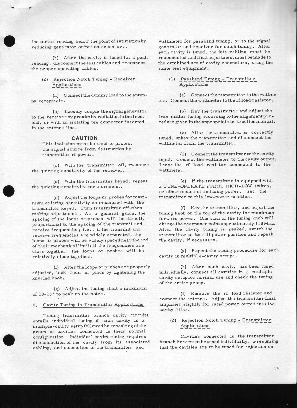
![]() Page 15 324 kB
Page 15 324 kB
![]() Page 16 206 kB
Page 16 206 kB
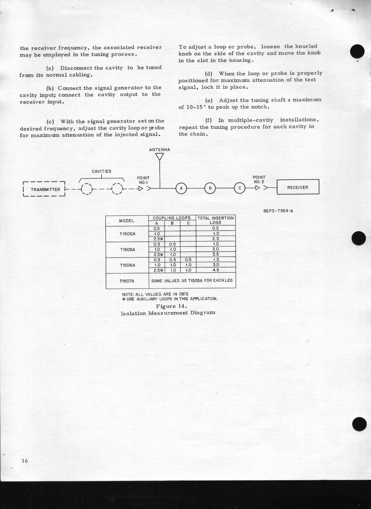
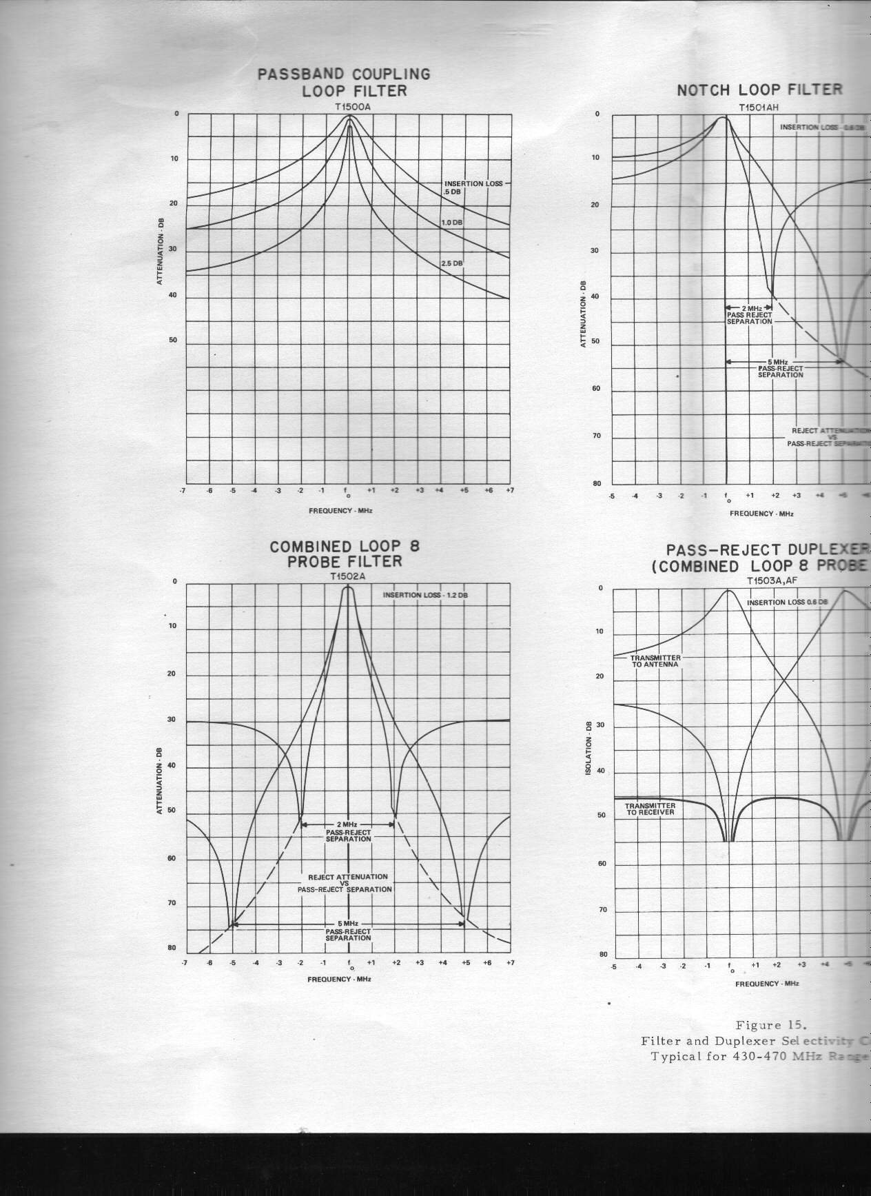
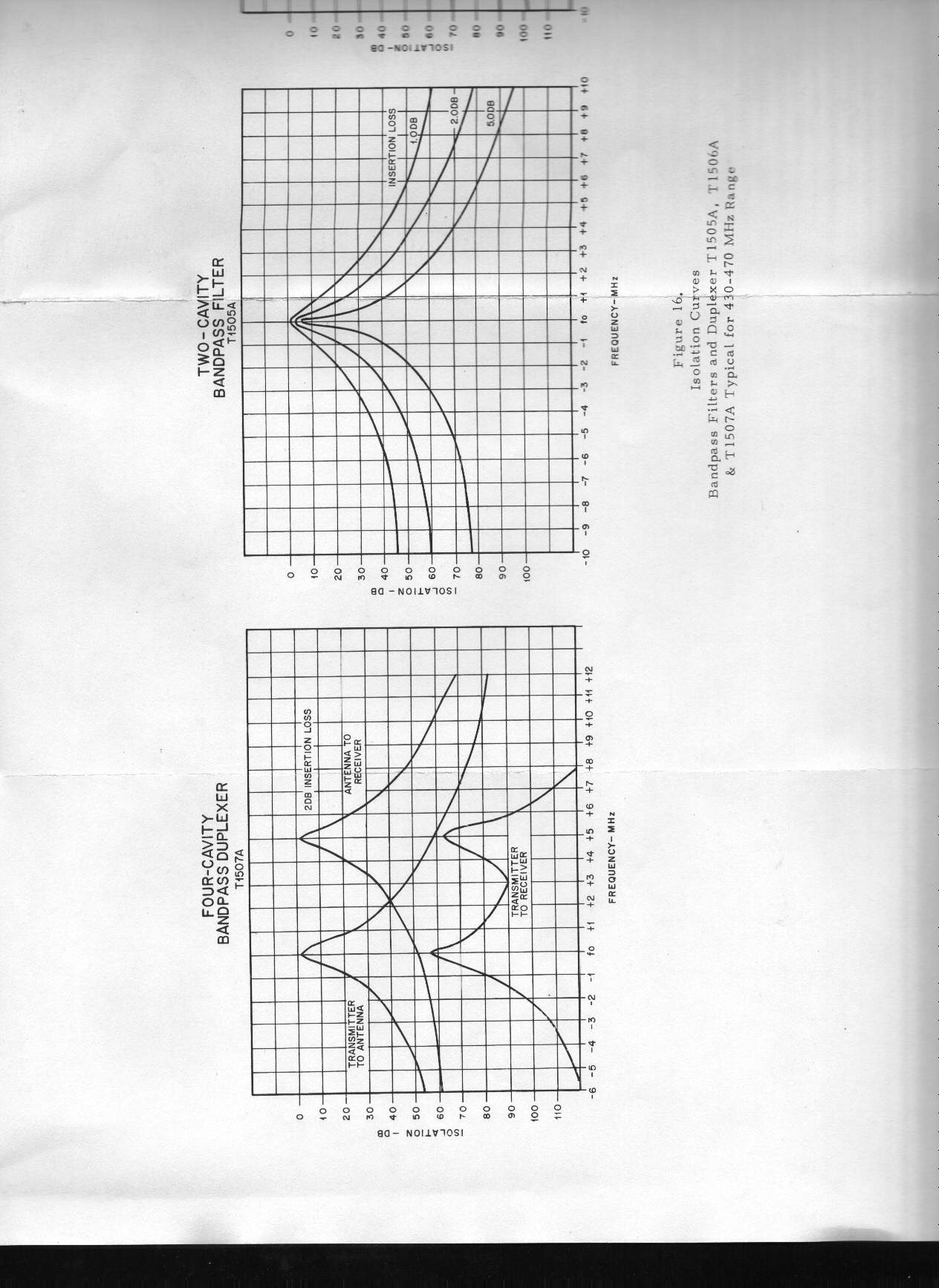
![]() Pull-out
Performance graphs (first page of graphs)
Page 17 Left 239 kB
Page 17 Right 245 kB
Pull-out
Performance graphs (first page of graphs)
Page 17 Left 239 kB
Page 17 Right 245 kB
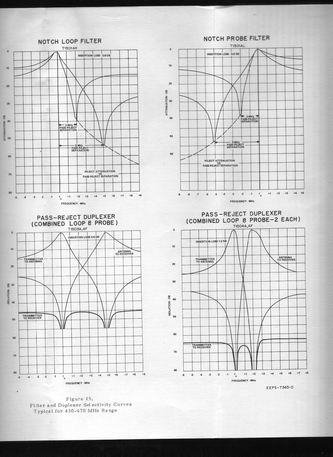
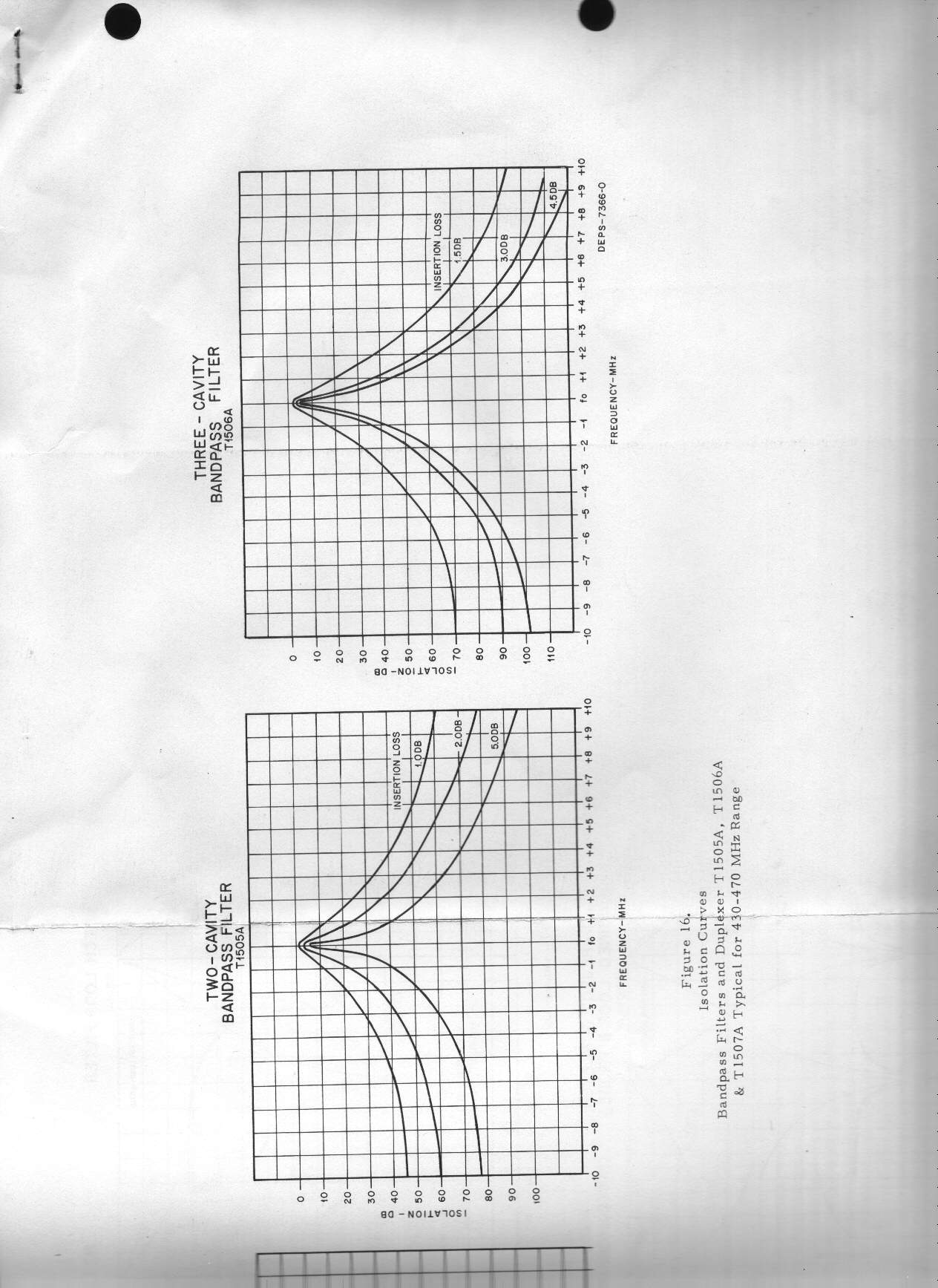
![]() Pull-out
Performance graphs (second page of graphs)
Page 18 Left 199 kB
Page 18 Right 195 kB
Pull-out
Performance graphs (second page of graphs)
Page 18 Left 199 kB
Page 18 Right 195 kB
A single 2.4 MB PDF file of a version "E" writeup dated 4/7/1976.
The Cactus Radio group has published a tech note on refurbishing the T1500 cavities.
From their web site at
http://www.cactus-intertie.org/:
This Technical Application Note describes the process for disassembling, cleaning and reassembling the Motorola T1500 Series Cavities. http://www.cactus-intertie.org/LA/tec_not6.pdf dated June 26, 1999. A local copy can be found here.
Contact Information:
The author can be contacted at: his-callsign // at // repeater-builder // dot // com.
Back to the top of the page
Back to the Antenna Systems index
Back to the Motorola main index
Back to Home
Scans of the over-20-year-old, version "F", no-longer-available-data sheet, date unknown
Photos 1-6 by Bob Meister WA1MIK.
Photo 7 by Chuck Krinke WA6LWB made at the authors request just to show the miscabling.
Motorola® is a registered trademark of Motorola Inc.
This web page created by Mike Morris WA6ILQ in August 2004.
This web page, this web site, the information presented in and on its pages and in these modifications and conversions is © Copyrighted 1995 and (date of last update) by Kevin Custer W3KKC and multiple originating authors. All Rights Reserved, including that of paper and web publication elsewhere.