Up two levels
Back to Home
Syntor X9000 PA Low-Pass Filter
for Improved TX Operation
on 6 meters
By John Haserick W1GPO
With Help From Robert Meister WA1MIK

|
Up one level Up two levels Back to Home |
Effects of Retuning the Syntor X9000 PA Low-Pass Filter for Improved TX Operation on 6 meters By John Haserick W1GPO With Help From Robert Meister WA1MIK |
|
Background:
In my previous article, I modified the coil spacing in the transmitter's low-pass filter to improve efficiency of the power amplifier. At the time, this seemed to be worth the effort as this filter had a fairly sharp roll off just above 54 MHz.
Most of the following was extracted from the low-band Syntor X9000 manual:
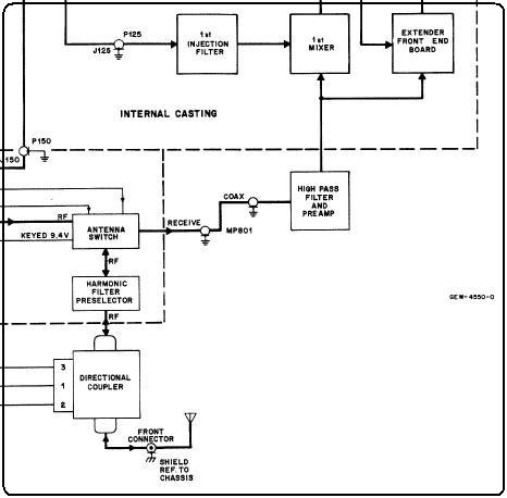
The low-band pre-selector consists of two filters separated by the antenna switch (on the PA). The receive signal goes first to a low-pass filter with a cutoff frequency of about 54 MHz. (This filter also serves as the transmitter harmonic filter.) If the radio is in the receive mode, the antenna switch passes the receive signal and applies it to the high-pass portion of the pre-selector, a seventh-order elliptical filter with a cutoff frequency of about 28 MHz. The signal then goes to a standard NPN BJT preamplifier and then through a three coil low-pass filter consisting of L103 on the pre amp board and L150 and L151 on the mixer board, before being presented to the first mixer.
This means the low-pass filter in the PA sets the high end for the receiver band-pass.
The block diagram snippet below leaves out the second low pass filter, but otherwise shows the major assemblies involved in the receive signal path.
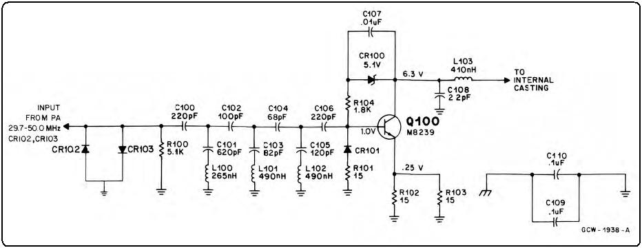
The preamp's input filter and the first section of the 2nd low pass filter are shown in the snippet below.
The following trace, measured between the input of the pre-amp (PA disconnected) to a 10K resistor off the junction of R151 and R152 at the input of the mixer, shows the frequency response of the receiver filters. Click on any spectrum photo for a larger image.

Measuring Sweep with All Filters Combined:
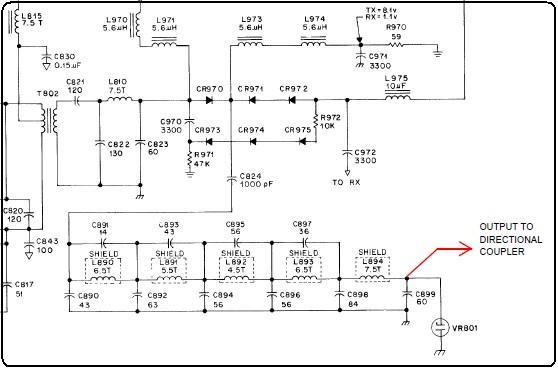
The pre-amp was reconnected to the PA and measurements were made from the radio antenna connector to input of 1st mixer. Here's a schematic of the low-pass filter showing the receiver connection point at C972.
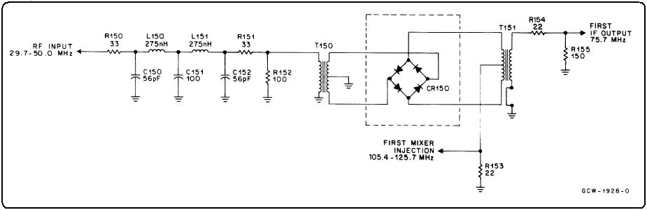
Here's a schematic of the mixer circuit.
I then took sweeps from the radios antenna jack to mixer showing the combined result of all three filters on two radios: one with an unmodified PA harmonic filter, and the other modified as previously written. The conclusion is that spreading the harmonic filter coils just enhances transmitter efficiency above 52 MHz, does little for reception, and in fact might degrade reception if there are nearby TV channel 2 or 3 transmitters.
See the unmodified radio antenna jack to mixer trace below.

For comparison, here's the sweep of the entire radio from the antenna jack through the PA's modified low-pass filter through the receiver's filters and ending at the mixer.

Further Testing:
At Bob's suggestion, additional measurements were performed with stock and modified radios under identical test conditions.
The photo below is the response of the harmonic filter in modified radio #1.

The photo below is the response of the harmonic filter in modified radio #2.

The photo below shows a radio without the harmonic filter coils spread, in other words, a stock radio.

The first two traces look amazingly similar, as they should, with both having just a few dB attenuation at 59 MHz (one division) and over 30dB attenuation at 64 MHz. The last, being the unmodified radio, has over 20dB attenuation at 59 MHz (one division) and over 40dB attenuation at 64 MHz. Some of this attenuation is due to the 10K resistor between the mixer and the analyzer input. So in this case, the unmodified harmonic/low-pass filter gives better rejection of TV channels 2 and 3 into the receiver or coming out of the PA.
The photo below shows all of the filters at work as it covers 0-100 MHz. The ripple below 30 MHz is due to the multiple sections that make up the front-end filter. This is on an unmodified radio.

The photo below shows the response of just 25-75 MHz. This is the same unmodified radio.

In all cases the radios were powered up, the sweep generator was fed to the drawer antenna connector, and the SA got its signal from the mixer input thru a 10K resistor.
Credits and Acknowledgements:
Schematic snippets came from the Motorola Syntor X9000 low-band service manual, 6880101W95-D.
Thanks go to Bob WA1MIK for persisting in getting all the connections and traces to make sense.
Contact Information:
The author can be contacted at: jhaserick84 [ at ] comcast [ dot ] net.
Back to the top of the page
Up one level
Up two levels
Back to Home
This article originally written 17-Jan-2021.
This web page, this web site, the information presented in and on its pages and in these modifications and conversions is © Copyrighted 1995 and (date of last update) by Kevin Custer W3KKC and multiple originating authors. All Rights Reserved, including that of paper and web publication elsewhere.