Up two levels (Moto index)
Back to Home
Station Information
By Robert W. Meister WA1MIK

|
Up one level (Spectra index) Up two levels (Moto index) Back to Home |
Motorola Spectra Desktop Station Information By Robert W. Meister WA1MIK |
|
Overview:
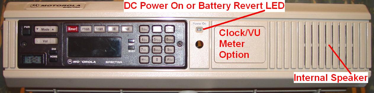
These self-contained stations come in various configurations. Inside you'll find a Spectra remote-mount mobile radio, 13.8VDC 10A power supply that's switch selectable for 120/240VAC at 47-63 Hz, remote control interface board, and a continuously running fan that blows air into the cabinet from the rear directly onto the radio's heat sink. There are provisions for a foam filter to be installed on the fan, but none was present on my station; I have since added one. Louvers on the sides of the cover let the warm air out. There is no AC or DC power switch on the station; plug it in and it starts running. A battery revert option is available. The power button on the Spectra control head only turns the radio on and off. Interfacing to remote control equipment is via two DB25F connectors on the rear panel. If the station has a control head mounted to the front panel, local operation is also possible. Without a control head, the station may only be accessed through a remote control console. Here's the front of my L37KGM5174AM station:
The station cabinet is designed for ease of maintenance. Major assemblies snap into place and small screws are used to hold some units for shipping. Minimal tools are required.
The top cover is a snug fit. Two cabinet latches on the rear panel are lifted up to engage the rear edge of the cover, then pressed down to pry the front cover backwards to release it. These are easily broken on older stations. The cover is the only thing that holds the front panel into the chassis; be careful when lifting the unit with the cover removed, as the front panel will easily slide up and out of the chassis.
Station programming is accomplished using the regular Spectra Radio Service Software RVN4000 and RVN4001. The RIB cable plugs into the 15-pin accessory jack on the rear of the radio chassis inside the station. All of the programming signals exist on Accessory Jack J3 so it should be possible to make a special RIB cable that would allow programming without removing the top. The model and serial numbers read out of the radio matched those on the station's label. My particular radio has Version 6.15 firmware in it (this is one of the latest versions).
The Spectra radio can support all standard Spectra options except the Direct Entry Keyboard, although I can't think of a reason to connect a siren to the station!
The empty hole below the Power LED probably should have a removable plug installed, however in other stations it could hold a secure key loader jack or other option. The manual shows nothing for this location.
When an ASTRO Spectra radio is installed, the station is called a Consolette.
A similar desktop station with one or two MaxTrac radios installed is a DeskTrac.
The following data was extracted from the manual:
| Band and Power Level |
Max. AC Current | Maximum DC Current | |||
|---|---|---|---|---|---|
| Stdby | Xmit | Stdby | Rcve | Xmit | |
| VHF 25 watts | 0.82 A | 1.51 A | 1.5 A | 3.5 A | 8.5 A |
| VHF 50 watts | 0.82 A | 2.46 A | 1.5 A | 3.5 A | 14 A |
| UHF 20 watts | 0.82 A | 1.42 A | 1.5 A | 3.5 A | 8 A |
| UHF 40 watts | 0.82 A | 2.39 A | 1.5 A | 3.5 A | 13.5 A |
| 800 MHz 15 watts | 0.82 A | 1.24 A | 1.5 A | 3.5 A | 7 A |
| 900 MHz 4 watts | 0.82 A | 0.89 A | 1.5 A | 3.5 A | 6.5 A |
| 900 MHz 12 watts | 0.82 A | 1.42 A | 1.5 A | 3.5 A | 8 A |
My 900 MHz 12 watt 120VAC station measured 0.35 amps in standby and 1.2 amps when transmitting.
Spectra Radio Interconnection and Configuration:
A standard Spectra control head is mounted to the front panel of the station; the station in the photo above has an A7 head. (The manual does not say anything about the type of control head and only shows a photo of one with an A7. The control head would be omitted on a digital remote-controlled station.) A small circuit board plugs into the 30-pin control head connector on the back and has flat cable soldered to it. The other end has a 34-pin flat connector which plugs into the audio interface board underneath the radio.
A 50-pin flat cable plugs into the audio interface board and is terminated in two DB25M connectors that plug into two jacks on the front of the radio chassis.
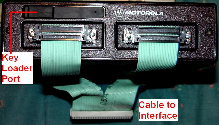
The low- or mid-power radio chassis has a front panel (HLN6261A interconnect board) with two DB25F connectors and a rubber-covered 6-pin microphone connector. This panel plugs into the 38-pin command board socket located inside the front of the chassis. The 6-pin connector is used for loading SecureNet encryption keys. This same panel would be used on a remote- or trunk-mount radio. Here's the front of the radio:
The radio uses the standard two-pin polarized DC power connector. The 15-pin accessory jack on the back of the radio is utilized primarily for programming and is otherwise unoccupied.
A standard mini-UHF female connector is connected with a short piece of RG142 coaxial cable to a female N connector on the back of the station.
Here's the inside of the station with the front panel at the top:
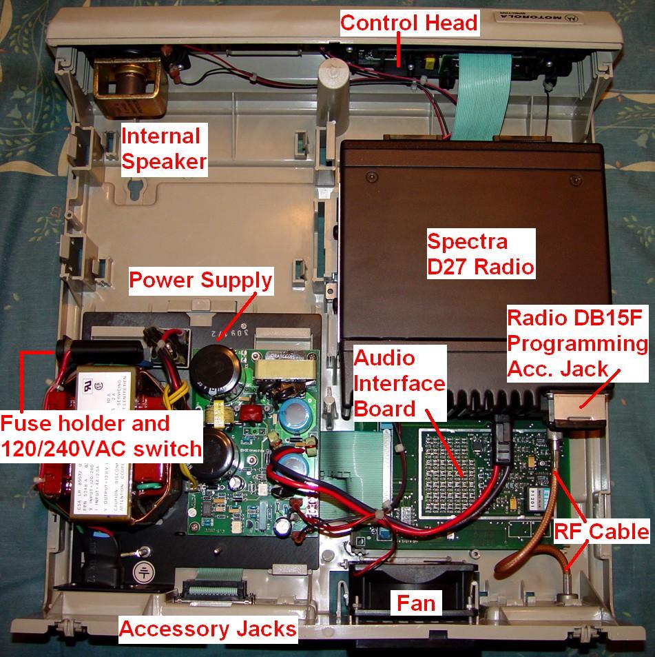
The additional space next to the Spectra radio could be used for other options, or for a second radio in a DeskTrac station. There's insufficient room here for a second complete Spectra radio. The black plate under the power supply is a heat sink.
Station Models:
There are only 10 model numbers for desktop stations equipped with regular Spectra radios, summarized below:
| Spectra Desktop Models | |||
|---|---|---|---|
| Model Number | Power | Band | Modes |
| L53KXM7174AM | 50 W | VHF | Conv. |
| L53ZXM5174AM | 50 W | VHF | Trunk. |
| L44KXM7174AM | 40 W | UHF | Conv. |
| L44ZXM5174AM | 40 W | UHF | Trunk. |
| L35KXM7174AM | 15 W | 800 | Conv. |
| L35ZXM5174AM | 15 W | 800 | Trunk. |
| L27KMM7170AM | 4 W | 900 | Conv. |
| L27KGM5170AM | 4 W | 900 | Trunk. |
| L37KMM7174AM | 12 W | 900 | Conv. |
| L37KGM5174AM | 12 W | 900 | Trunk. |
There is some non-standard-ness in the model numbers for the 900 MHz stations. A model of X37 would indicate a 30w Spectra radio, while X27 would be used for a 12w radio and X17 would represent a 4w unit. Regular Spectra radios are identified in this manner. Inside the L37KGM station is a D27 radio. The other model numbers appear to utilize the existing/correct numbering scheme.
The 14 ASTRO Spectra-equipped Consolette station model numbers are shown below:
| ASTRO Spectra Desktop Consolette Models | |||
|---|---|---|---|
| Model Number | Power | Band [1] | Control [2] |
| L04JKH9PW9AN | 25-50 W | VHF-R1 | REMOTE |
| L04KKH9PW9AN | 25-50 W | VHF-R2 | REMOTE |
| L04QKH9PW9AN | 20-40 W | UHF-R1 | REMOTE |
| L04RHH9PW9AN | 10-25 W | UHF-R2 | REMOTE |
| L04RKH9PW9AN | 20-40 W | UHF-R3 | REMOTE |
| L04SKH9PW9AN | 20-40 W | UHF-R4 | REMOTE |
| L04UJH9PW9AN | 35 W | 806-870 | REMOTE |
| L04JKH9PW7AN | 25-50 W | VHF-R1 | LOCAL |
| L04KKH9PW7AN | 25-50 W | VHF-R2 | LOCAL |
| L04QKH9PW7AN | 20-40 W | UHF-R1 | LOCAL |
| L04RHH9PW7AN | 10-25 W | UHF-R2 | LOCAL |
| L04RKH9PW7AN | 20-40 W | UHF-R3 | LOCAL |
| L04SKH9PW7AN | 20-40 W | UHF-R4 | LOCAL |
| L04UJH9PW7AN | 35 W | 806-870 | LOCAL |
Station Options:
There are multiple options; some are mutually exclusive or incompatible with others. (An even longer list, not shown, covers the ASTRO models.) The list is shown below:
| Spectra Desktop Options | ||
|---|---|---|
| Option | Description | Incompatible With L... |
| L28 | Battery Revert | 32 |
| L32 | 12V DC Only | 28 |
| L73 | Omit Microphone | 791 |
| L75 | Omit Time-Out Timer | |
| L114 | Clock/VU Meter | 791 |
| L146 | Tone Remote Control | 791 |
| L388 | DES Encrypt/Decrypt | 793,794,795,796,797 |
| L416 | PTT ID | 73,114,146 |
| L444 | Omit Conventional | 992 |
| L791 | Digital Remote Control | 73,114,146 |
| L793 | DVI-XL Encrypt/Decrypt | 388,794,795,796,797 |
| L794 | DVP Encrypt/Decrypt | 388,793,795,796,797 |
| L795 | DES-XL Encrypt/Decrypt | 388,793,794,796,797 |
| L796 | Fascinator | 146,388,793,794,796,797 |
| L797 | DVP-XL Encrypt/Decrypt | 388,793,796,795,796 |
| L798 | Physical Security | |
| L968 | OTAR/Multikey | 388,793,795,796,968 |
| L969 | Multikey Encrypt/Decrypt | 388,793,795,796,968 |
| L992 | Omit Plant Programming | 444 |
Audio Interface / Tone Remote Control Board:
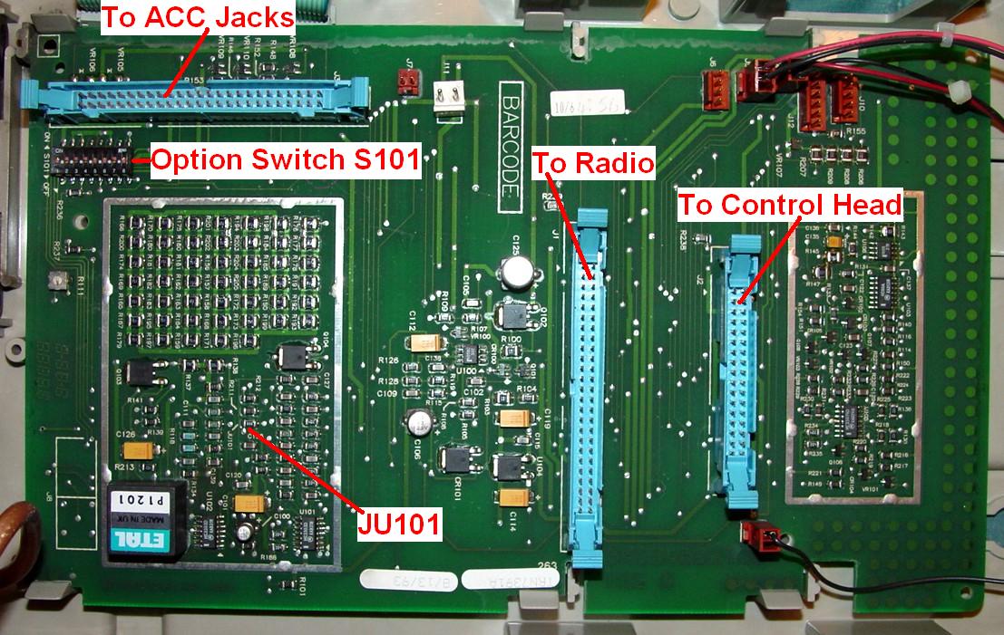
This board sits under the Spectra radio and serves as the primary interface between the radio chassis, control head, loudspeaker, and remote control equipment. Transmit and receive audio connections are present on the ACC 2 jack on the rear panel (the lower of the two DB25F connectors). You will also find PTT, MONITOR, and MRTI_AUD_CTRL lines here. The standard audio interface board supports extended local control. Here's a photo of this board with several connectors removed. The large array of 47 resistors near S101 is a 10w 16 ohm dummy load for the radio in configurations where no speaker is attached, i.e. when a digital remote control system is in use.
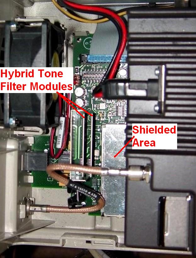
This board can be replaced with a Tone Remote Control board (Option L146) that responds to the standard High-Level Guard Tone, Function Tone, Low-Level Guard Tone sequence used by other Motorola equipment. The Function tones allow for selection of up to 8 modes. The tone functions are not programmable. A tone remote control unit or console could be configured to work with this station. The tone remote board has a shielded enclosure containing several large ICs (the microprocessor, EPROM, etc.), a crystal, several tone filter hybrids, and two transformers instead of the large exposed array of resistors shown in the photo above. See the photo below that shows a small part of the tone remote board.
The standard audio control board (TRN7391), and probably the tone remote control board (TLN3207), contains the same style electrolytic capacitors found in Spectra mobile radios that are known to leak and cause problems. If you find evidence that the radio or the control boards are more than 10 years old, replace the caps before they do damage. Read the Time Bomb Capacitors article in the Spectra section of this web site. My Spectra radio makes very loud popping sounds in the loudspeaker, a sure indication that the capacitors are bad. I'll be changing all of them.
The audio interface boards contain an 8-position DIP-switch (S101) and one soldered jumper (JU101) for configuring various options. These are detailed below. Bold green text is used to show the default condition.
| Spectra Desktop Interface Board Configuration Settings | |||
|---|---|---|---|
| Pos # | State | Audio Interface | Tone Remote Control |
| 1 [1] | ON | Spectra control head power button disabled. | Spectra control head power button disabled. |
| OFF | Spectra control head power button enabled. | Spectra control head power button enabled. | |
| 2 [2] | ON | Battery revert option not present. | Battery revert option not present. |
| OFF | Battery revert option present. | Battery revert option present. | |
| 3 | ON | EMER active high. | EMER active high. |
| OFF | EMER active low. | EMER active low. | |
| 4 [3] | ON | 600 ohm impedance. | 600 ohm impedance. |
| OFF | 900 ohm impedance. | 900 ohm impedance. | |
| 5 [3] | ON | 900 ohm impedance. | 900 ohm impedance. |
| OFF | 600 ohm impedance. | 600 ohm impedance. | |
| 6 [4] | ON | Local desk microphone not present. | Local desk microphone not present. |
| OFF | Local desk microphone present. | Local desk microphone present. | |
| 7 | ON | Digital remote control option present. | 2-wire operation. |
| OFF | Digital remote control option not present. | 4-wire operation. | |
| 8 | ON | Not used. | 4-wire operation. |
| OFF | Not used. | 2-wire operation. | |
| JU101 | IN | Physical security option not present. | Physical security option not present. |
| OUT | Physical security option present. | Physical security option present. | |
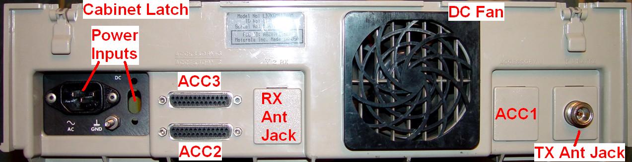
Accessory Jacks:
Both of these are DB25 female connectors. The upper connector is J3; the lower connector is J2. These are labeled with raised letters (which are very hard to see) on the back panel, shown here:
| Accessory Connector J2 - Remote Control, Paging, MRTI | ||
|---|---|---|
| Pin | Signal Name | Description |
| 1 | RX+ (LINE1+) [1] | Receive high used with L1473 (or similar) desk sets (TX and RX high for 2-wire operation; RX high for 4-wire operation) [1] |
| 2 | AUD_SHLD | Ground - audio or analog |
| 3 | TX+ (LINE2+) [1] | Transmit high used with all desk sets (TX high for 4-wire operation) [1] |
| 4 | MRTI_RX_AUD | Receive audio used for MRTI - discriminator audio [1] |
| 5 | A+ | +13.8 VDC or battery voltage |
| 6 | BUSY | Busy line of data bus; 5V logic |
| 7 | BUS+ | High side of bus data: 180° out of phase with BUS-; 5V logic |
| 8 | MRTI_AUD_CTRL [2] | Inhibits PTT from telephone interconnect when radio is receiving; 5V logic |
| 9 | VO1 | Vehicle interface output port 1 |
| 10 | PTT [2] | Push-To-Talk initiates a transmission; 5V logic |
| 11 | TX- (LINE2-) [1] | Transmit low use with all desk sets (TX low for 4-wire operation) [1] |
| 12 | DIG_GND | Ground for 5V logic signals |
| 13 | VI1 | Vehicle interface input port 1 |
| 14 | DGT_RX+ (SPKR_HI) [1] | Speaker high output (CAUTION: grounding this pin will result in damage to the radio) |
| 15 | DGT_RX- (SPKR_LO) [1] | Speaker low output (CAUTION: grounding this pin will result in damage to the radio) |
| 16 | RX- (LINE1-) [1] | Receive low used with L1473 (or similar) desk sets (TX and RX low for 2-wire operation; RX low for 4-wire operation) [1] |
| 17 | MRTI_TX_AUD | Transmit audio used for MRTI |
| 18 | VO3 | Vehicle interface output port 3 |
| 19 | BUS- | Low side of bus data: 180° out of phase with BUS-; 5V logic |
| 20 | RESET | Data bus reset line; 5V logic |
| 21 | 5V | 5V for logic circuits |
| 22 | VI3 | Vehicle interface input port 3 |
| 23 | VO2 | Vehicle interface output port 2 |
| 24 | MONITOR [2] | Disables PL signals to monitor carrier before transmission |
| 25 | NC | Currently not used |
RX+ and RX- are the received audio signal coming out of the station. TX+ and TX- are the transmitted audio signal going into the station. All of these are AC-coupled. The impedance selection switches above affect only the RX signals.
DC control would be implemented using the TTL-compatible PTT and MONITOR inputs. This requires more than one or two pairs of wires. It is NOT the same as the traditional DC current remote control commonly used with base stations.
LINE1+ and LINE1- are used for 2-wire operation. The impedance selection switches above affect only the LINE1 signals.
| Accessory Connector J3 - Physical Secure | ||
|---|---|---|
| Pin | Signal Name | Description |
| 1 | PS_AUD_IN | Transmit audio input to option L938 |
| 2 | ANA_GND | Ground - audio or analog |
| 3 | AUX_RX_AUD | Receive audio output from option L938 |
| 4 | DET_AUD | Detect or discriminator audio |
| 5 | A+ | +13.8 VDC or battery voltage |
| 6 | BUSY | Busy line of data bus; 5V logic |
| 7 | BUS+ | High side of bus data: 180° out of phase with BUS-; 5V logic |
| 8 | BUS_SHLD | Ground for data bus; logic ground |
| 9 | VSENSE1 | 10V line for option L938 |
| 10 | VSENSE1_SHLD | Ground for VSENSE; analog ground |
| 11 | NC | Currently not used |
| 12 | DIG_GND | Ground for digital circuits; logic signals |
| 13 | EMER | Activates emergency MDC1200 transmission |
| 14 | NC | Currently not used |
| 15 | NC | Currently not used |
| 16 | PS_AUD_OUT | Transmit audio output from option L938 |
| 17 | AUX_TX_AUD | Transmit audio output from option L938 |
| 18 | SWB+ | Switched +13.8 VDC or battery voltage |
| 19 | BUS- | Low side of bus data: 180° out of phase with BUS-; 5V logic |
| 20 | RESET | Data bus reset line; 5V logic |
| 21 | NC | Currently not used |
| 22 | SNET_LED | Lights when transmission is coded; +13.8 VDC |
| 23 | VSENSE2 | 10V line for option L938 |
| 24 | VSENSE2_SHLD | Ground for VSENSE; analog ground |
| 25 | NC | Currently not used |
Acknowledgements and Credits:
Much of this information came from the Spectra Desktop Base/Control Station Instruction manual, 6881081E65-C, still available as of July 2007 for about $20US. This revision includes an ASTRO Spectra supplement.
Spectra, ASTRO Spectra, Fascinator, MRTI, and probably a bunch of other terms are trademarks of Motorola, Inc.
Contact Information:
The author can be contacted at: his-callsign [ at ] comcast [ dot ] net.
Back to the top of the page
Up one level (Spectra index)
Up two levels (Moto index)
Back to Home
This page originally posted 08-Aug-07.
Article text, photographs, and hand-coded HTML © Copyright 2007 By
Robert W. Meister WA1MIK.
This web page, this web site, the information presented in and on its pages and in these modifications and conversions is © Copyrighted 1995 and (date of last update) by Kevin Custer W3KKC and multiple originating authors. All Rights Reserved, including that of paper and web publication elsewhere.