Up two levels (Moto index)
Go to the Home page
Front End Filter Response
By Robert W. Meister WA1MIK
|
Up one level (Spectra index) Up two levels (Moto index) Go to the Home page |
Spectra 900 MHz Receiver Front End Filter Response By Robert W. Meister WA1MIK |
|
900 MHz Spectra mobile radios are designed to receive 935-941 MHz and transmit 896-902 MHz and 935-941 MHz. Even though the radio is not designed to be a repeater receiver, people will try to use it for that purpose. Some may get it to work, others may not. Satisfactory results are usually not possible, but people will still try. Let's face it folks, 800 MHz MaxTracs, with shorted out or 915 MHz front end filters, are much better receivers at 902 MHz than any Motorola 900 MHz mobile radio. That's just the way of the world.
I can see that you still want to make it work. Even though I'm twisting your arm and doing my best to convince you that it's not possible, there are still those who need to be shown. What's necessary to get the radio to receive around 902 MHz?
There are three areas that need to be addressed:
I'll cover each topic below.
Receiver Front End:
The Spectra receiver front end has a six-pole ceramic filter that's huge in comparison to the ones in a MaxTrac. Each section is a 12x12x12 millimeter cube. In fact, this filter IS the entire front end of the radio. Here are photos of the top and bottom of the front end assembly (click on any image for a larger view):
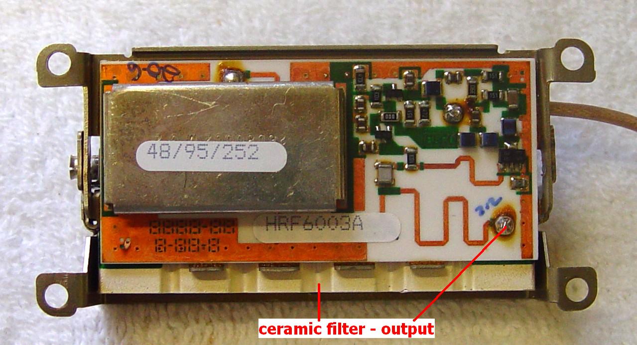
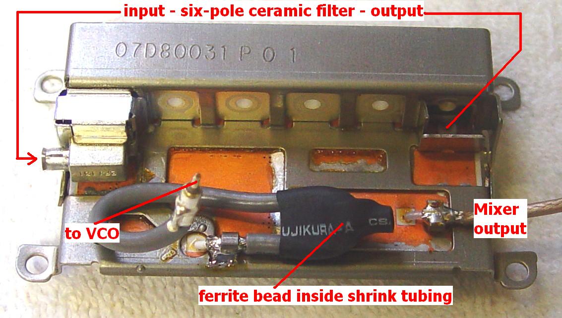
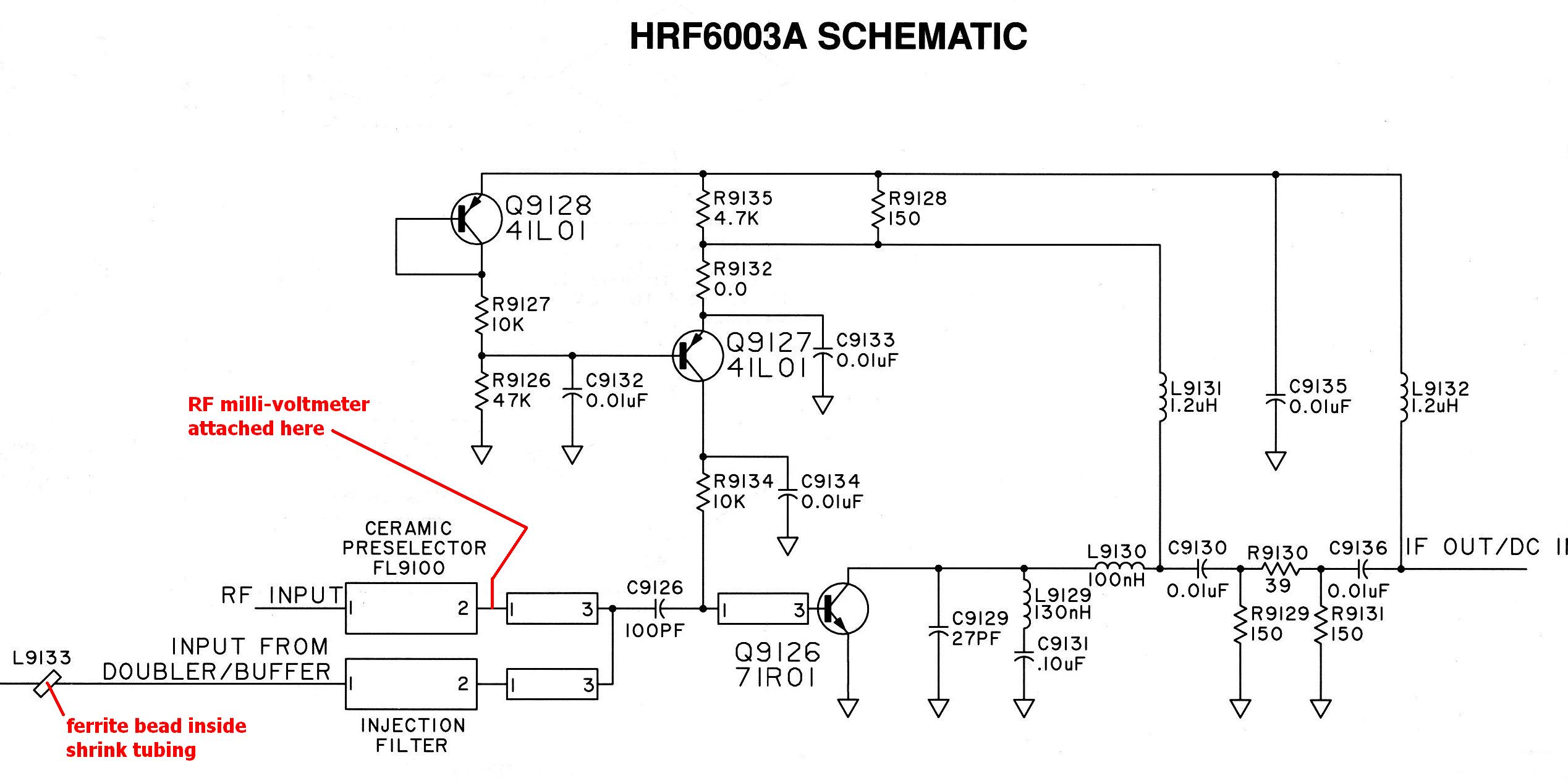
There is no amplification before or after the filter, and the mixer stage immediately follows it. This gives the radio great performance for the band it was designed to receive, with excellent image and interference rejection. Remember there are some high-power paging stations just below the voice band, so the radio needs all the selectivity it can get. A six pole filter is very tight; the MaxTrac has two three pole filters which are adequate for the task. Here's the schematic of the front end:
Measuring Front End Response:
I was going to measure the sensitivity of the radio at various frequencies and plot the results, but I was unable to come up with a modification to the programming software to let me enter a receive frequency below 926 MHz. Rather than beat my head over that, I moved to Plan B.
I connected an RF milli-voltmeter to the output of the front end filter, at the point noted in the schematic, and measured the response by sweeping it with my signal generator. Sounds good in practice, but I'm sure I made a mess of the filter's output impedance by soldering on about 15 inches of RG174. Anyway, this sort of worked, but I found that the mixer injection signal was feeding the same point and that gave me a residual reading that was about 15dB below what my signal generator could produce. Close, but no cigar.
I turned the radio off; that got rid of the mixer injection signal, but it also attenuated the filter output by several more dB. I swept it anyway by keeping a constant input signal level of about +17dBm and recorded the output of the milli-voltmeter. The results are plotted below:
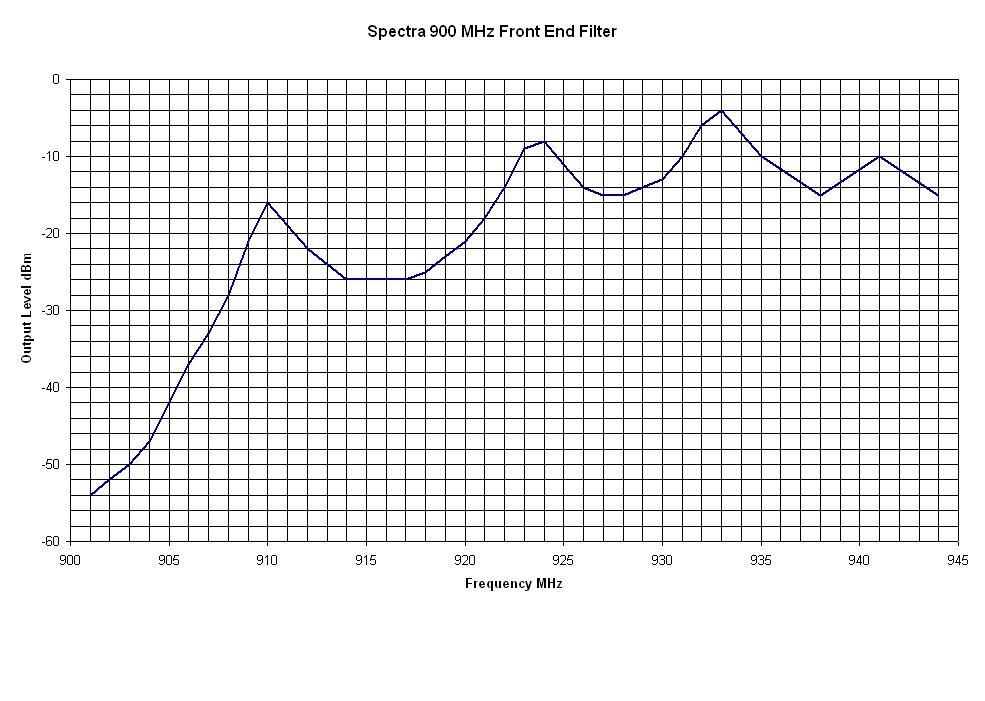
Note the various peaks in the filter's response. Some of this is due to the length of cable I had attached to the filter output to feed my meter. I'm sure there's some ripple in the passband; all filters have it, but I didn't choose to resolve the results that closely. In fact, I could change the meter reading by 10-20dB if I placed my hand on the coax cable or moved it significantly. Strange things happen to RF at 900 MHz.
You can see that things really start dropping off around 910 MHz but it's already getting pretty bad even at 916 MHz. That peak at 910 could be due to the test setup. By the time you get to 902, there's a good 50dB of attenuation, and likely more; my equipment was stretched to the limit to get even that kind of reading.
So, the Spectra has a nice sensitive receiver up at 927 MHz, but if it loses 50-60dB down at 902, you're not going to hear very much down there. So how bad IS reception at 902 MHz on one of these radios? Pretty bad. You'll need about 1 millivolt of signal for any kind of quieting, no where near 1 microvolt, which is what most repeaters have.
VCO:
The Voltage-Controlled Oscillator (VCO) operates in the 448-451 MHz band for transmitting (i.e. at 1/2 the carrier frequency), at 412.675-415.675 MHz band for receiving (i.e. at 1/2 the injection frequency), and at 467.5-471.5 MHz for talk-around transmitting (i.e. at 1/2 the carrier frequency). Doublers on the VCO board raise the signal to the exact carrier frequency for transmit, and to the mixer injection frequency for receive. The intermediate frequency on the RF board is 109.65 MHz. In order to receive 902 MHz, the VCO has to operate at ((902.00 - 109.65) / 2) or 396.175 MHz. This is quite a percentage of frequency change, and getting the VCO to lock at this low frequency may require playing with the steering line voltages by adding a resistor to the VCO, similar to what's involved in getting the radio to work on the amateur band in the first place.
Programming Software:
The RSS would have to be hex-edited to change the frequency ranges for the 900 MHz band, in at least two places, as follows (all numbers are MHz):
|
I tried to do this but was not successful. I even made sure the TX and T/A frequencies were lower than the RX frequencies; still it would not allow entry at 925 MHz. I'm sure it can be done, I just didn't want to spend more time trying. This is when I gave up and moved to "Plan B".
Conclusions:
So after doing all of this, what did I learn? Let's go back to the three areas of interest at the top of this article:
Well, two out of three isn't bad, but after doing the easy stuff, you still only have 1 millivolt sensitivity.
For most people, fixing all of these restrictions and obstacles is going to be impossible. In other words, IT WON'T WORK! It's really easier to convert an 800 MHz MaxTrac to do the job. They're cheaper, have similar specifications, and do work well as 900 MHz repeater receivers.
Equipment Used:
Hewlett Packard 3406A broadband sampling voltmeter
Agilent E4430B 1 GHz digital signal generator
Acknowledgements and Credits:
Spectra is a trademark of Motorola, Inc.
The schematic diagram came from Motorola's Spectra Detailed Service Manual and is used with their permission.
Photos were taken by the author.
Contact Information:
The author can be contacted at: his-callsign [ at ] comcast [ dot ] net.
This page was created 05-Jan-2007.
Back to the top of the page
Up one level (Spectra index)
Up two levels (Moto index)
Go to the Home page
Article text, photos, artistic layout, and hand-coded HTML © Copyright 2007 and date of last update by Robert W. Meister WA1MIK.
This web page, this web site, the information presented in and on its pages and in these modifications and conversions is © Copyrighted 1995 and (date of last update) by Kevin Custer W3KKC and multiple originating authors. All Rights Reserved, including that of paper and web publication elsewhere.