Up two levels (Moto Index)
Back to Home
And how to make your own tone elements
Plus a few notes on the HLN4020 dual-reed and HLN4181 reedless PL boards.
Compiled, HTML'd and Maintained by Mike Morris WA6ILQ
Photos by the author
|
Up one level (Mitrek index) Up two levels (Moto Index) Back to Home |
Secrets of the HLN4181 PL Board and the TRN4224 tone element And how to make your own tone elements Plus a few notes on the HLN4020 dual-reed and HLN4181 reedless PL boards. Compiled, HTML'd and Maintained by Mike Morris WA6ILQ Photos by the author |
|
| Note that the TRN4224 element is used on PL boards in a number of Motorola radios such as the Mitreks, Syntors, Maxar, Moxy, and more. While this page is Mitrek oriented, the information is applicable to the other radios as well. |
Comments and additional material are welcome
(even "Hey - you've got a typo at..." messages)
There was a discussion on the Mitrek HLN4181 reedless PL board and the associated TLN4224 tone elements on the repeater-builder mailing list a long time ago, and this writeup is a enhancement (in reality almost a total rewrite) of my posting on that topic... basically I deleted some irrelevant information and added some additional information I had since generated. The second major revision happened when I added the photos.
Note: When you print this file make sure that the diagrams below come out in a monospaced font (like Courier) if you want to see the diagrams below properly. I used an exclamation point as a vertical line since the actual vertical line character is one of the first ones replaced by a local language character in non-USA keyboards... I wanted this writeup to be as international-compatible as possible.
This writeup was generated from notes taken while working on a 40 watt UHF Mitrek and one each of the HLN4020 reed board and the HLN4181 reedless board as test beds, but since the PL boards are universal to all the Mitrek chassis the fact that I used a UHF radio shouldn't matter.
Note that the Mitrek is an all-metric radio - don't casually mix the leftover screws into your parts bin.
Another note... the UHF book that I have (6881045E70-A) is the only Mitrek manual I have found that has documentation on all three PL / DPL boards - the HLN4020 reed-type PL board, the HLN4181 element-type PL board and the HLN4011 DPL board. These three boards are completely interchangeable - the most you might have to do if you swap one board for another is to adjust the encoder level. The highband book I looked at seems to be incomplete - it was missing the HLN4020 reed-type board schematic. The low-band book I have in my file cabinet (a -O original version) has the HLN4020 reed board and the DPL 2-code adapter, but no DPL board or the HLN4181 reedless tone PL board. There may be later revision books that are more complete.
Note also that Moto uses a -O for the Original release of a manual, a -A is the first revision, and they work their way up the alphabet, skipping the letter O when they get to it. After -Z they continue with -AA, -AB, -AC, and so forth to AZ then BA...etc.
This web document started in late 1998 / early 1999 with a request for a TRN-4224 element for the HLN4181 PL board that was posted on the mailing list...
My response started with:
> I bought a tone element for 127.3 Hz from Telepath in San Jose (south of
> San Francisco in California) last week. They are at 800-292-1700, they
> take credit cards over the phone, and will ship parcel post, ground UPS,
> FedEx and next-day UPS.
> Obligatory disclaimer - I have no relation to them except as a satisfied,
> in fact, very satisfied, repeat customer.
--
For what it's worth, Telepath has since put up a web site at
http://www.telepathcorp.com.
2023 update: The Telepath I bought from folded, the Telepath of 2023 is a completely different
set of people that are using the sname name and web address. Your milage may vary.
The rest of my response to the inquiry was how to roll your own element from a few resistors, and was about half of the material that is below. Kevin W3KKC later emailed me and asked if I would write it up for his web site, so I did, and the first version was posted. That was over a dozen revisions ago. Happy reading!
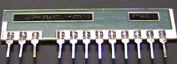
Photos of the two types of Mitrek tone PL boards (The HLN4011 DPL board is not shown). All connections to the board are made through the 9-pin connector header which looks like a vertical brown line at the right side of the photos (adjacent to a silver mounting screw). The strange shaped holes in the board provide tuning-tool access to adjustments in the receiver.
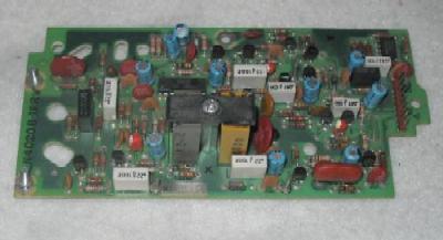 The HLN4020 reed-type board. The two reed sockets are at lower center, with the black plastic hold down arm above them. The KLN-6210 encode reed is on the left, the KLN-6209 decode reed on the right. There is no significance to the color of the housing of the reed. The right-side captive mounting screw is missing on this board. |
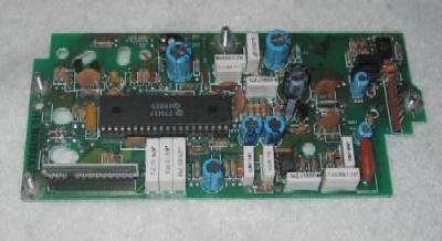 The HLN4181 reedless board. The long horizontal grey and white component at the bottom left is a TRN4224 tone element that is plugged into the black socket under it. |
The pinout of the brown single-row 9-pin connector at the right edge
of the photo above is:
Pin Function
1 = External tone in or out (depending on option jumpering)
2 = Squelch disable (via JU5)
3 = Tone encoder output to TX modulator
4 = PTT in
5 = Audio mute (via JU4)
6 = PL decoder audio input (from the receiver discriminator audio)
7 = PL filter
8 = B+ (pos 12v)
9 = gnd
Pin 9 is at the top, nearest to the only 8-pin integrated circuit on the board.
The earliest manual specified a pair of KLN6209 reeds for the HLN4020 reed-type board, and the later manuals specified one each KLN6209 (decode) and KLN6210 (encode) reeds. In perusing the schematic I did notice one nice feature that I've not seen in any other reed-based PL board, and that is that it can be jumpered to use one reed for a common encode/decode tone or two reeds for split tones. When two reeds are used the encode reed is on the left of the hold-down bracket in the above picture with the decode reed on the right, when one reed is used it goes in the encoder socket and two jumpers are added. The necessary jumpers are documented in the later schematics of the board (they are not included in the board revision D schematic but they are there are in revision F). An early board can be jumpered for single reed operation using the info from the later schmatic.
Should you wish to disable the reverse burst feature of the HLN4020 just lift one leg of CR4. Should you wish to change the duration of the reverse burst you can change the value of C31.
If you can't find the reeds you need on the frequency you need, the HLN4020 board seems to be just as happy with any of the following reeds (I've tried all of them at one point or another):
If you are looking for a HLN4181 board, at the time of this web page creation they were in stock for $20 each at C. W. Wolfe Electronics, a used 2-way radio dealer in Billings Montana at 406-252-9220. They also have the HLN4011 DPL board for $10. Note that this is not an endorsement of C. W Wolfe by myself or repeater-builder.com, I'm just mentioning it as a service. I have to say this - like I said in the above email I have no relation to Telepath or the C. W. Wolfe company except as a very satisfied repeat customer.
Note that the HLN4181 reedless board cannot do split tones due to it's inherent design - the circuitry can only decode the same tone as it encodes due to the fact that the encoder section is used as the frequency reference for the decoder. On the web page that I created describing how to interface a Mitrek to a repeater controller I've included a schematic of how to connect a separate encoder.
HOWEVER... If all you need is a different encode tone,
and can live with the decoder not decoding it's intended tone while transmitting,
well... looking at the HLN4181 schematic it appears that the custom chip that
is used on the board was designed to use two tone element sockets and switch
between them (look at pins 12, 13, 14, 15 and 16 of schematic 6880200W-06)...
Just tack a tone element socket (ordered from Moto as a replacement part
or scavenged from a dead board) onto the foil side of the board with a dab
of acid-free clear RTV, add some jumpers (I'd use wire-wrap wire)
to parallel all the pins except pins 1 and 2 to the existing socket, clone
the choke and resistor combination that is on pins 12 and 15 onto pins 13
and 14, and slave the "code select" pin to PTT (in the stock form the
pin is grounded, just unplug the chip, bend pin 16 to clear the socket, and tack
a piece of wirewrap wire to it and run it to a 22k pullup resistor and a
.05uf cap to ground, and to your PTT) .... Look at the schematic
and trace what I have written above... I've not tested this but it
looks like it should work...
Update: Look at the Syntor PL Board schematic - they use two sockets and
do exactly that.
The HLN4181 reedless board is very versatile and can be set up in many
unusual ways...
The normal jumpers are arranged like this...
| HLN4181 Reedless Mitrek PL Board normal jumpers | ||
| Jumper JU- |
Normal setup |
Function |
| 1 | OUT | Used to couple internal PL tone encoder to outside options |
| 2 | OUT | Disables the internal encoder when installed |
| 3 | IN | In to couple internal encoder to the TX modulator (and remove JU7) |
| 4 | IN | Install for "AND" squelch (and remove JU5) |
| 5 | OUT | Install for "OR" squelch (and remove JU4) |
| 6 | OUT | Install to disable PL decode (RX carrier squelch only mode) |
| 7 | OUT | In to connect external encoder to TX modulator (and remove JU3) |
| 8 | IN | Out to disable reverse burst |
| 9 | IN | When in couples RX audio into the PL decoder This jumper is not present in some early boards. |
| JU4 and 5 are redefined if the radio has the "Busy Light" option – see the footnotes on the schematics in the manual. |
||
| If your board has JU1, JU6 and/or JU7 in place, remove
all of them. If you want your PL decoder to work then JU9 must be in. If you want your PL encoder to work then JU3 must be in and JU2 must be out. |
||
Until I found the tone element I needed at Telepath, a friend of mine and I were reverse engineering the HLN4181 PL board and the associated TRN4224 tone element because we couldn't find a 127.3 Hz element in the junk boxes of any of the usual suspects, and in our application we absolutely had to have 127.3 Hz and we had to have reverse burst (which precluded tacking in a Com-Spec TS‑1 or TS‑32 as an encoder). We were 90%‑95% done when another friend found out about our project and called and told me about Telepath, gave me their phone number, said he had done a lot of business with them and was very happy with them. I called them, they had what I needed at a reasonable price, they had a couple of other items I wanted and hadn't been able to find anywhere else, so I gave them my credit card number and shipping address... Yes, at that point I knew enough about the board's design to make a 127.3 Hz element, but this was for a radio that was going to a repeater site that I can't get to very often. We were also in a bit of a rush, we had to get this unit in service in a couple of weeks - not much time for a burn‑in. All in all, for the cost of the element involved it wasn't worth risking a future middle‑of‑winter failure with a homebrew element... and other parts of the project needed the time we had left.
That caveat said, if you need to you can "roll your own" element with nothing more than a bunch of 1/4 watt, 1/8 watt or 1/10 watt 100k resistors (the smaller the physical size the better, there is no power being dissipated), some solder and some electrical tape. The TLN4224 element is simply a variable number of resistors (from 1 to 10 depending on the tone) that are used to program a counter.
In the process of reverse engineering the HLN4181 board my friend and I discovered that the tone generator is based on a 10‑bit binary counter that is preloaded with a number that is held by the element (see the schematic below) as two 5‑bit nibbles. The nibbles are selected by alternately strobing pin 1 or pin 2 of the element socket. Once the 10‑bit number gets into the counter it counts up to overflow then reloads the starting number and does it again... The higher the starting number the more frequent the overflow resulting in a higher tone frequency generated.
The encoder audio output is smoothed and filtered before injection into the transmitter. When the incoming PTT line goes inactive the encoder generates the reverse burst, then drops the outgoing PTT line. This takes care of the encoder function.
The decode function is accomplished by passing the raw receiver audio through a low-pass filter that passes only the PL frequencies. The result is fed to another part of the custom chip which uses the encoder as a frequency reference and checks for a matching frequency from the receiver audio. If there is a match it unmutes the receiver by way of JU‑4 or JU‑5.
There is also an audio notch filter on the board to remove the received PL tone from the received audio. However it's a pretty poor design and you don't want to try to use it in repeater service - just plan on using an external high-pass audio filter between the receiver and your repeater controller.
| Three images of the TRN4224 Mitrek reedless
PL tone element, I didn't have a digital camera at the time I created this web page (in 2002), so I used a friends flatbed scanner. |
|
 |
This scan is of the front of the TRN4224 element with a US ten-cent coin for size comparison. Pin 1 is on the right. The "114.8" is my own marking (done with an ultra-fine-tip Sharpie pen) on the ceramic. Every element, no matter what the frequency, has the same part number. If you find an element with a part number of TRN6005 you have a DPL code plug, which is used in the HLN4011 digital PL board. |
 |
This is the rear view of the same element,
just rotated 90 degrees and less the coin. In this photo pin one is at the top, and pin thirteen at the bottom. |
 |
This enlarged image shows how Motorola marks the PL tone elements with the frequency and tone code. I had to play with the brightness, contrast and gamma adjustments of the scanner software to get the printing in this image to show up at all, and even then it's not too visible. If you look very carefully at the top dark stripe you can see the vertical numbers 114(dot)8 in grey ink on a black background. The short dark stripe at the bottom says (vertically) "2A". On some of the elements the grey color of the ink blends into the dark epoxy stripe on the back of the element just a little too well. It takes better eyes than I have to read them without a magnifying glass, which is why once I know what the frequency is I label the front side of my elements with an ultra-fine-tip Sharpie pen. |
 Here's a better image of a 127.3 (3A) element. Click on the photo for a larger image. |
|
Note that on the TRN4224 tone element that there is no physical pin in location 4. In fact the socket has a plastic block there - it's used as a key to prevent people from inserting the element backwards. And while there is a pin in location 3 it is not actively used in the TRN4224 tone element (but it's grounded on the PL board). I'm assuming that it's connected to the substrate inside the tone element.
Internally the element and it's socket is set up like this (Each "Rx" is a position for either an open or a 100k resistor):
Here's an ASCII attempt at a schematic.
You will need a monospaced font (like Courier) to view it properly.
  +---------------------------------+--+----+----+----+
  !                                 !  !    !    !    !
  !   +-----------+---+---+---+-+   !  !    !    !    !
  !   !           !   !   !   ! !   !  !    !    !    !
  !   !          RA  RB  RC  RD RE  RF RG   RH   RI   RJ <-- 100k resistors
  !   !           !   !   !   ! !   !  !    !    !    !
  !   !           !   !   !   ! +-+-+  !    !    !    !
  !   !           !   !   !   !   !    !    !    !    !
+---+---+---+---+---+---+---+---+---+----+----+----+----+
! 1 ! 2 ! 3 ! X ! 5 ! 6 ! 7 ! 8 ! 9 ! 10 ! 11 ! 12 ! 13 ! <-- Mitrek socket pins
+---+---+---+---+---+---+---+---+---+----+----+----+----+
  !   !   !   !   !   !   !   !   !    !    !    !    ! <-- Mitrek PC board
  !   !  GND  !   !   !   !   !   W    !    !    !    !
  !   !       !   !   !   !   !        !    !    !    !
  ! strobe B  !   !   !   !   +--------+-X  !    !    !
  !           !   !   !   +-----------------+-Y  !    !
strobe A      !   !   +--------------------------+-Z  !
              !   +-----------------------------------+
              !   !
blocked pin --+   +-- data bits 6 and 7, chip pin 18
in socket           W=data bits 0 and 1, chip pin 22
                    X=data bits 8 and 9, chip pin 23
                    Y=data bits 4 and 5, chip pin 24
                    Z=data bits 2 and 3, chip pin 21
The RA-RJ references are not in the Moto manual, I assigned them just for this writeup to simplify things.
As you can see you can make your own element by inserting resistor leads into the socket and bussing the top leads of the two sets of resistors together and inserting the busses into pin 1 and pin 2.
My friend and I started with elements for the three different frequencies we had in stock, and determined the resistor pattern inside each element with a VOM (every resistor was about 100k, ranging from 85k to 115k, obviously not laser trimmed...), and created a table of tone frequencies versus data bits. We also determined that with no element inserted the encoder produced 273.3 Hz when the transmitter is keyed.
As another source of information in the reverse-engineering attempt we also used a single 100k resistor and inserted it into the socket pins - i.e. from pin 2 to pin 5 for resistor A, and noted the frequency that was generated when PTT was keyed, then from 2 to 6 for resistor B and remeasure, then from 2 to 7 for resistor C, all the way to resistor J from pins 1 to 13. We noted the frequency change that each pin produced by itself:
| ||||||||||||||||||||||||||||||||||||||||||||||||||
|
|
|||||||||||||||||||||||||||||||||||||||||||||||||
So pick a frequency, figure out what the difference between it and 273.3 Hz is, then figure out the bits you need to activate to get that difference, and program it in (or you can cheat and look at the table at the end of this writeup). Just plug the resistors into pins 5 to 13 and buss the appropriate top ends to pins 1 or 2. A flap of electrical tape over the strobe busses takes care of any insulation requirements. For pin 9 (resistors E and F) solder the two bottom leads together and clip one lead short – do not try to plug both leads into the pin in the socket. If you want some physical rigidity slop a big glob of some acid-free clear RTV onto the resistors. If you want some shielding (usually not required) just fold a flap of copper foil (available at model airplane hobby shops) over the hardened RTV and solder a trimmed piece of a resistor lead (or a short piece of #24 wire) to it and plug the wire tail into pin 3 (ground). If you chose to use RTV, make sure you get the acid-free clear RTV – check the label! – most of the common brands give off acetic acid as they cure and that will eat up your solder connections - and the damage will be hidden inside the hardened RTV ! (This is the voice of experience speaking about some Permatex #66)... Just loosen the cap on the RTV and sniff... if it smells like vinegar then don't use it!
One advantage to the HLN4181 - you can have a Mitrek on each end with NO tone element installed (i.e. set to 273.3 Hz, a non-standard tone) and they can talk to each other. The higher frequency tone also means minimum pickup delay. This is ideal on point-to-point links (and it saves having to make up any elements). Yes, the 273.3 Hz tone is harder to filter out of the audio than a lower frequency, but it can be done with an active filter (i.e. a switched capacitor notch filter). The simplest element that gives you a standard tone is a resistor from pin 1 to pin 5 for 229.1 Hz, but that's a pretty high frequency and not every radio can filter that out. The second simplest is a resistor from pin 1 to pin 9, and a second one from pin 2 to pin 10. That gives you 136.5 Hz (4Z) but any DPL on the channel could kerchunk it. The one I use the most is three resistors, the first from pin 1 to pin 6, and the other two from pin 2 to pins 10 and 11 for 127.3 Hz.
The HLN4181 PL board also allows you to pick weird or non-standard tones in 0.3 Hz steps from 273.3 on down, but to make them workable you need these PL boards on both ends... this trick can be handy on point-to-point links that you want to keep the riff-raff out of (if you don't mind the PL pick-up delay - a lot of links use carrier squelch to minimize the pick-up delay that comes from cascaded links). Maybe 199.1 Hz anybody? Or 235.0 Hz ? However, you have to remember that PL (or Digital PL) doesn't solve interference issues, it just covers them up. Sure, the RX won't unsquelch if it is requiring a weird tone and the local idiot only has the standard tones but the idiot can still sit there and transmit on the channel causing a heterodyne or capturing / blocking the receiver, so what real security (or increase in usability) have you really gained ? And what prevents a determined and resourceful idiot from listening to you on the input with an OptoElectronics tone grabber (or a desktop or laptop computer running a sound card frequency counter, or a waterfall display audio spectrum analyzer) and finding your weird magic tone ? (that takes maybe 2‑3 seconds of signal). But if you feel like playing around with this concept you can also build up a test jig by taking ten resistors, a ten-position DIP switch and some wire and hooking them up as follows:
+-----------------------------------+--+---+---+---+
!                                   !  !   !   !   !        !
!   +-----------+---+---+---+--+    !  !   !   !   !        O
!   !           !   !   !   !  !    !  !   !   !   !         \
!   !           O   O   O   O  O    O  O   O   O   O        O \ is one pole
!   !            \   \   \   \  \    \  \   \   \   \       !   of a DIP switch
!   !           O \ O \ O \ O \O \  O \O \ O \ O \ O \
!   !           !   !   !   !  !    !  !   !   !   !
!   !           !   !   !   !  !    !  !   !   !   !
!   !          RA  RB  RC  RD  RE   RF RG  RH  RI  RJ <-Tone element
!   !           !   !   !   !  !    !  !   !   !   !    resistors
!   !           !   !   !   !  +-+--+  !   !   !   !
!   !           !   !   !   !    !     !   !   !   !
--+---+---+---+---+---+---+---+-----+---+---+---+---+
1 ! 2 ! 3 ! X ! 5 ! 6 ! 7 ! 8 !  9  ! 10! 11! 12! 13! <--PL tone element socket pins
Here's a table / drawing that might make it easier. Verify the tone generated after you plug the resistors into the socket. You can juggle the tone frequency in 3-tenths-of-a-cycle steps... (see the frequency difference table above).
You will need a monospaced font (like Courier) to view this diagram and table.
+-----------------------------------+---+---+---+---+
!                                   !   !   !   !   !
!   +-----------+---+---+---+--+    !   !   !   !   !
!   !           !   !   !   !  !    !   !   !   !   !
!   !          RA  RB  RC  RD  RE   RF  RG  RH  RI  RJ <-Tone element
!   !           !   !   !   !  !    !   !   !   !   !    resistors
!   !           !   !   !   !  +-+--+   !   !   !   !
!   !           !   !   !   !    !      !   !   !   !
--+---+---+---+---+---+---+---+-----+---+---+---+---+
1 ! 2 ! 3 ! X ! 5 ! 6 ! 7 ! 8 !  9  ! 10! 11! 12! 13! <--PL tone element socket pins


FREQ   CODE    RA  RB  RC  RD  RE  RF  RG  RH  RI  RJ
67.0    XZ      -   X   -   X   -   X   X   -   -   -
71.9    XA      X   -   X   -   X   X   X   X   -   X
74.4    WA      X   -   -   -   -   X   X   X   X   X
77.0    XB      X   -   -   -   -   -   X   X   -   X
79.7    WB      X   X   X   -   -   X   X   -   -   X
82.5    YZ      X   X   -   -   -   -   X   -   X   X
85.4    YA      X   -   -   -   X   -   X   -   -   X
88.5    YB      -   X   X   -   X   -   X   X   -   X
91.5    ZZ      -   -   -   -   -   X   X   X   X   X
94.8    ZA      -   X   X   -   X   -   X   -   X   X
97.4    ZB      -   X   X   -   -   -   X   -   -   X
100.0   1Z      -   -   -   -   -   X   X   -   X   X
103.5   1A      X   X   X   -   X   -   X   X   X   -
107.2   1B      X   X   -   -   X   X   X   X   X   -
110.9   2Z      X   -   -   -   X   -   X   X   -   -
114.8   2A      X   -   X   -   -   X   X   -   -   -
118.8   2B      X   -   -   -   X   X   X   -   -   -
123.0   3Z      -   X   X   -   -   -   X   X   -   -
127.3   3A      -   X   -   -   -   -   X   X   -   -
131.8   3B      -   -   X   -   X   X   X   -   -   -
136.5   4Z      -   -   -   -   X   -   X   -   -   -
141.3   4A      X   X   -   X   X   X   -   X   X   X
146.2   4B      X   X   X   X   X   -   -   -   X   X
151.4   5Z      X   -   -   X   X   -   -   -   X   X
156.7   5A      -   X   X   X   X   -   -   X   -   X
162.2   5B      -   -   -   X   X   -   -   X   -   X
167.9   6Z      -   -   -   X   X   X   -   -   X   X
173.8   6A      X   X   X   X   X   -   -   X   -   -
179.9   6B      X   X   X   X   -   X   -   -   X   -
186.2   7Z      X   X   -   X   X   X   -   -   -   -
192.8   7A      -   X   -   X   -   X   -   X   X   -
203.5   M1      -   X   -   X   -   X   -   -   -   -
206.5   8Z      X   -   X   -   -   X   -   X   X   X
210.7   M2      X   -   -   -   X   X   -   X   X   X
218.1   M3      X   X   -   -   X   X   -   -   X   X
225.7   M4      -   -   X   -   -   X   -   X   -   X
229.1   9Z      X   -   -   -   -   -   -   -   -   -
233.6   M5      -   -   X   -   X   -   -   X   -   - **
241.8   M6      X   X   X   X   -   -   X   -   -   - **
250.3   M7      X   -   X   -   X   -   X   -   -   - **
254.1   0Z*     X   X   X   X   X   X   -   -   -   - **

   Socket Pin   5   6   7   8   9   9  10  11  12  13
       Strobe   2   2   2   2   2   1   1   1   1   1
    Resistors  RA  RB  RC  RD  RE  RF  RG  RH  RI  RJ
Notes:
1) * The Motorola name for this tone is "zero-Z" due to the unfortunate truncation
of "10Z" into a two character field.
2) ** The last four are courtesy of James Nelson KE4GWW (his-callsign@arrl.net)
Use any of the tones above 203.5 Hz only if you are absolutely sure that all of your users radios have those tones. Depending on the manufacturer many do not, or can have different combinations of them. Those that do have the higher tones frequently stop at 250.3 Hz and finding the 254.1 Hz tone in service is really unusual. In other words, everything above 203.5 Hz should be assumed to not be available to the average repeater user.
Good luck and after you get your Mitrek going please drop me an email and let me know how things went. I've spent a lot of time on the original engineering, the original notes, this web page and the revisions and updates (over a dozen of them), and sometimes I wonder if anybody is actually reading these missives to the masses...
If you see something above that is vague, missing (or outright wrong), please let me know! It's input from the readers that make these writeups better - I've probably either totally missed or shortchanged topics and / or subtopics that really need to be covered.
Contact Information:
The author, Mike Morris WA6ILQ, can be contacted here.
Back to the top of the page
Up one level (Mitrek index)
Up two levels (Moto Index)
Back to Home
This article was originally engineered and written in January 1984 for a
copyrighted article for an amateur radio club bulletin.
That article rehashed and this web page created early August 2002,
and first posted on 14-Aug-2002
This web page is copyright © Michael R. Morris WA6ILQ 2002 and the date of the last update. It was derived from a typewritten document created in 1984.
This web page, this web site, the information presented in and on its pages and in these modifications and conversions is © Copyrighted 1995 and (date of last update) by Kevin Custer W3KKC and multiple originating authors. All Rights Reserved, including that of paper and web publication elsewhere.