Note that the CM / PR radios have a MUCH smaller heat sink and hence are a MUCH lower duty cycle radio. Moto also made a digital / DMR variant of the CM series... Your author has seen the CM200D and CM300D, but has not had the opportunity to bench one.
Any other details on USA versus non-USA models would be welcome.
A comment on the Mini UHF connector from a friend:
Especially in mobile service a lot of installs or sloppy loose attachment by service techs ends up putting side pressure on the center pin. This will spread the female contacts in the radio connector. Visually inspect, and see if your connection acts at all flaky. The CDM antenna connector is replaceable, but its NOT a job for the faint of heart, or those inexperienced in soldering. It is best to use a dental pick or similar and get at the tines in the female and "encourage" them inward to make a tighter connection. DO NOT get carried away and break one of the tines.
An acid test: Take a unused male pin out of a connector kit, stick it into the radio connector, and turn the radio vertical with the antenna connector facing down. See if the pin falls out.
- The RKN4083A is Moto's official 8 pin CDM/CM200/CM300/PR400 series RIB-based programming cable, and the RKN4081C is the ribless version. I suspect either will work on the M1225, R1225 and XPR series as well. The RIBless cable has a 25 pin female connector (there's a circuit board inside), needs (and comes with) a 25"pin to 9"pin adapter. The RKN4081C cable sells for about $250-$300 and is here: photo 1 photo 2 photo 3 photo 4
Honestly, for everyday programming (i.e. never flashing firmware) just get your choice of a 8 pin programming cable (either DE9 or USB) from KJ6ZWL. If you are going to use a USB cable then a FTDI based cable is preferred over a Prolific based cable.
The RLN4853 adapter (PDF) (photo) allows the RKN4081 cable to be used to program the CDM series through the accessory connector. Build one yourself from the photo, it's nothing more than a RJ45 female connector, a length of 4-conductor cable, and a 20-pin accessory connector... the schematic is on page 2 of the PDF. - The RLN4781A is a bracket that mounts a VHF/UHF CDM into a standard auto radio DIN opening. It's widely used in the UK and Europe for mounting the radio into a taxi or shuttle bus dashboard.
- The GLN7324A is the standard mobile bracket. It fits the CDM (except low band), the GTX, the CM and the PRO5100 and 7100. The low-band CDMs are larger and use a larger bracket, the RLN4774A.
- Moto's accessory sheet mentions the RSN4001 as an amplified external speaker for loud environments (black). There's another one in a different color (brown?) but I don't have that part number. Of course you can always use a GM300, Micor or Motrac mobile speaker.
- The factory Ignition Sense cable is the HKN9327. It has an ATO fuse holder in line and ships with a 4 amp fuse. Ignition sense pulls milliamps. Personally, I'd use a 1/2 amp if I could find one, or a 1 amp if that was the smallest I had available.
- The factory Motorola 12VDC 10A switching power supply for the CDM, XPR, GTX, CM / PM, Maxtrac or Radius series was either the HPN4001B for the high power radios (which was discontinued and replaced by the HPN4007) or they offered the HPN4002B for the low power radios.
- The HKN4137 (superceeded by the HKN4139) is the recommended mobile power cable for low power radios. It is 3 meters (9.8 feet) long, uses 14 gauge wire and ships with a 15 amp ATO fuse / holder in line.
- The HKN4191 is the recommended mobile power cable for high power radios. It is 3 meters (9.8 feet) long, uses 12 gauge wire and ships with a 20 amp ATO fuse / holder in line.
- The HKN4192 kit is recommended for higher power radios. It is 6 meters (19.6 feet) long, uses 10 gauge wire and ships with a 25 amp ATO fuse / holder in line. You will want to use one of these for the low band CDMs.
- The factory tabletop tray is a GLN7326A. It has a front-facing speaker in the bottom, the GLN7318 is the same plastic tray but without the speaker.
- Astron sells the SL-15SCDM 15 amp desktop radio housing / power supply.
- Samlex offers two different housing / power supply units for the 750, 1250 and 1550 series: the SEC-1212-CDM (12 amp) and the SEC-1223-CDM (23 amp).
- The firmware loading adapter for a CDM is a HLN9742. If you don't know what it's for or don't know you are doing then you don't need it. If you do need one you can build from the schematic on page 4... Or just look at the schematic and add a center-off SPDT switch into your RIB.
Follow the directions on the screen of the firmware flashing program to put the radio into boot mode... Position "A" grounds pin 25 on the adapter (for flashing handhelds, and CDM's through the rear connector). Position "B" connects connects 12 to 25 (flashing CDM's from the microphone jack - it shorts pins 5 and 6 on the mic jack. On the flash adapter, you use the "A" position to put the radio into bootstrap mode when flashing through the accessory connector, and the "B" position when using the mic jack. - Novexcomm sells a dual CDM rack mount chassis that is available with or without your choice of a 15 amp 120vAC supply or a 30 amp 120 / 240v power supply. They will also make it with your choice of radio cutouts.
Disclosure: your page author has known the owner of Novexcomm (WB6SLC) for 40+ years.
| Component | TE-Amp | Digikey | Mouser | Notes |
|---|---|---|---|---|
| 16 Pin Housing | 104422-1 | 104422-1-ND | 571-104422-1 | Maxtrac, Radius LRA, M10, M120, M130, GM300 |
| 20 Pin Housing | 104422-2 | 104422-2-ND | 571-104422-2 | CDM series |
| Female Pin | 86016-2 | A25989-ND | 571-860162 (loose pins) or 571-85969-8-CT (a strip of 100 pins) |
I've provided two part numbers for the Mouser pins as sometimes the loose individual pins are out of stock when the strip of 100 pins is available (100 pins is the smallest bulk amount). |
A wide variety of 16- and 20-pin connectors and connector / interfacing kits / cable kits can be purchased from ebay seller "mre1032" (Kurt Meltzer, KC4NX / WB9KNX, Meltzer Radio Engineering).

| ||||
| Pin | Description | Direction | Comments | Simple Interface |
|---|---|---|---|---|
| 1 | Speaker (-) | Output Only | Not Programmable. DO NOT accidentally ground this pin! Doing so will damage and probably destroy the speaker amplifier. | Program the minimum speaker level to zero. |
| 2 | External Mic Audio | Input Only | This pin is high-pass filtered and programmable for emphasis or no emphasis. Input impedance is 560 ohms. Depending on the Tuning settings the deviation on this pin can be limited to a max of about 4 KHz. | Transmit audio input (default is with emphasis). |
| 3 | Digital In #1 | Input Only, Active Low Only | Fully Programmable, one option is external microphone PTT. | PTT (to ground) |
| 4 | Digital In #2 | Output Only | Fully Programmable. Note: this pin is the only one that actively pulls high, and can handle a small relay coil (don't forget the shunt diode), all the other output pins pull low (to ground). | |
| 5 | Flat TX Audio Input | Input Only | This pin is always flat, is not highpass filtered and is used as a PL input, DPL input, digital paging data input, LTR digital data input, etc. Input impedance is 560 ohms. Note: there is NO deviation limiting on this pin. You must use a service monitor to watch the deviation while setting the input level to this pin. |
Optional: Connect to an external PL, DPL or paging encoder. |
| 6 | Digital In/Out #3 | Input Only | Fully Programmable, includes Channel Select | |
| 7 | Ground | Ground | ||
| 8 | Digital In/Out #4 | Selectable I/O | Fully Programmable, includes Channel Select | COS out |
| 9 | Analog In #5 | Special Input, Tri-state Emergency Switch | Programmable, however the only options are Null and External Emergency Switch (Input) | See note below. |
| 10 | Ignition Sense | Special Input | Not Programmable, Active High only. If you use this pin you should fuse it with a 1 amp (or smaller) fuse! See the notes further down on this page. |
|
| 11 | Receive Audio Output | Output Only | Partially Programmable. This pin can be programmed to output either flat or
de-emphasized receive audio. Note that like the CDM, like the Maxtrac, Radius and GM300 series, provides squelch-muted, PL-filtered and de-emphasized "handset audio" on one pin of the microphone jack. |
Receive audio output (de-emphasized). |
| 12 | Digital In/Out #7 | Selectable I/O | Fully Programmable, includes Channel Select | |
| 13 | Switched Battery | +12v out to accessories when the radio is powered on. | Not Programmable. This pin can source up to 1 amp (from a dedicated LM2941 regulator
inside the radio). If you use this pin then make sure you fuse it with a 1 amp (or less) fuse! |
|
| 14 | Digital In/Out #8 | Selectable I/O | Fully Programmable, includes Channel Select | Optional: CTCSS decode out. |
| 15 | RSSI (Received Signal Strength Indicator) |
Analog Voltage Output zero to 2.4 volts DC |
Not Programmable NOTE: On the Maxtrac / Radius LRA / GM300 series this pin was the speaker and was normally externally jumpered to pin 16! |
If your controller has an extra analog input connect this to it. |
| 16 | Speaker (+) | Output Only | Treat this pin the same as pin 1 | |
| 17 | BUS (+) | Bidirectional | Not Programmable. | You can program the radio through this pin. |
| 18 | Boot Control | Special Input | Not Programmable. To enter Boot Mode this line must be connected to ground when the radio is switched on. | |
| 19 | Pins 19 and 20 are labeled as NC (No Connection) on some documentation, and "Reserved" on others... | But... the Detailed Service Manual shows pn 19 as "UART-RX" and 20 as "UART-TX" on the diagram labeled "Controller T2 Schematic Diagram - I/O". These same signals connect to the controller and I/O chips on the diagram labeled "Controller T2 Schematic Diagram - Controller Overall" and to the UART chip on the "Controller T2 Schematic Diagram - Microprocessor" schematic. | ||
| 20 | ||||
- Like the Maxtrac / Radius LRA / GM300 series an external loudspeaker can be connected to the Accessory connector pins 1 and 16. The speaker inside the CDM control head is designed to be able to be unplugged when an external speaker is used.
- Ground pin 9 (i.e. jumper to pin 7), and program it for Emergency, but do not define the energency condtion. This programming will force the radio to turn itself on when power is applied.
- Pin 15 used to be a speaker connection on the GM300 and earlier radios. It is now "RSSI" (Received Signal Strength Indicator), an analog output that varies from zero to +2.4 volts DC. If you reuse your old GM300 acccessory cable then the pin 15 to 16 speaker jumper must be cut. The RSSI output is unprotected and is fed from a pin off the SA616 IF integrated circuit. According to the datasheet, it is calibrated and temperature compensated to within 2 dB over an 80 dB of range. The CDM service manual calls this a linear range from ‑120 to ‑55 dBm of input signal.
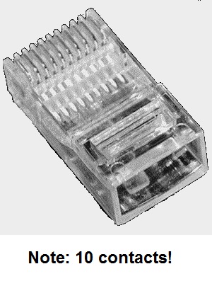
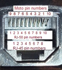
| Microphone Jack | Microphone Jack Pin Description | Accessory Plug Pin | Comments | ||
|---|---|---|---|---|---|
| Moto Pin # | RJ-45 Pin # | RJ-45 Wire Color (Body / Stripe) | |||
| 3 | 6 | Orange / White | Hookswitch | 6 | Assign this pin to Hookswitch function in RSS / CPS. Not every application that needs a rear panel connected microphone will need this pin. |
| 4 | 5 | White / Blue | Ground | 7 | |
| 5 | 4 | Blue / White | Microphone Audio High | 2 | Program with emphasis enabled in RSS / CPS. |
| 6 | 3 | White / Orange | EPTT | 3 | Assign this pin to External PTT in RSS / CPS |
| 7 | 2 | Green / White | BUS (+) | 17 | Optional: If you add this connection then you can program the radio through this connector / cable. |
| (none) | (none) | (none) | Boot Control | 19 | Optional: If you add a switch from this pin to ground then you can load new firmware into the radio through this connector. |
Radio Configuration -> Accessory Pins tab -> Accessory Package: Default (which makes accessory connector pin 3 an External Mic PTT Input, Active Level = Low, and Debounce Enable checked).
Radio Configuration -> Accessory Pins tab -> Set pin 6 as Mic Off Hook (Input), Active Level = Low, and Debounce Enable checked.
Then Radio Configuration -> Accessory Configuration tab -> set External PTT Audio Source: Ext Mic Audio
Note that the CM / PR radios have a MUCH smaller heat sink and hence are a MUCH lower duty cycle radio. Moto also made a digital / DMR variant of the CM series... Your author has seen the CM200D and CM300D.
Recommendation: On every CDM you want to use the latest firmware your radio will accept. Save the original codeplug that came with the radio and back up your tuning data (you will need the Tuner program to do that). You never know when you might need them. A firmware upgrade to a Waris radio will not change the tuning information. I repeat: Before you do anything to a new-to-you CDM you need to save the original codeplug it came with AND use the Tuner program to save the tuning data.
One caution: Do not let the power fail while programming the radio, ESPECIALLY while loading firmware. When programming a CDM, Pro or Expert series handheld or mobile radio do NOT touch anything until you get the second set of beeps after loading a codeplug. The radio will beep when the programming load is complete, then the radio will reset itself and restart. That restart concludes with another beep. WAIT for that post-restart beep! If you start unplugging cables or shut off the power in-between the beeps you stand a good chance of corrupting the radio...
Second caution: This was mentioned above, but disconnect any dual head kits or remote kits while programming. Use a local head only.
If you end up with a password protected radio and don't need to save the original frequencies, the easiest way to bypass the password is to just load a non-password-protected codeplug over the passworded one. !!The model number must be exactly the same!! If you don't have or can't get a a non-password-protected exact same model number codeplug then load a blank codeplug into the radio using your CPS. If you need a blank codeplug there is a folder full of them, one for each possible model number in the SAMPLES directory of your CPS (but if you are going to be unlocking password protected radios you will want a copy of the SAMPLES directory from the last / final revision as there are a model numbers that are not in previous versions).
There is an alternate method that will bypass the password and will let you view or overwrite the existing codeplug, but it requires knowledge and experience in hex editing the CPS executeable file. If you know what you are doing in hexediting use CPS 6.12.05 and open ProRadio.exe, then change offset 24DD69 from 74 to EB then save. Then when the CPS asks for a password don't type anything, just hit Enter. Naturally, make a backup copy of your CPS first. What I do is rename the ProRadio.exe file to ProRadio.backup.exe, then open it, then save it as ProRadio.exe, then hexedit it, then save it again. If you have a different revision look for the string 5B85C0742B and change it to 5B85C0EB2B (only the second last byte of that new string is different). Then run your hexedited CPS and when it asks for a password just hit "Enter".
Note: Your author does not have any hands-on experience with the low band radios at the time of this writing.
I'll repeat myself - If you find one cover screw loose, back them all off a turn or two and then torque in the numbered order.
If you have to open the radio then open it in reverse order and do not forget to pull the black accessory plug housing out of the back of the chassis before lifting the board out of the housing. When installing the top cover, lightly run the screws in first to position and settle the plate, then torque them in numerical order as outlined in the manual. This is necessary to insure proper pressure on the thermal pad for the PA and other heat generating devices inside.
|
|
The CDM Product line, like every LMR radio made in the last 20+ years, is switchable between wideband and narrowband... The CDM receiver uses a 15 KHz filter in the first IF followed by a 15 KHz filter in the second IF which is followed by a third filter. The third filter in the VHF and UHF CDM is switched between narrow and wide.... EXCEPT... The "200 MHz" CDMs and the 700 MHz CDMs were made for spectrum that had never been wideband. Those two models were locked to narrowband 2.5 KHz TX deviation and 12.5 KHz channel spacing from the factory. They have no switching, there is no wide filter... they actually left out the wideband receive parts as the circuit boards were assembled. Since most 220 MHz ham rigs exceed 5 KHz deviation from the factory the narrowband "200" MHz CDM receiver will see a normal signal as an overdeviated signal and squelch out. There is a fix... Note that if you are using 200 MHz CDMs as both ends of a point-to-point link between, for example, a "hub" repeater and a number of "spoke" repeaters you won't need to do the fix...The hardware fix for the 200 MHz CDM is to simply change out the last filter from a narrowband part to the correct wideband part and then do a full wideband receive alignment. Fortunately the transmit circuitry will support wideband without any component changes but the wideband transmit alignment must be done. Background info: A Murata "D" series is 20 KHz wide (actually +/- 10 KHz, an "E" series is 15 KHz wide (actually +/- 7.5 KHz), an "F" is 12 Khz wide (actually +/- 6 KHz), and a "G" is 9 KHz wide (actually +/- 4.5 KHz).You will find the Murata CFWC455G filter in the stock 200 MHz CDM, specifically Motorola part number 9180469V03, installed in the radio at location FL304 or FL3106 (depends on the board and manual revision), it's the last filter in the IF section. You need to replace that filter with the equivalent wideband version - in the low band, VHF and UHF models Moto used part number 9180469V05 (a Murata CFWC455E). At the time this page was written Moto Parts says that exact part is NLA (No Longer Available)... it used to be between $12 and $15 each. So you'll have to salvage it from a low band, VHF or UHF hulk (not easy to remove the one from the hulk without the correct surface mount desoldering equipment), or find an electrically similar 4-pin filter and install it... Once you get the wideband IF filter installed you get to do a full wideband receive alignment. |
|
|
Changing the Band Edges... The stock "200" MHz CDMs came from the factory covering 217-222 MHz. These can be "stretched" to cover the 222-225 MHz (or 219-225 MHz, your choice) amateur radio band. They can also be convinced to use 20 KHz channel spacing instead of the 12.5 KHz it was shipped with. It's all done in software... specifically tweaks to the codeplug. Note that once you change the band edges or the channel spacing you won't be able to use any previous codeplug or stored tuning data from the radio. So save a copy of the tuning information. Just in case... No, you don't need to reinvent the wheel, it's already been done and a sample codeplug is "out there" on the internet. And once the radio is happy with the band edge changes and the channel spacing then you need to use the Tuner program to save the tuning data. Just in case. I'm going to repeat myself: Before you do anything use the Tuner program to save the tuning data. Now you can use use stock unmodified "Pro series" Ver 6.12.05 (or later) CPS software to program the radio. |
Naturally you will have to connect a head while programming the radio. During that programming session you will be entering your frequencies and PL / DPL, and other features. The programming options under "Radio Configuration" include "Ignition Sense Type:", with the options of:
1) Disabled
2) Follow Ignition Only
3) On/Off and Ignition
4) PTT Disabled (i.e. a receive-only radio)
A blown Ignition Sense input is a known issue with the CDM mobile radios. If the voltage on the Ignition Sense pin spikes high or low it can kill the ignition sense function so it no longer works. Sometimes it can be fixed (replace diode D0660 and D0661, both are a 3-legged dual diode, part number 4813833C02), other times not. If the radio is programmed for Follow Ignition Only and the Ignition Sense input to the microprocessor is blown then you can't power up the radio and YOU ARE SCREWED.... off to the depot. But there is no more flat rate depot repair, support has ended. You now have a lightweight doorstop, and it's due strictly to how you programmed the radio.
You can wire the Ignition Sense (pin 10) in parallel with the DC power input. When the DC power is switched on then radio will automagically come on. But that leaves the fragile Ignition Sense line exposed to the outside world. If you do, you should include a 1 amp (or smaller) fuse in the line. Don't forget that fuse! Some CDM circuit board vintages have a 15 volt zener diode on the Ignition Sense line to shunt any overvoltage to ground. When that diode conducts it can pass enough current to melt the copper trace on the circuit board open. Sometimes you can fix the blown trace, sometimes not.
Update: Depending on the firmware the "External Emergency Switch (Input)" (pin 9) on the CDM accessory plug includes a "wakeup" feature, so if pin 9 is grounded momentarily (to pin 7), the radio will turn on and switch to emergency mode. The only options for pin 9 are Null and Emergency, so it is rarely connected, programmed or used. If the radio is not programmed for emergency, it will do nothing but turn on. This feature will simply provide a "back door" method to power up the radio. Once it's on you can reprogram the radio to On/Off and Ignition, then use the radio as a mobile or a base station. Or fix the zapped pin 10.
Watch out when using ignition sense on CDM's! We had a customer with several radios with dead ignition sense pins, some were from vehicles that had been jump started and some were not. The radio dies when the ignition sense line gets a negative voltage spike, usually from a heavy-duty power solenoid (e.g. starter solenoid). This negative voltage spike exceeds the PIV rating of the diode, and the diode usually opens. When the diode does not open, this spike goes to the CMOS microprocessor, and if it jumps even one metal-oxide junction the result is fatal. The HLN6325 diode kit is designed to short this spike to ground before it enters the radio.Could someone scan the paperwork shipped with the HLN6325 diode kits? Does anybody have a PDF of that SRN?
We eventually found a Motorola Service and Repair Note (SRN) for the CDM series that said vehicles using large power solenoids, that have the ignition sense connected to the solenoid, can produce negative voltage spikes that can blow out some parts in the radio. Since then, we always install CDM ignition kits with HLN6325 diode kits.
Here's one emailed response:
IF you have a CDM wired up through the accessory connector to an external controller, and you have Ignition Sense set to the default ON/Off OR Ignition there is a potential problem. If you push the front panel on-off button while the external controller has the radio transmitting then the radio will APPEAR to turn off - BUT IT DOES NOT TURN OFF! It goes into an uncontrolled mode and draws several amps. This is VERY messy. Usually you have to make a trip to the site and unplug power from the radio to clear the problem.
The safest way is to test Ignition Sense to see if it is working and then when you finish all your programming, set for Ignition Sense Only. That way someone who goes by and punches the front panel on/off button because you left the speaker turned up and blaring in the room will not cost you a trip to the site to recover the radio.
I do not recommend the alarm active line jumpered to ignition sense for any application where there is a PTT connected to the rear connector. You need to actively apply 12 volts to the Ignition Sense pin to insure the radio stays on and disable the front panel on off to insure the radio does not go uncontrolled when somebody punches the on/off button while the radio is keyed.
On the bench, try it yourself. but do not leave it in that state for a long time. I think the PA is still making power (on some random frequency) but the TR switch goes to receive.
If you test further you will discover that the radio is controlled by the Ignition Sense line. If Ignition Sense is active and you punch the front on off button, the radio simply shuts off the head and speaker and associated circuitry, but the receiver is still active. It is probably related to Sel-Call and related alerting. I think you can program Sel-Call to turn the radio back on and alert, but I have never tried to do that.
Here's another emailed response:
BTW I would NEVER separate the control head from the attachment spacer ring unless you must for a repair. Take the adapter frame off the radio and leave the head assembly intact. Unplug the ribbon from the radio end. Note the big black dot on the ribbon cable and the 0 on the radio casting and match them up.
There is a lot of pressure contact stuff inside the head, especially the display, and that's best handled with high grade cleaning alcohol and clean room approaches. When you take the adapter ring off the head, the pressure clips come away from the board. Let the intermittents begin. The board is SUPPOSED to clip into the plastic frame. there are tabs on the board and notches in the plastic for that purpose. When you stress the plastic enough to separate the adapter ring from the head, usually at least one of those tabs comes out of the slot and the process begins. Make sure all the tabs are back in place. It can take a fair amount of pressure to reseat a tab. Torque the plastic head some to help it fit.
Bottom line: Do not separate the head from the adapter ring without cause. You do NOT need to separate it to change the ribbon, or swap heads, but you may to change a speaker (it has its own tabs and slots).
Here's another emailed response:
I had a CDM that would not go into Boot Mode and found that the front power button MUST be programed in CPS for ON/OFF & IGNITION for the flash to work, this CDM was set for ignition only. I changed it and it flashed with no problem. When you run the firmware update program, the radio should be on and the HLN9742 adapter switch should be in the center (off) position. Run the program and follow the instructions on the screen. It will tell you to throw the switch to the B position and then hit the power button on the radio twice, pausing at least one second between presses. After doing that, click OK (or upgrade, I forget what it actually says) and you are off and running. I also do not think anyone mentioned that the radio turns off in the first press of the power button and remains with the display blank during the rest of the flash update. The display does not return untill you power the radio down and back up again at the end of the flash.
Here's yet another:
CDM Radios made before a certain date have several major flaws.
It is hard to determine the exact date of manufacture. The serial number is a 90% indicator, and the case metal color and the factory firmware revision (not the flashed-to revision) but factory firmware revision helps - see Photo.
The serial number format is nnnTxx. The first 3 numbers can be ignored. The two digits after the "T" are year and 2 week interval.
Radios older than about TBL will have trouble. I look for TCx and after.
The FACTORY original firmware needs to be above 5.00.00. Flashing upgrade of the firmware does NOT fix this problem.
Moto made a major design error in the early CDMs. They forgot to mute all of the audio modulation paths during the PLL lockup time after PTT. This flaw occurs in 100% of the radios older than the fixit date, and that date is a Motorola secret. The front panel microphone is muted, but the external (accessory jack) modulation inputs are not, so anything plugged into the 20 pin connector will have trouble, especially the flat audio input.
This means the radio will lock up on the frequency that is the sum of the carrier and instantaneous deviation - and that can move the TX unmodulated frequency several KHz. What makes it painful is that it is a random amount determined by the instant modulation level AND the instantaneous point on the modulation waveform at the moment PTT is keyed.
So, prefix a site, the controller makes a dial tone and issues a PTT command. The radio keys with the dialtone and comes up as far as 3 KHz off channel.
The older radios are also prone to "grumpy old man" syndrome - the hardware either looses or has poor memory "junctions" - on the third Tuesday at 2 AM the radio locks up with any of several error messages. 75% of the time the complete removal of the DC power (the on/off button does NOT cut it), waiting a few seconds and re-applying DC power makes the radio come back to life and work for anything from 5 minutes to 2 years. The other 25% either are dead forever or require bench flashing of the operating system code.
The older radios have BiPolar RF power amplifiers - the newer ones are LDMOS.
As long as they keep working, the older radios make perfectly good mobiles or regular base stations, and terrible radios in repeater / link / remote base service.
Moto changed the metal mix (color) around the time they changed to LDMOS. The radio frame had to be re‑designed to match the new LDMOS board and its pressure pad heatsink system. I am not sure there is a 100% date correlation, but it is very close. The old radios look like grey silver, the newer radios almost look like silver aluminum Both are pot metal, just a radically different mix.
You can tall the difference from 10 ft away IF the two radios are sitting there side by side with the heat sink visible. It is a bit harder with a single radio, but its still pretty obvious once you have seen the difference. It is really obvious if the top plastic cover is removed.
If the top of the radio has a number next to each screw that holds the top cover plate on, it is LDMOS. The numbers are the torque pattern. Don't mess up proper torque amount or torque order - that will cost you a PA device, and will be messy and spurs while it is cooking itself to death because a loose top plate also means loose shielding between internal sections of the radio.
Summary:
Look for the silver metal frame / housing.
Look for the number next to each cover screw.
Look for serial nnnTCx or newer.
Look for factory firmware newer than 5.00.00 - see Photo.