Back to Home
for the 5100 ES Model II/III (portable)
and the 5300 (mobile) radios
Compiled by Robert W. Meister WA1MIK

|
Up one level Back to Home |
E. F. Johnson Radio Tune Test Modes for the 5100 ES Model II/III (portable) and the 5300 (mobile) radios Compiled by Robert W. Meister WA1MIK |
|
The Radio Tune Test function is for technical personnel use only.
5100 - Entering Radio Tune Test Mode:
To enter Radio Tune Test Mode, press Side Button 2 during the interval between the initial display and the completion of the self-test. Pressing Side Button 2 after the self-test has completed has no noticeable effect on the radio other than its programmed functionality. I.e., if Side Button 2 is pressed after the self-test has completed, the radio operates normally and Radio Tune Test Mode cannot be entered while the radio remains powered.
After pressing Side Button 2 during the self-test, the radio completes the self-test and displays the message "Service". The radio cycles through several informational displays, which are summarized in Table 1 below.
5300 - Entering Radio Tune Test Mode:
To enter Radio Tune Test Mode, press and hold the left button above the display during the interval between the initial display and the completion of the self-test, such as when the "SELF TEST" message is being displayed. Pressing this button after the self-test has completed has no noticeable effect on the radio other than its programmed functionality, i.e., if the button is pressed after the self-test has completed, the radio operates normally and Radio Tune Test Mode cannot be entered while the radio remains powered.
After pressing the upper left button during the self-test, the radio completes the self-test and displays the message "Service". You can release the button at this point. The radio cycles through several informational displays, which are summarized in Table 1 below.
Table 1 - Initial Messages for both radios
| Display Text | Description |
|---|---|
| Service | Test Tune Mode initial message |
| Firmware | Firmware display message |
| V x.y.z | Firmware version number |
| DSP | DSP display message |
| V x.y.z | DSP version number |
| SEM | SEM display message |
| V x.y | SEM version number |
| File Form. | File format display message |
| V x.y | File format version number |
| Bootload | Bootload display message |
| V x.y | Bootload version number |
| ESN | ESN display message |
| xx-xx-xx-xx-xx-xx-xx-xx* | ESN of the radio (in hexadecimal) |
| Band | Band display message |
| VHF, UHF, UHF High, UHF 380, 700/800, 800, 900 | Band of the radio |
* Scrolling Message
On the 5100, to stop a display, press the Up Button. To continue displays, press the Down Button. To quickly cycle through the displays, continue to press the Down button. You cannot go back to displays that have already been shown. On the 5300, you can cycle through them faster by pressing the second button from the left in the top row repeatedly.
5100 - Selecting the Test Mode:
Upon completion of the information displays, the radio enters a menu mode. The default option is the RF Test Mode, and the message "RF Test" is displayed. Press Side Button 1 to cycle between the two modes, RF Test Mode and the Control Top and Keypad Test Mode (displaying "CH Test"), Press the Emergency Button to enter into the test mode that is currently displayed.
5300 - Selecting the Test Mode:
Upon completion of the information displays, the radio enters a menu mode. The default option is the RF Test Mode, and the message "RF Test" is displayed. Press the top left button to cycle between the two modes, RF Test Mode and the Control Head Test Mode (displaying "CH Test"), Press the EMER button to enter the test mode that is currently displayed.
5100 - RF Test Mode:
In RF Test Mode, the radio has a set number of frequencies and tests that can be run depending on the radio's band. The frequencies that can be tested are summarized in Table 3 below. Press Side Button 2 to advance to a different test channel, and press Side Button 1 to advance to the next test mode. In this mode, the display shows the current environment and frequency, "SSSSS: x". SSSSS is the environment string in Table 2 and x is the test channel number assigned as per Table 3.
5300 - RF Test Mode:
In RF Test Mode, the radio has a set number of frequencies and tests that can be run depending on the radio's band. The frequencies that can be tested are summarized in Table 3 below. Press the button to the right of the top left button to advance to a different test channel, and press the top left button to advance to the next test mode. In this mode, the display shows the current environment and channel, "SSSSS: x". SSSSS is the environment string in Table 2 and x is the test channel number assigned as per Table 3. If you press the third button in the top row, the display will cycle through the RX frequency, the TX frequency, and the channel number.
Table 2 - RF Test Mode Environments for both radios
| Display String | Description | Function |
|---|---|---|
| ANA | Carrier Squelch | Normal radio operation: Rx - unsquelch if carrier detected, Tx - mic audio |
| CTCSS | Tone Private-Line | CTCSS operation: Rx - unsquelch if carrier and 192.8 Hz tone detected, always show carrier with green LED. Tx - mic audio plus 192.8 Hz tone |
| DIG | P25 Digital Conventional | Tone operation: (equivalent to high deviation test in PCTune) Rx - none, Tx - 1200 Hz tone |
| MON | Carrier Unsquelch | Monitor operation: Rx - always unsquelch, Tx - mic audio |
Table 3 - RF Test Mode Frequencies (MHz) for both radios
| Test Channel | VHF Rx | VHF Tx | UHF Rx | UHF Tx | 700 / 800 MHz Rx | 700 / 800 MHz Tx |
|---|---|---|---|---|---|---|
| 1 | 136.075 | 136.025 | 380.075 | 380.025 | 764.0625 | 764.0125 |
| 2 | 142.075 | 142.125 | 390.075 | 390.025 | 769.0625 | 769.0125 |
| 3 | 154.275 | 154.225 | 400.075 | 400.025 | 775.9375 | 775.9875 |
| 4 | 160.175 | 160.125 | 411.075 | 411.025 | 851.0625 | 794.0125 |
| 5 | 168.125 | 168.075 | 424.975 | 424.925 | 860.0625 | 809.0125 |
| 6 | 173.925 | 173.975 | 425.075 | 425.025 | 869.9375 | 823.9875 |
| 7 | 435.075 | 435.025 | 851.0625 | 851.0125 | ||
| 8 | 445.075 | 445.025 | 860.0625 | 860.0125 | ||
| 9 | 457.075 | 457.025 | 869.9375 | 869.8875 | ||
| 10 | 469.975 | 469.925 |
5100 - Control Top and Keypad Test Mode:
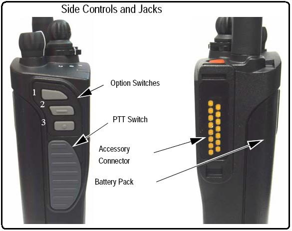
Once Control Top and Keypad Test Mode is selected from the menu, all icons are displayed and the LED lights red. Upon release of the emergency button, the radio is in "Control Top and Keypad Test Mode". In this mode, all of the buttons, switches, and knobs on the radio can be tested to determine if they are operating correctly. Performing any event with the radio results in a tone as well as a display of what action took place. A summary of the displays is shown in Table 4. If the radio is in "Control Top and Keypad Test Mode" but no action is taking place, the message "CH Test" continues to display.
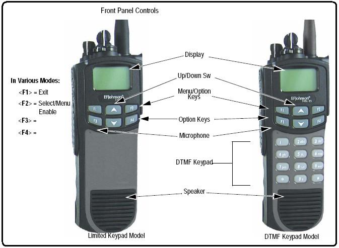
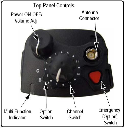
Table 4 - Control Top and Keypad Test Mode Display Messages for the 5100
| Action | Display |
|---|---|
| Emergency button pressed/released | Emer: 1/Emer: 0 |
| Channel selector switch moved | Chan: x, where x is the current position of the switch |
| Toggle switch moved | Toggle: x, where xis the current position of the switch |
| Volume knob turned | Vol: x, where x is the current position of the knob from 0 - 255 (this will vary at the boundaries) |
| Side button 1 pressed/released | SB1: 1/SB1: 0 |
| Side button 2 pressed/released | SB2: 1/SB2: 0 |
| Side button 3 pressed/released | SB3: 1/SB3: 0 |
| PTT button pressed/released | PTT: 1/PTT: 0 |
| F1 button pressed/released | F1: 1/F1: 0 |
| F2 button pressed/released | F2: 1/F2: 0 |
| F3 button pressed/released | F3: 1/F3: 0 |
| F4 button pressed/released | F4: 1/F4: 0 |
| Up button pressed/released | Up: 1/Up: 0 |
| Down button pressed/released | Down: 1/Down: 0 |
| "1" button pressed/released | Btn 1: 1/Btn 1: 0 |
| "2" button pressed/released | Btn 2: 1/Btn 2: 0 |
| "3" button pressed/released | Btn 3: 1/Btn 3: 0 |
| "4" button pressed/released | Btn 4: 1/Btn 4: 0 |
| "5" button pressed/released | Btn 5: 1/Btn 5: 0 |
| "6" button pressed/released | Btn 6: 1/Btn 6: 0 |
| "7" button pressed/released | Btn 7: 1/Btn 7: 0 |
| "8" button pressed/released | Btn 8: 1/Btn 8: 0 |
| "9" button pressed/released | Btn 9: 1/Btn 9: 0 |
| "0" button pressed/released | Btn 0: 1/Btn 0: 0 |
| "*" button pressed/released | Btn *: 1/Btn *: 0 |
| "#" button pressed/released | Btn #: 1/Btn #: 0 |
Cycle the radio's power to exit any test mode and return to normal operation.
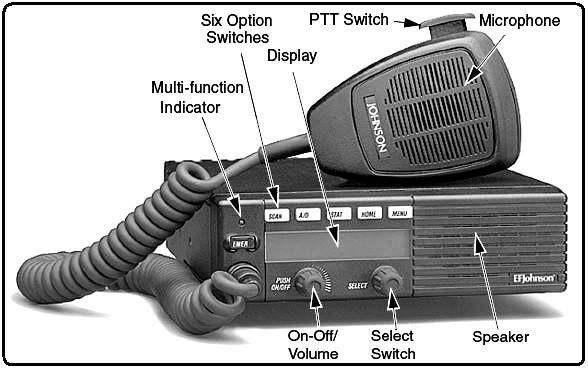
5300 - Control Head Test Mode:
Once Control Head Test Mode is selected from the menu, all of the buttons and knobs can be tested to determine if they are operating correctly. Performing any event with the radio results in a display of what action took place. A summary of the displays is shown in Table 5. When no action is taking place, the message "CH Test" continues to display.
Table 5 - Control Head Test Mode Display Messages for the 5300
| Action | Display |
|---|---|
| "EMER" button pressed/released | F1 1/F1 0 |
| First button pressed/released | F2 1/F2 0 |
| Second button pressed/released | F3 1/F3 0 |
| Third button pressed/released | F4 1/F4 0 |
| Fourth button pressed/released | F5 1/F5 0 |
| Fifth button pressed/released | F6 1/F6 0 |
| "Select" knob pressed | SEL 0 |
| "Select" knob rotated clockwise | ROT CLK |
| "Select" knob rotated counterclockwise | ROT CNTR |
| "Volume" knob rotated | VOL x, where x is the current position of the knob from 1 - 100 |
Cycle the radio's power to exit any test mode and return to normal operation.
Contact Information:
The compiler can be contacted at: his-callsign [ at ] comcast [ dot ] net.
Back to the top of the page
Up one level
Back to Home
This page originally posted on 03-Jul-2012
This web page, this web site, the information presented in and on its pages and in these modifications and conversions is © Copyrighted 1995 and (date of last update) by Kevin Custer W3KKC and multiple originating authors. All Rights Reserved, including that of paper and web publication elsewhere.