E.F. Johnson CR1010
Alignment Procedures
by Clay Brown KI4ONH
Note: All diagrams in this writeup are clickable into larger sizes.
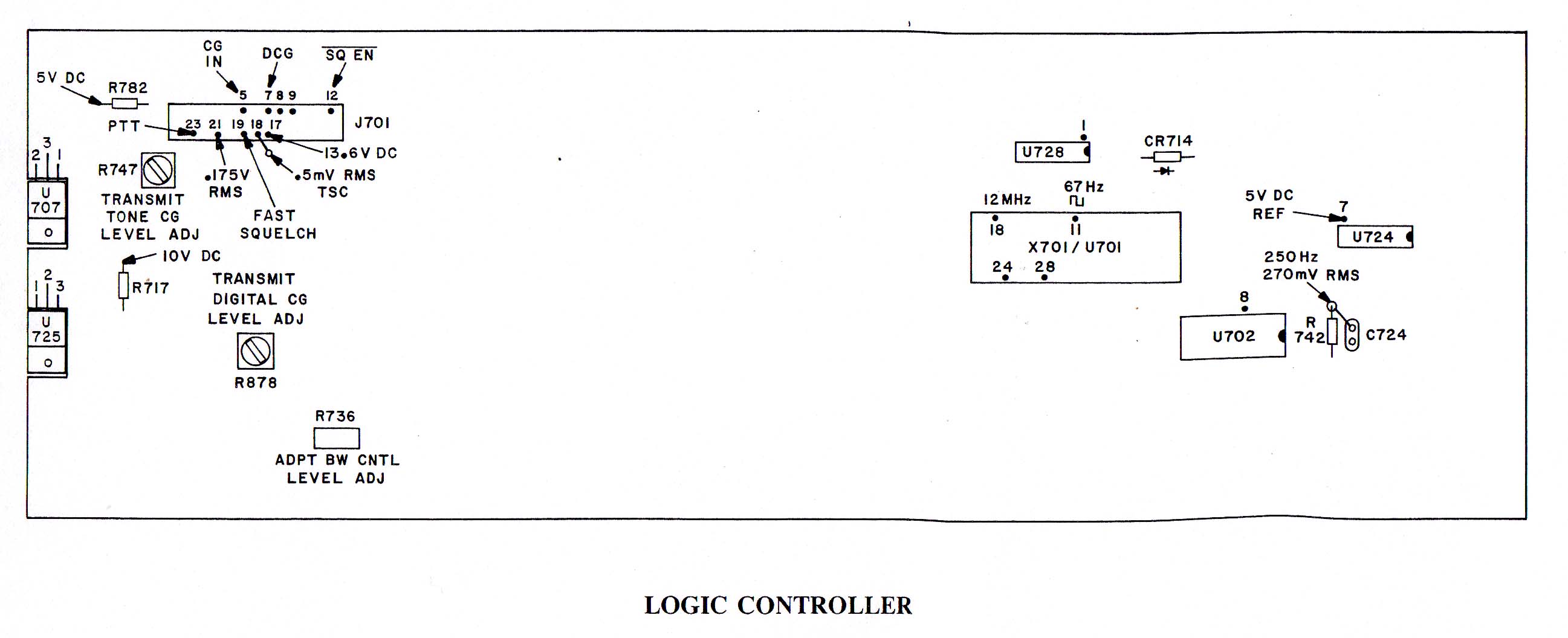
These alignment procedures can be performed with the Receiver, Transmitter and Logic drawers in the repeater or separately on the service bench. Before making any adjustments verify correct DC Voltage (13.8v) on J160 Pin 7 on the Transmitter drawer, J560, Pin 7 on the Receiver drawer and J780, Pin 17 on the Logic drawer.
Receiver Alignment:
FIRST SECOND AND THIRD TRIPLER ADJUSTMENT
1 Install TXCO
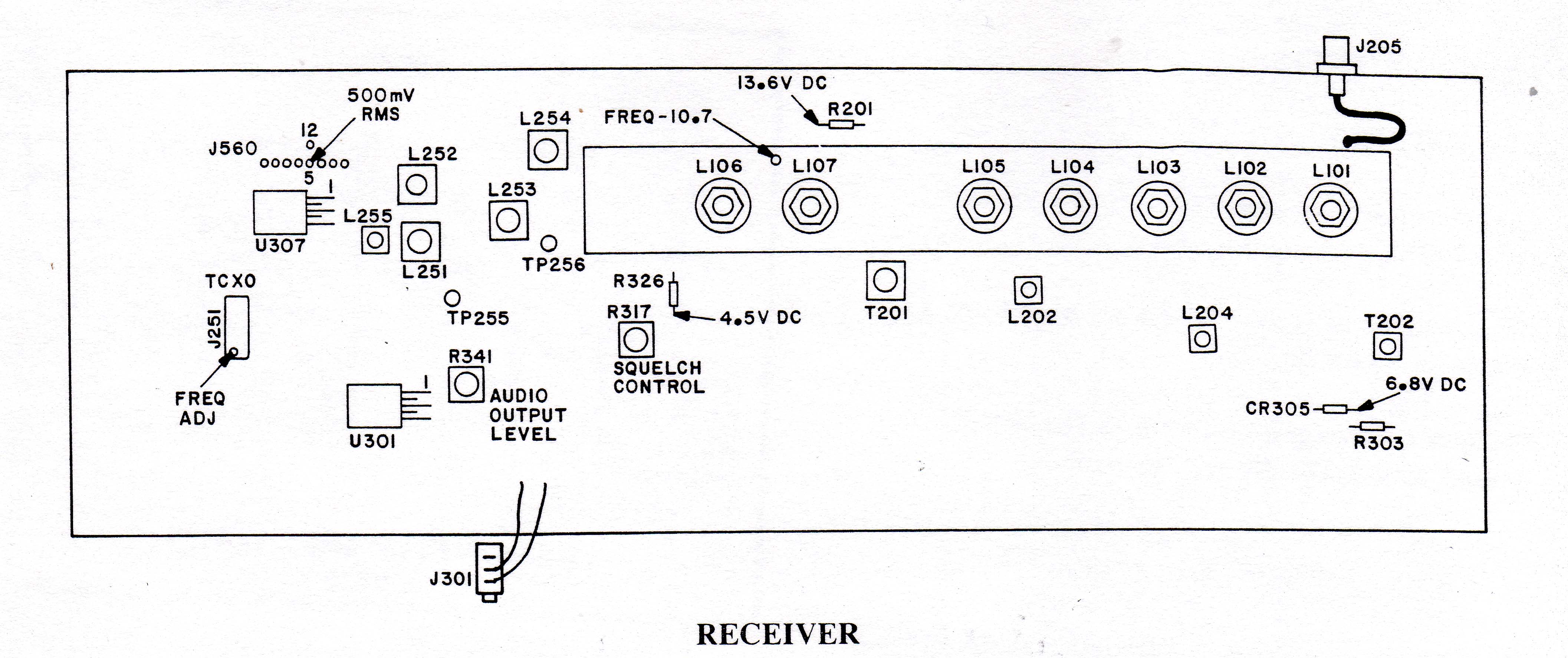
2 Connect DC Voltmeter to TP255. Tune L251 and L252 for maximum DC Voltage. Alternate adjusting until maximum voltage is achieved.
3 Connect DC voltmeter to TP256. Tune L253 and L254 for maximum DC Voltage. Alternate adjusting until maximum voltage is achieved.
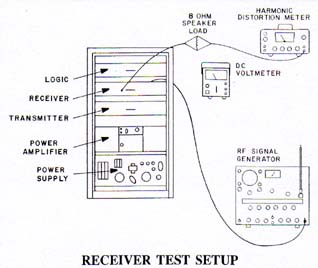
IF AND FRONT END ALIGNMENT
1 Turn on the local volume control and using local speaker as the monitor set R317 Squelch Control to Threshold.
2 Connect an RF Generator to J201 (Rear antenna input) and set to on channel frequency modulated with 1 kHz at 3 kHz deviation. Connect a SIN ADDER to audio test jack in the front of the cabinet (J301). Raise the Level sufficiently to "Force" a signal through the front end. Tune L107-L107 and T201 in sequence for the best 12 dB SINAD while continually decreasing the RF levels as succeeding stages are tuned.
3 Using a appropriate RF frequency measuring instrument, measure and set the correct frequency of the first injection chain by adjusting the tuning capacitor located at the top of the TCXO. (lightly couple with a probe through the hole in the top of L107 helical cavity. The frequency measured will be 10.7 MHz below the on-channel frequency.)
4 Raise the generator RF level to 60 dB above level of 12 dB SINAD sensitivity. Measure distortion of audio output at J301 and Tune L202, L204, and T202 for minimum audio Distortion. Audio distortion should be less than 1.5%
5 Set audio output level to 0.5V RMS at J560, Pins 5 and 12 by adjusting R341
6 Readjust Squelch control (step 1 above)
7 Decrease RF generator output to the 12 dB SINAD sensitivity and carefully readjust L101 through L107 for best 12 dB SINAD sensitivity. Receiver sensitivity will typically be 1 dB better at the high end of the frequency range than at the low end.
Transmitter Alignment
Exciter
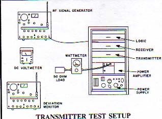
1 Disconnect coax from PA input port J201 and connect to a wattmeter with a 25 Watt element terminated to a dummy load.
2 Install TCXO.
3 Connect DC voltmeter to J301
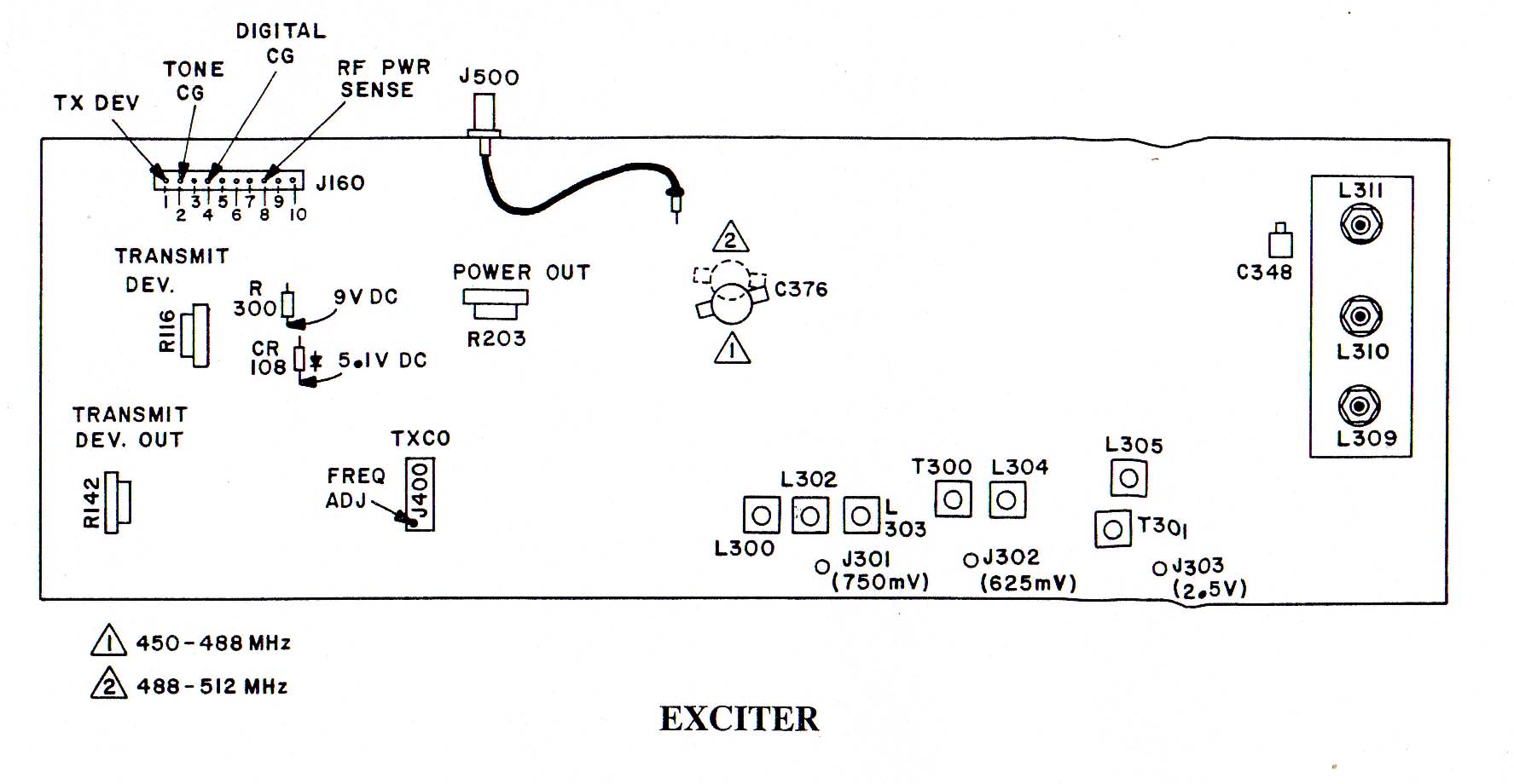
4 key Transmitter and tune L300, L302, and L303 for maximum DC Voltage (typically 750mv)
5 Connect DC Voltmeter to J302
6 Tune T300 and L304 for maximum voltage (typically 625 mv)
7 Connect a DC Voltmeter to J303
8 Tune T301 and L305 for maximum voltage (typically 2.5 V)
9 preset helical screws to maximum depth into casting
10 Monitor helical output filter at C348 with a RF Voltmeter. Back each helical screw out of the casting one turn at a time, in sequence until power is obtained
11 Tune helicals for maximum power out
12 tune C376 form maximum power out
13 Retune T301 and L305 for maximum power out (Typically 18 Watts)
14 Reconnect coax PA input port J201
Power Amp
1 Connect a Wattmeter (250 Watts) and a dummy load to the power amplifier output, J202
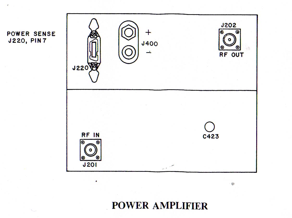
2 Key transmitter and adjust R203 in the exciter for 100-110W at the PA output port. (Exciter output is typically 5W - 18W)
3 Tune C423 in the PA for Maximum power out at output port J202. Readjust R203 if needed
4 Monitor the output Frequency, set the frequency on channel by adjusting the tuning capacitor in the TCXO
Contact:
Clay Brown can be contacted at KI4ONH /at/ wc4m /dot/ net
Downloadable Documentation:
CR1010 Service Manual 8.6 MB PDF file
CR1010 CWID Prom Programming 123 kB PDF file