Back to Home
By Gary L. Peterson, NZ5V
Last modified: March 28, 2004

|
Up one level Back to Home |
Conversion of the GE RANGR LowBand Radio to Amateur Use By Gary L. Peterson, NZ5V Last modified: March 28, 2004 |
|
Table of Contents (click to jump to that section)
The purpose of this document is to provide accurate modification instructions and helpful information as a guide to modifying the various models of GE RANGR Low Band radios to full operation on the entire amateur 6 meter band.
We will provide two levels of instructions, one for those with limited test equipment and two, procedures for those with service monitors or other similar equipment.
These modifications cover all upper segment low band model GE RANGRs made. The RANGR was produced in two versions, the RANGR and RANGR "89".
Referring to the GE tag on the back end of the radio, best radios to get for 6 meter use are:
Next best two are:
A noise blanker is not a requirement on a radio, but on 6 meters it is a very desirable option. Get a P7 or P8 radio if you can.
The latter radios (with the 051 in the part #) require about an extra 30 minutes to modify. NO additional parts are required to modify the radios.
OPTIONAL TOOLS
The modifications are in two areas, the VCO board and on the RANGR 89 (radios with 051P in the part number) the PA board.
RANGR 050s may also require part of the RANGR 89 PA board modification if they do not produce full rated power out at 54 MHz.
The VCO mod consists of removal of the VCO board from the radio, removal of both of the large black potted TX and RX coils, removal of one-half turn from each, and reassembly.
The 050 RANGR typically will operate at full rated power without any modification. However, if you do have an 050 RANGR whose output power falls as you move from 50 to 54 MHz, you may need to perform the Low Pass Filter modification portion of the RANGR 89 051 modification.
Sometimes the flat capacitors on the PA board will explode after conversion, when you key down and transmit for a while above 52 MHz. The component was just old and must be replaced.
POWER AMPLIFIER WARNING
When testing the PA for the first time, be sure to reduce the power output to about half before transmitting. Then, check the components in the PA final for excessive heating.
After conversion the receiver typically will need a slight re-adjustment to provide best performance at 54 MHz. A signal source is necessary for this step. Another 6m radio will work in a pinch.
The squelch may barely close at 54 MHz. A simple adjustment usually cures this problem.
If it does not, you will need at least a service monitor/calibrated signal generator and perhaps a Distortion Analyzer with a 4 ohm 15 watt dummy load in order to perform a full receiver alignment.
First, get a 12vdc power source of at least 20 amps, and your cable, head, microphone and speaker. Plug everything up and power up the radio.
If you have the ability to program the radio, enter a test personality set from 39 to 54 MHz in 1 MHz increments.
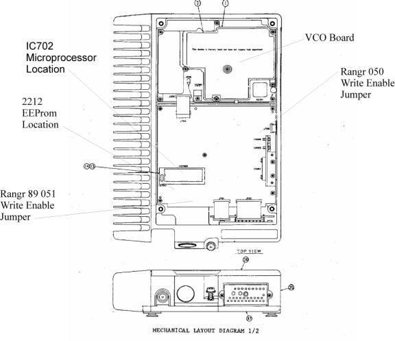
The write enable jumper is located on the system control board. It's the board nearest to the cable and antenna connection.
RANGR 050 - J 706 Pins 2-3 enable, 1-2 for s500/550/600 heads on the RANGR
J 707 Pins 2-3 enable, 1-2 for s500/550/600 heads on the RANGR 89.
Click on the image for a larger one
RANGR 050 models - check the receiver sensitivity and transmit power. Typically the radio will "unlock" around 52 MHz. Radio may receive higher than transmit.
RANGR 051 models - check the receiver sensitivity and transmit power. Typically the radio will "unlock" around 50-51 MHz. Radio may receive higher than transmit.
Now is a good time to turn the transmitter power down, to prevent the PA from being burned up.
YOU ABSOLUTELTY MUST DO THIS ON THE 051 RANGR 89 Radios.
It's a good idea to turn the 050 radio PA down too. Sometimes they can put out more than 110watts and it's hard on the PA Final transistors.
Turn the radio over, remove the back cover and locate the two adjustment pots in the middle of the long PA board. The pot labeled RV1 adjusts the output power. Turn it counter-clockwise until the wattmeter reads 25 watts output.
If you can't program the radio and are sending the PROM to someone later, just check the radio as best you can to make sure it's operating properly before starting the modifications.
Pull the top cover of the radio off, and position the radio with the cable and antenna connections closest to you. The radio is divided into two sections, the top section is the VCO board, the bottom section is the system control board.
Remove the VCO board from the radio.
You will need to detach the ribbon cable, the small coax, and remove the square silver colored oscillator box. The oscillator just unplugs from the board.
Use the torx driver to remove the VCO board from the radio housing.
Turn the VCO board over and remove the screws on the back of the VCO board. They hold the aluminum cover on the VCO board.
CAUTION: Handle the VCO board CAREFULLY. There are surface mounted parts on the back of this board. They are easily damaged.
Locate the two large round black potted coils on the top side of the board. Notice that they are DIFFERENT. The radio won't work if you swap them.
REMOVE THE VCO COILS ONE AT A TIME, MODIFY THEM AND THEN REPLACE THEM BEFORE REMOVING THE OTHER ONE.
Use a large high heat soldering iron. Remove the VCO coil from the board, being careful not to damage the surface mounted parts on the back side of the board.
Using a pair of dikes, carefully cut the black potting away from the outer edge beginning at the right side of the coil leg, and go counterclockwise for one-half turn, clearing away the material so that you can remove one-half turn from the coil, and then replace it into the VCO board.
Cut the excess wire from the coil and locate the new end of the coil so that it will press fit back into the VCO board. Solder it back.
Repeat the process with the other VCO coil.
Use a screwdriver or small knife to clear the holes out in the aluminum top cover of the VCO board. You will need to access the adjustments and test point during later steps in the conversion process.
Replace the VCO board aluminum cover, then replace the board in the radio, being sure to re-connect the coax, ribbon cable, and oscillator assembly back into the VCO board.
Ranger 050 models - go to the VCO Adjustment Step from here.
See this link for helpful info until I get the pictures done for this document:
http://www.packetradio.com/pdfzips/rngr6mod.pdf (local copy)
Locate CV202, your TX VCO adjustment point, Test Point TP201, and the VCO Unlock LED CD710.
You may need a second person for this step. While holding the meter probe on TP201, key the transmitter and adjust CV202 for a reading of 7.5 volts at 54 MHz. If you don't have the radio programmed, wait until you do and then use the highest TX frequency channel that you have programmed.
The TP201 should vary no lower than 3.5vdc on the lowest and no higher than 7.5vdc and highest TX channel you will be using.
LED CD710 next to the large silver box on the system board should NOT be lit on any channel when you key the transmitter after you have readjusted the TX VCO.
NOTE: The LED CD710 may light back up when you un-key the transmitter because the RX VCO is not adjusted properly.
Locate CV201, your TX VCO adjustment point, Test Point TP201, and the VCO Unlock LED CD710.
While holding the meter probe on TP201, adjust CV201 for a reading of 7.0 volts at 54 MHz. If you don't have the radio programmed, wait until you do and then use the highest TX frequency channel that you have programmed.
The TP201 should vary no lower than 3.5vdc on the lowest and no higher than 7.5vdc and highest TX channel you will be using.
LED CD710 next to the large silver box on the system board should NOT be lit on any channel after this adjustment is complete.
Adjust the tuning coil xxxx while injecting an on frequency signal of low level on the highest frequency channel you will be using for maximum quieting.
Then adjust RVxxx counter-clockwise all the way.
If you have a service monitor with a SINAD or Distortion Analyzer instead follow the instructions in the GE LBI for receiver alignment and squelch adjustment.
Remove the PA board from the radio. It is located on the other side of the radio housing from the VCO board.
NOTE: One transistor on the PA board has an insulating washer on the mounting screw. Be Sure to replace this insulated screw in the correct location.
Locate the largest ferrite transformer, next to the final PA transistors. There is a red silver mica capacitor across the input of the transformer. It is a 330pf. REMOVE IT. Just clip it off the transformer.
Unsolder the braid tab from the SO-239 antenna connector. Remove the screws from the back of the PA board that hold the aluminum cover and the SO-239 connector.
A series of coils that were under the aluminum cover are the final low pass filter for the radio. It will not pass 54 MHz without excessive heating of the final transistors. CAREFULLY stretch each coil out a moderate amount, except for the one nearest the PA transistors, or furthest from the antenna connection. Only stretch it out a little.
If you have a service monitor with a spectrum analyzer and tracking generator or a sweep generator and detector, check the filter for roll-off below 54 MHz.
Replace the aluminum cover, making sure that the stretched coils all fit under the cover properly.
BE SURE TO RESOLDER THE SO-239 ANTENNA CONNECTION BEFORE REPLACING THE PA BOARD BACK INTO THE RADIO CHASSIS.
BE SURE TO REPLACE THE SCREW WITH THE PLASTIC INSULATOR BACK ON THE TRANSISTOR AT THE FAR END OF THE PA BOARD, NOT THE TRANSISTOR LOCATED ON THE LONG SIDE OF THE PA BOARD.
Test the power output by keying the transmitter on the highest transmit channel or on 54 MHz. Into the wattmeter and dummy load.
If the power level is the same or greater than before the modifications, slowly adjust the transmitter power up to 90-100watts. Un-key and check for hot parts in the final area. Particularly check the coils of wire on the largest of the ferrite transformers, the flat metal capacitors, and the PA final transistors. If you have an IR thermometer, look for any area that is above 155 degrees F after key down. Slowly increase the time you key down and if you can exceed 60 seconds without a rise above 160 degrees, you are done. If you don't have a thermometer, touch the parts (with the transmitter OFF) and anything that feels HOT is too hot. Warm is ok. HOT is not.
If you have hot parts, check the power out on the lowest and highest transmit frequencies. You should have a higher power out on the lower frequency.
If you do have more power out as you go up in frequency, remove the PA board and expand the LP Filter coil closest to the PA transistors a little and do the same for the other coils and then reassemble the PA into the radio's casing.
If you don't have more power out as you go up in frequency, remove the PA board and compress the LP Filter coil closest to the PA transistors a little then reassemble the PA into the radio's casing.
The first coil in the LP filter has the greatest effect on the heating problem.
When you have 90-100 watts output on the highest transmit frequency you are done.
Back to top of the page
Up one level
Back to Home
This page originally posted on 06-Aug-2004
Article contents Copyright © 2004 by
Hand-coded HTML © Copyright 2006 and date of last update by repeater-builder.com
This web page, this web site, the information presented in and on its pages and in these modifications and conversions is © Copyrighted 1995 and (date of last update) by Kevin Custer W3KKC and multiple originating authors. All Rights Reserved, including that of paper and web publication elsewhere.