Step
by Step procedure for duplexing the Custom MVP®
By Kevin Custer W3KKC
Build
a Repeater from a GE Custom MVP
HF,
VHF, or UHF units can be converted to repeater.
Read through this entire procedure before beginning.
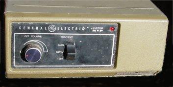
General: The
G.E. Custom MVP is a crystal controlled, under dash mounted, commercial
two-way transceiver closely related to the MASTR II and MASTR Executive
II series. Compared to the other two models, the MVP is the smallest
of the 3 measuring only 3.5" H x 8.4" W x 11" D, including all projections
& heatsink on the 35 watt model. The MVP typically comes in a
5, 20 or 35 watt model. Although this article shows pictures
of the UHF model, the duplexing instructions also apply to the HF and VHF
models as well. The 66 suffix model is spec'd for 150.8-174 MHz but
will tune down to the 2 meter ham band without modification and have reasonable
sensitivity. The 88 suffix is spec'd for 450-470 MHz but will
tune down into the UHF ham band without modification and have reasonable
sensitivity.
This conversion was written primarily for the installation of the
NHRC-4/MVP controller
custom made for the GE MVP.
The GE Custom MVP makes one of the nicest portable, compact, rugged,
and cleanest repeater projects you will see.
Forward:
This modification is not for the faint-hearted. Although the MVP®
mobile radio system is one of the easiest of the commercial mobile radios
to convert to a repeater, you should be sure you are very comfortable with
the operation of the radio before you attempt this modification.
A thorough understanding of the way the MVP® radio and control system
work is absolutely essential for the success of this conversion.
A manual is not necessary, but is desired for comprehending the conversion
and tune-up; that being said, support for your MVP conversion may be available
from a few resources.
These resources are listed below:
GE MASTR II/MVP Email List.
Repeater Elmers.
Email
support from the author of this article.
Disclaimer:
The Author nor NHRC assumes any liability for any damages to your Custom
MVP radio set or any associated equipment from your inability to perform
these modifications. If you have any doubt about your ability to
correctly modify your radio or to install the repeater controller seek
professional assistance. Damage to your MVP
or NHRC-4/MVP controller due to improper radio modification, improper installation,
or improper hookup of the controller is not covered under any warranty.
Choosing a radio to convert:
These links will help you determine what you have or what you are about
to buy:
MVP Radio Combination
Numbers (Nomenclature) from Hall Electronics
MVP Transmitter
ID Numbers from Hall Electronics
Concept:
Some of the information in this article was gleaned from the NHRC-4/MVP
manual as there are instructions contained within it to help convert the
MVP to a repeater. The information being used in this article from
NHRC LLC is being done so with written consent.
The following instructions are provided to help convert a General Electric
Custom MVP mobile 2-way radio to a repeater station. Modification
of the SAS Board and Rear Panel, for addition of a second antenna port,
allows the radio to operate full duplex. This modification is intended
for those who are using a newer type controller which provides a means
of muting and de-emphasizing the audio of the receiver. NHRC controllers
provide both functions; therefore an additional interface board is unnecessary.
This modification was written primarily for the NHRC-4/MVP controller,
however, the instructions can be followed to attach any controller.
The /MVP suffix refers to a type of controller which bolts into the MVP,
in the spot formerly occupied by the original Channel Guard (CTCSS)
board. The /MVP controller allows for a clean, slim line repeater
to be fashioned, with all support being contained within the chassis.
Before you begin, a word of caution:
The first thing to do is ensure your MVP is tuned up and working.
If the unit is being converted to the ham band, make sure the radio works
properly in its original band and split before any modifications are made.
This will allow you to repair any problems first, which could result in
really getting lost. Afterwards, retune the radio to the ham band
before any duplex modifications are made so you will know what to expect
as far as transmitter output power and receiver sensitivity are concerned.
The use of the power cable and microphone are necessary to insure the radio
is operating properly. Borrow a cable assembly from a friend or visit
the local 2-Way shop and see if they will test the radio set for you.
Alternately, use the information below to power the radio and use the mike
connector image to ground pin 3 as to key the radio so you can test the
transmitter. In actual repeater operation, a local microphone is
not needed, and these instructions don't allow for the connection of one.
Some of the information in this article is from hyperlinked pages removed
from this site. You may need to use your browsers "Back" button to
return to this article.
Powering:
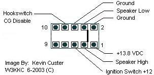
Rear Power and Speaker Connector
Pinout Image.
Mike Connector:
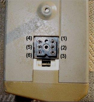
Mike Connector Pinout Image.
Procedure:
-
If you haven't already done so; test your radio on the frequency it is
currently tuned, then, re-crystal your channel ICOM's (crystal oscillator
module, or channel element) to your repeater frequencies. This is
done by either sending the ICOM's to a reputable crystal house or getting
replacement crystals and installing them into the elements yourself.
Retune the radio to the new frequencies by using a 'Test Set' or analog
(needle
type) VOM and the
tuning instructions here.
-
Start the conversion by disassembling the radio set, which is done by removing
the outer cover which is held on with a nut on the back of the radio set.
Remember how you take the radio apart so you can get it back together as
it was. Next, remove the four screws that hold the front panel in
place. This allows you to get to the SAS and (if installed) Channel
Guard board.
-
If installed, remove the Channel Guard (CG) board. This board is
the smaller of the two, located next to the SAS board and can be identified
by its lack of connectors. Unplug or cut off any connections from
the CG board to the SAS board or wherever they may terminate. This
includes all wires that plug in or otherwise get connected. Also,
unplug the CG encoder cable (shielded wire) that runs from the CG board
to the exciter. You will likely have to cut the rope loom that tailors
the cabling. You may want unspring and keep the terminals and wires
from connectors for re-use as they come in handy when interfacing the needed
repeater signals to the radio after all of the duplex modifications have
been performed.
-
Do the duplex modifications to the SAS
board as described on this linked page. This step is necessary
to allow for simultaneous transmitter and receiver operation. This
is done by defeating and strapping the receiver oscillator always on and
disabling the receiver muting circuitry.
-
After doing the SAS Board modifications go back over your work then replace
the SAS Board back onto the front of the chassis. Use caution when
replacing the board so the mounting tabs of the audio IC and the transistor
insulators get seated back into their proper position.
-
Now re-connect the two plastic connectors back onto the SAS board.
There will be 2 individual wires bundled along with the smaller connector
that need to be plugged into the SAS board. One of these wires may
have been connected to the CG board if originally installed, however it
will now be plugged into the SAS board. This one (may be Gray or
Blue in color) is now plugged onto the single vertical pin near J905 pin
7 as shown in this SAS connector detail image.
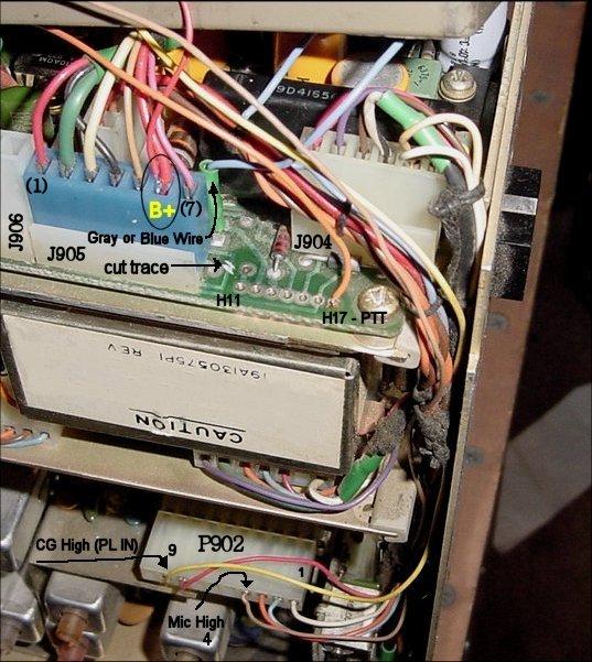
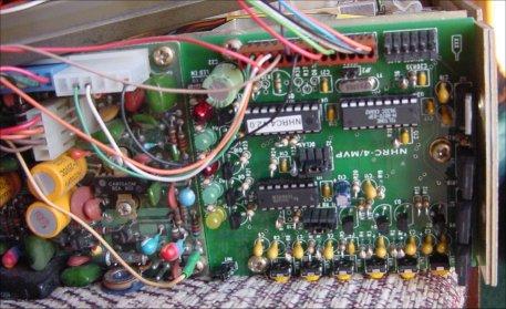
The other wire (usually yellowish in color)
is plugged back onto its original location; the single vertical pin at
the opposite corner of the board as
shown in the bottom of this picture with the NHRC controller installed.
-
If your radio has an orange lead from the front panel Squelch Switch, cut
off or tape this lead as it is no longer required.
-
Re-test your radio for proper operation. It should receive and transmit
simultaneously. If it doesn't, now is the time to fix anything that
may have gone wrong with the modification before you proceed.
-
Add the receiver antenna connection
as outlined on the linked page.
-
Deal with the T/R Relay (or not?)
-
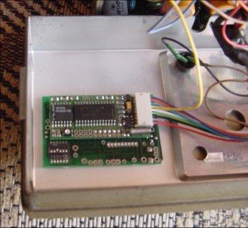
Install the NHRC controller and CTCSS decoder as directed in the controller
manual. We use the Com-Spec TS-64DS board for the CTCSS, PL, CG or
whatever you want to call it, and stick it to the front panel as shown in
this image.
Make note of the next 2 steps as you have the option to do it that way
NHRC states in their manual, or a different way I suggest.
-
I suggest you connect the controllers B+ power differently than what is
suggested in the NHRC manual. I prefer to power the controller from
13.8 volts instead of 10.0 for technical reasons. I simply supply
the controller with power from the B+ lead (J906 pin 6) on the SAS board
as shown in the connector detail image below.
-
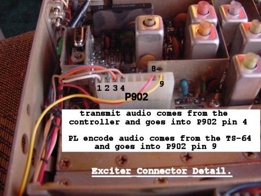
I also suggest you run controller transmit and ctcss audio directly to
connector P902 on the exciter. I remove the original pins and wires
from the connector and re-use the pins on new interconnecting wires. The
exciter connector detail shows the connection of the TX Audio and PL Audio
to P902.
-
Install a PTT Disable Switch. This switch can be easily installed
by inserting the switch in series with the PTT signal from the controller
to the radio set. The front panel is a good place to physically mount
the switch. A momentary push button switch can also be placed and
wired to enable the transmitter for testing (momentary PTT test switch).
We wire the PTT test switch through the PTT disable switch so you cannot
make the transmitter operate at all unless the PTT Disable switch placed
in the Operate position. Connection of the PTT signal from the controller
to the radio terminates at H17. The SAS connector detail image also shows this
location, H17.
-
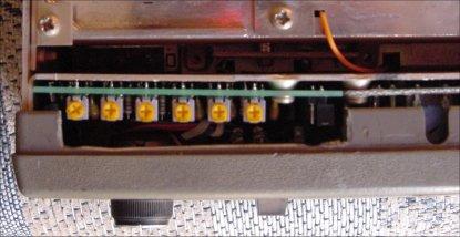
Cut a slot in the top of the front panel to gain access to the control pots
on the NHRC-4/MVP controller as shown in the potentiometer cut-out image.
-
Replace the front panel onto the radio chassis using the 4 screws being
careful not to pinch any wires.
-
Add a length of quality power cable to the radio and terminate it with
the connector(s) of choice that mates with your power source.
-
Set levels and program your controller.
-
Place the cover back onto the radio set.
-
Either terminate the speaker connections (SKR HI and SKR LO) with a local
speaker (jack) or a load resistor so the audio amp doesn't oscillate.
A local speaker is nice to allow you to listen for desense. Refer
to the first link under the "Powering" section for connection to the speaker
terminals.
-
You are done!
This site, its contents, and look & feel are Copyrighted©
2002 Kevin K. Custer W3KKC
Some information provided in cooperation with NHRC LLC.
All Rights Reserved.