Modifying
the MVP SAS Board
for
full duplex operation.
By Kevin Custer W3KKC
Concept:
Modification of the System-Audio-Squelch or "SAS Board" is necessary to
allow a GE MVP Mobile radio operate full duplex to become a repeater.
Modification is accomplished by performing several steps below. a
few high resolution pictures are included in these steps to guide the builder
and help insure the modification is performed correctly. These steps
are not for the inexperienced builder.
Modification Procedure:
-
Remove the SAS board from the radio set. These boards vary slightly
from revision to revision but are fundamentally the same. Remove
the two screws from the Audio IC that secure it to the heatsink.
Be careful as there are small "shake proof" washers under the heads of
the screws. Next, remove the screw that secures the TO-220 transistor.
Be
Careful of the insulators above and below the transistor, they must
be reinstalled later. Now, make a note of the connections you are
about to disconnect. The front panel assembly can be removed and
set aside by unplugging the cabling.
-
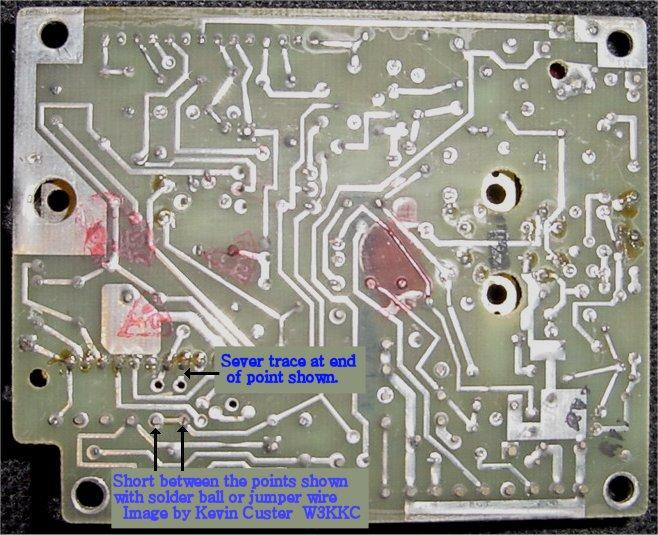
It is necessary to activate the receiver circuits continuously by applying
power to the receive oscillator. This is accomplished by shorting
between J904 pin 1 and 2 on the solder side of the board. I used
a resistor lead clipping to make the jump. This is pictured in the
first image below.
-
Now we need to defeat the oscillator control circuitry. This
step requires cutting a trace on the SAS board so be careful. This
step is accomplished by finding and cutting the PC board trace that connects
J904 pin 2 to the hybrid IC U902 (long narrow black chip) pin 7.
For reference, the pin numbers are molded on the top side of this chip
at each end beyond the stamped on part number. This trace is cut
in the short area between the IC's pin and the plated through hole on the
solder side of the PC board and is pictured in the first image below.
-
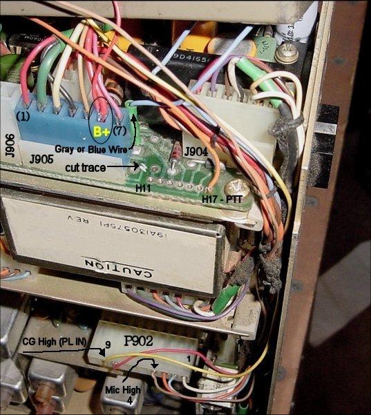
For obvious reasons, it is necessary to disable the receiver muting circuitry.
This is done at by severing a trace that connects to U902 (long black chip)
pin 6, but this time will be cut on the parts side of the board near pin
7 of J905. This step is accomplished by finding and cutting the circuit
trace that is in the form of a large "S". Cut the trace beside H11
as shown below.
-
Proceed onto Step 5 of the main conversion page.
This site, its contents, and look & feel are Copyrighted©
2002 Kevin Custer W3KKC
All Rights Reserved.