Back to Home
Power Supply Capacitors
By Robert W. Meister WA1MIK

|
GE index Back to Home |
Replacing the MLS-II Power Supply Capacitors By Robert W. Meister WA1MIK |
|
Background:
In the months I've been playing with MLS-II radios, every one has had an annoying 100 Hz hum audible in the speaker on received signals. This hum will also prevent detection of a 100.0 Hz Channel Guard tone, if used. It may also reduce the receive sensitivity. One radio also had a very noticeable hiss coming out of the speaker when the radio was transmitting. The front panel display LEDs are multiplexed at exactly this same 100 Hz rate. One power supply regulator is devoted entirely to powering the front panel display in an attempt to keep these current spikes from affecting the rest of the radio. Each of the three power supply regulators has an output filter capacitor, and these go bad. One more capacitor filters the input of these regulators. See the schematic fragment below.
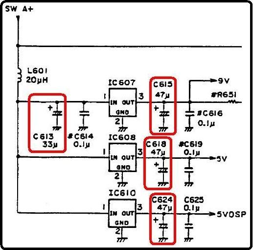
As they're all in the same area, it makes sense that if you're going to take the time to change one, you might as well change all of them for a few more minutes of work. Each of the caps can be bought for about $0.15US from several sources; they're not critical and 85°C temperature range will be fine. Here are the quantities and Mouser part numbers for the Vishay/Sprague radial-lead capacitors I bought:
(1) 33uF, 25V: 75-515D336M025JA6AE3; (3) 47uF, 16V: 75-515D476M016JA6AE3
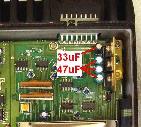
All of these caps are on the system control / synthesizer board located on the top of the radio chassis, next to the microphone connector and the three-terminal regulators. On my radios, the 33uF cap (closest to the microphone connector) was black and about 1/2 inch tall, while the three 47uF caps were blue and about 1/4 inch tall. See the photo below.
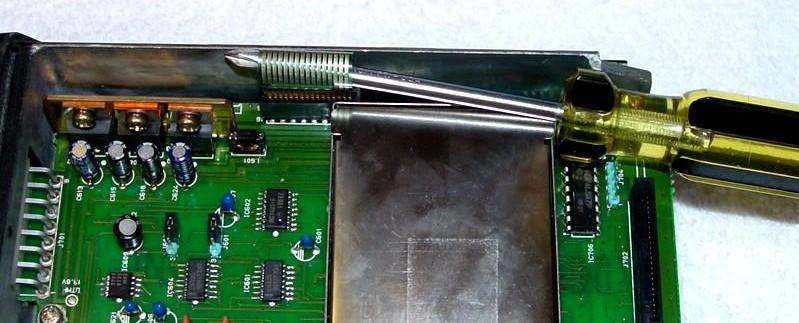
This board must be removed in order to unsolder and replace the four caps. The procedure is fairly easy and you only need a Phillips-head screwdriver. Follow the steps below. The whole job takes less than half an hour.
The MLS (non-PC-programmable) radios can suffer the same problems. All of the power supply regulators and audio output amplifier are on the SysCon2 board that plugs into the SysCon1 board on the top of the radio. It contains ten electrolytic capacitors and it makes sense to replace them all at the same time.
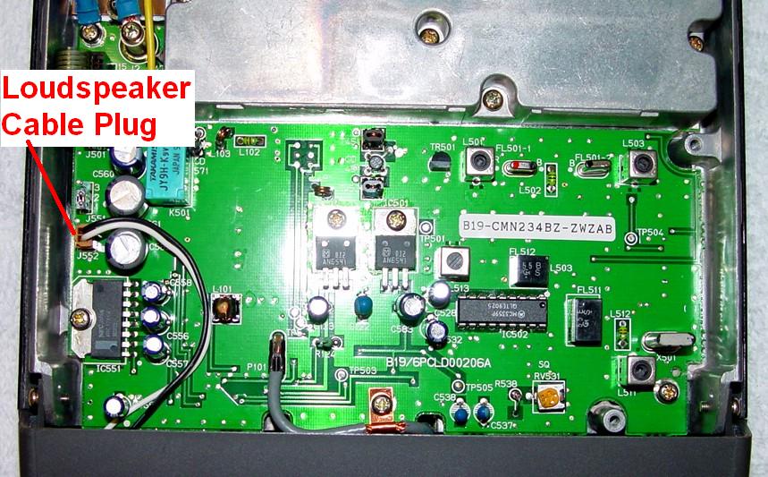
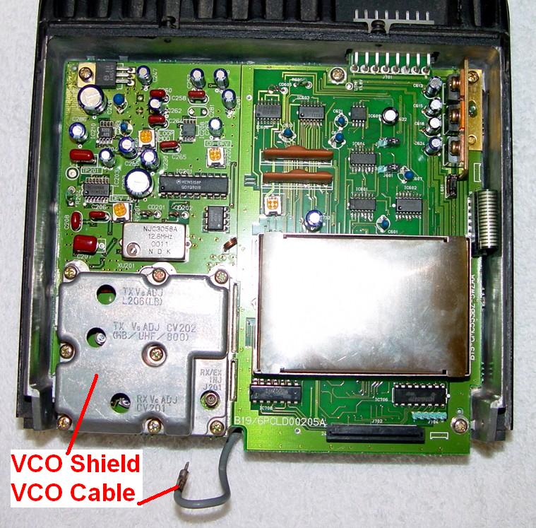
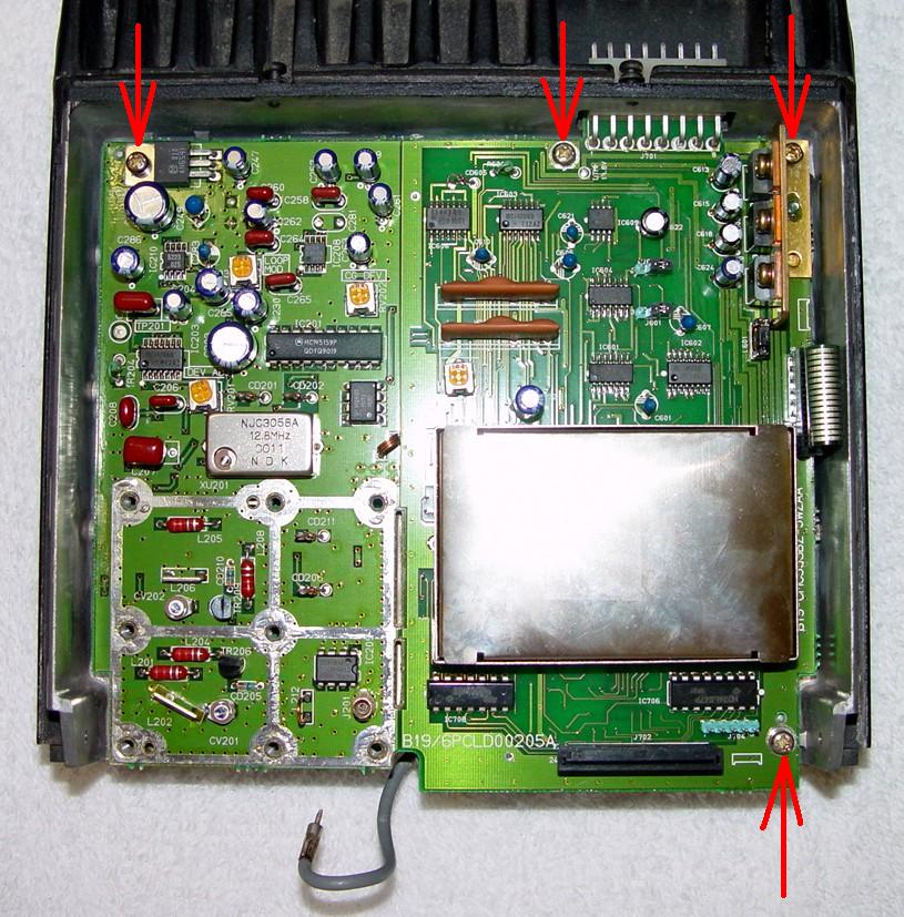
There is one other regulator, for the VCO circuitry, on the left side of the same board. It's visible in the photo below that shows the board's mounting screws. It too has some electrolytic capacitors associated with it that probably should be replaced, namely C247 (1uF, 50F) and C249 (470uF, 16V). I have not investigated these yet, but I have ordered some new ones and will update this article when I have determined if they should be replaced.
Disassembly Procedure:
Replacing the Capacitors:
All four capacitors are located next to the three power supply regulators: the one closest to the microphone connector (rear of the radio) is 33uF 25V; the other three are 47uF 16V (you can use 47uF 25V caps if you want). All of the new caps I bought are black and about 1/2 inch tall and there's plenty of room for them. Follow these steps for each cap; do the 33uF part first as there's only one of them.
Clean the board with alcohol or some other flux solvent.
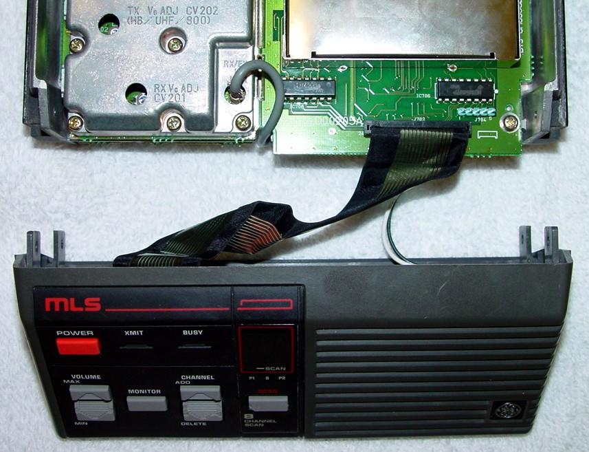
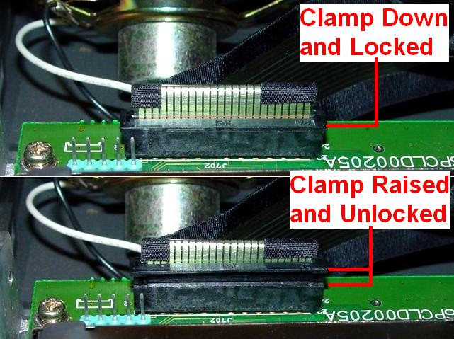
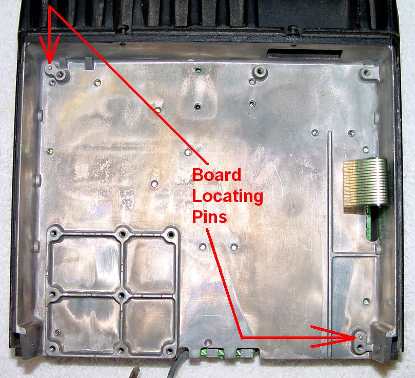
Reverse the disassembly procedure to reassemble the radio. When reinstalling the control board, notice the two locating pins in the chassis, shown in the photo below. Once the board engages these pins, all the screw holes will line up. You can install the screws and tighten them in any order.
Contact Information:
The author can be contacted at: his-callsign [ at ] comcast [ dot ] net.
Back to the top of the page
Up one level (GE index)
Back to Home
This page originally posted on Sunday January 30, 2011.
Photographs, article text, and hand-coded HTML © Copyright 2011 by Robert W. Meister WA1MIK. All photographs were taken by the author.
This web page, this web site, the information presented in and on its pages and in these modifications and conversions is © Copyrighted 1995 and (date of last update) by Kevin Custer W3KKC and multiple originating authors. All Rights Reserved, including that of paper and web publication elsewhere.