Back to Home
Accessory Connector Issue
By Robert W. Meister WA1MIK

|
GE index Back to Home |
GE MLS Radio Accessory Connector Issue By Robert W. Meister WA1MIK |
|
The Problem:
The GE MLS and MLS-II mobile radios have an eight-pin Molex 0.156-inch (KK-series) right-angle male connector sticking through the PA heat sink along the rear of the chassis. The pins are exposed, and any metal object could fall onto these pins and short them out. This isn't a problem once an accessory, such as a microphone or programming cable, is plugged in.
Most, if not all, of the accessory connectors, have a latching mechanism to make removal a bit more difficult. This makes sense in a mobile environment where vehicle vibration is likely. However, the connectors aren't that big and there's very little plastic exposed where you can grab onto it to remove the connector easily. There's no strain relief either, so people tend to pull on the wires a bit as the connector is wiggled off.
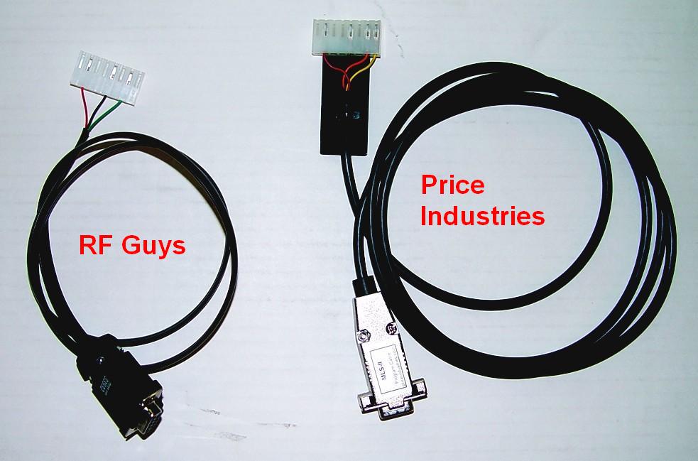
The Price Industries programming cable has a very nice and useful handle pop-riveted to the Molex connector. This makes removal and insertion a breeze, and also offers plenty of strain relief for the cable. But this is something they added to the connector body; as far as I can tell, Molex doesn't offer any handle for this product. See the photo below.
Unfortunately, there is at least 1/4 inch of space on each side of the accessory connector between the pins on the end and the heat sink fins. Also, all eight pins are used; there is no keyway to prevent inserting the mating connector the wrong way. As I found out one day, it's very easy to insert an accessory cable offset by one pin either way, with possibly disastrous results.
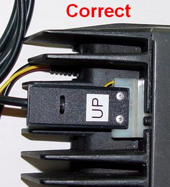
This photo shows the programming cable inserted correctly.
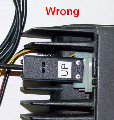
This photo show the programming cable inserted incorrectly, with pin 8 not connected.
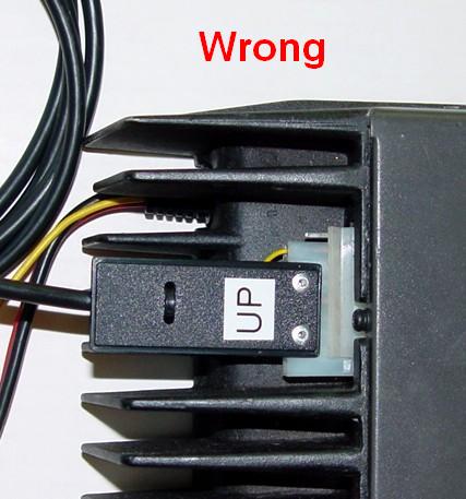
Now, to be fair, if you're staring at the back of the radio when you insert the accessory connector, it should be difficult to insert it incorrectly. In my case the front of the radio was facing me and I just reached over the top and inserted the programming cable without paying as much attention to it as I should have. It got plugged in without mating with pin 1, the one furthest from the edge of the radio (the lowest pin in the photo below).
Pin 8 has switched (and unfused) A+ (13.8VDC) on it. The programming adapter uses this voltage to power the interface IC. Unfortunately, with the cable inserted in this manner, it applied A+ to the TXData line going to that interface IC, instantly destroying it. Of course, all the other programming lines were shifted as well, but the damage was limited to the programming adapter. Because of the excess voltage, both the TXD and RXD circuits stopped working.
I managed to repair the programming adapter by rewiring it to utilize the second set of RS232 transceivers present in the IC. Eventually I unwired my modification and replaced the IC.
The Solution:
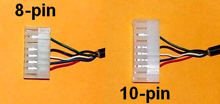
I decided there had to be a better way to protect this from ever happening again, and the solution is to go with a 10-pin Molex connector with polarizing pegs in the outer two pins. This leaves the inner eight pins available but prevents the connector from being plugged in offset by any amount. Besides replacing the connector on the programming cable, I also decided to replace the ones on all the microphone cables I had for these radios.
I only purchased the Molex female connector body and two polarizing pegs for each accessory or cable. I inserted the pegs into the two end positions of the connector body then I transplanted the existing wiring one pin at a time between the original eight-pin body and the new 10-pin body. The contacts are very easy to extract; just depress the little metal locking tab in the cutout along the bottom edge of the connector with a small screwdriver and pull the wire and contact out of the connector body. While the contact is out, use a small knife to gently raise the metal locking tab just a bit so it locks in better. Here are the Mouser and Digi-Key part numbers for the parts I bought:
| Mouser P/N | Digi-Key P/N | Part Description |
|---|---|---|
| 538-09-50-3101 | WM2108-ND | 10-pin Molex 0.156 female connector body |
| 538-15-04-0220 | WM2403-ND | Molex polarizing peg, TWO per connector |
The connector body costs about $0.60 and the keyway pegs about $0.15 each. Here's a photo of a microphone cable showing the original 8-pin connector and the new 10-pin connector with the polarizing pegs in the two outer positions:
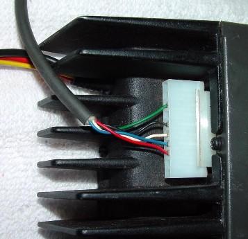
I found that the polarizing pegs prevented the new connector from fully seating into the radio. It does lock into place but the keyway pins extend in front of the connector body and touch the heat sink casting. I could file them down just a bit or glue them in place and file them down flush with the connector body. I don't think they're really necessary because the 10-pin connector body uses almost all the available space in the cutout in the casting so you can't plug it in wrong. Here's a photo showing a converted mike cable plugged into the radio:
I haven't replaced the connector on the Price Industries programming cable yet because I need to drill out the pop rivets and transplant the handle to the new connector. I will also need to purchase the proper size pop rivets.
Contact Information:
The author can be contacted at: his-callsign [ at ] comcast [ dot ] net.
Back to the top of the page
Up one level (GE index)
Back to Home
This page originally posted on Thursday 05-Sep-2013.
Photographs, article text, and hand-coded HTML © Copyright 2013 by Robert W. Meister WA1MIK. All photographs were taken by the author unless otherwise indicated.
This web page, this web site, the information presented in and on its pages and in these modifications and conversions is © Copyrighted 1995 and (date of last update) by Kevin Custer W3KKC and multiple originating authors. All Rights Reserved, including that of paper and web publication elsewhere.