Back to Home
Repair of GE MASTR II
100 watt UHF Station
Power Amplifier
By Robert W. Meister WA1MIK

|
GE index Back to Home |
An Experience: Repair of GE MASTR II 100 watt UHF Station Power Amplifier By Robert W. Meister WA1MIK |
|
Joe N1LES asked me to repair a GE power amplifier, model PL19D424895G32, on the UHF "L" range (450-470 MHz). There were obviously some burnt resistors at the top of the circuit board and one trace had gone up in flames, as evidenced by the scorched smoky trail going up the circuit board and through the chassis shield. See the photo below for the "before" image. Click on it for a larger view.
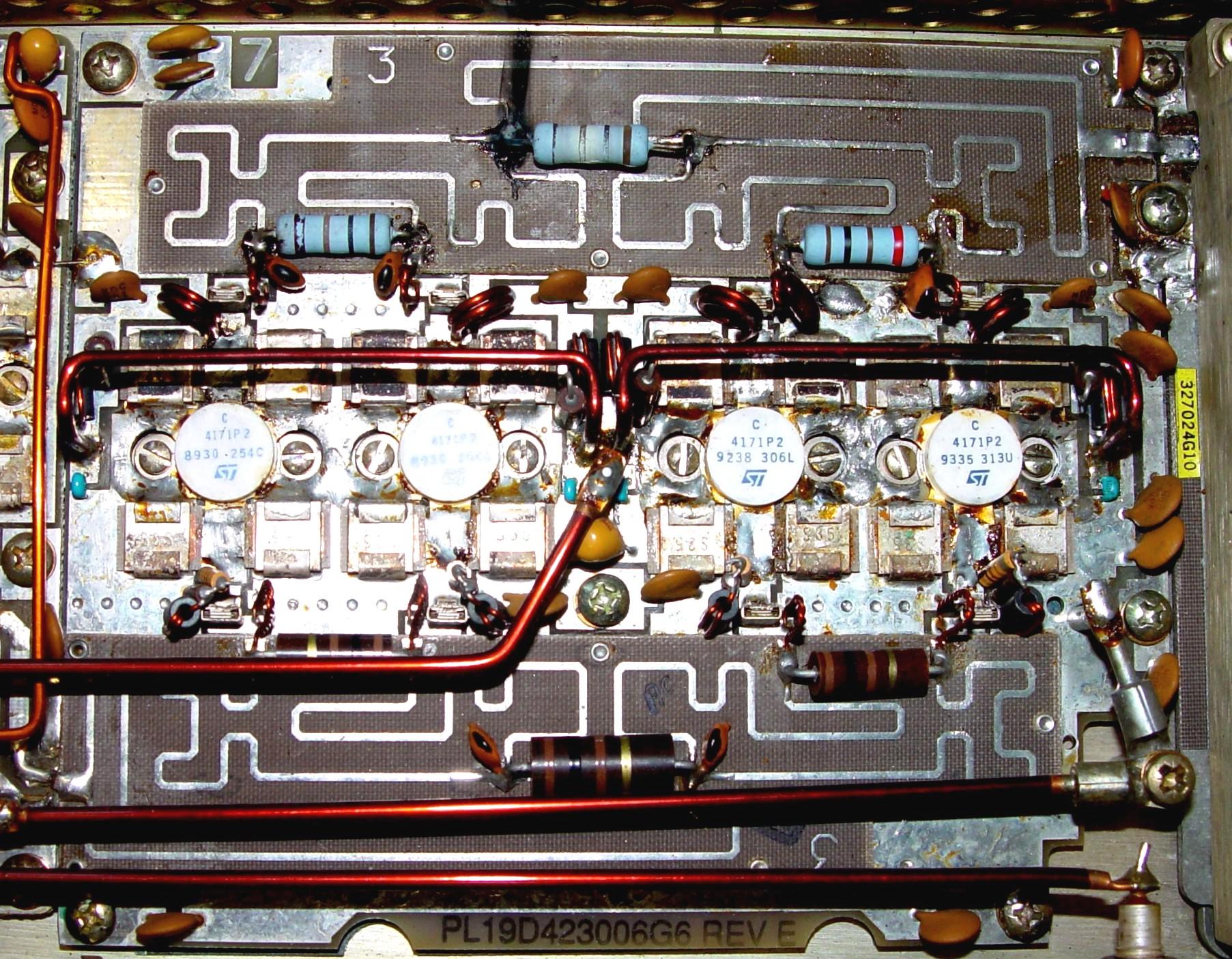
Joe asked me to repair the damage and replace the three resistors and four PA transistors.
I had never worked on this kind of equipment but I knew that Dave N1OFJ had some spare parts that he was going to give to Joe, figuring he'd never need them. Among those parts were at least a dozen brand new Allen Bradley 100 ohm 2-watt carbon resistors and a brand new matched quad of PA transistors marked 4171P2.
The resistors were R4208, R4209, and R4210, which form the output-balancing network, p/n 19A700111P39.
The transistors were Q216, Q217, Q218, and Q219, NPN, p/n 19A134171P2.
I downloaded two manuals from the Repeater-Builder web site to assist me with this endeavor. Dave also loaned me two big notebooks full of manuals for reference.
Disassembly:
The original balancing resistors had already been replaced, and the newer ones were only soldered to the top of the board. I decided to remove the PA circuit board to get to the solder side do a proper repair job and to see what damage had occurred there. Here are the steps I took:
I was then able to completely remove the PA module from the chassis.
Destruction and Removal:
As the people on the PBS television show "This Old House" always say, "You must destruct before you can construct."
I removed the three burned resistors. During the process, two of the four solder pads underneath the board fell off. I removed the burn marks from the circuit board. I removed the excess flux by scraping as much as I could and finished with a toothbrush and alcohol. This was the easy part.
Next, I began removing the four PA transistors. Each transistor has four emitter leads in an "X" pattern, one base lead, and one collector lead, indicated by a small "C" on the ceramic. See the image below:
![]()
I could see the base and collector leads that were pressed down onto leads of the metal capacitors, so I sucked as much solder off those areas as possible using a 140-watt soldering gun. (My good old 35-watt iron wouldn't make a dent in the connections.) I could barely pry the base and collector leads up using a knife blade. There just wasn't room to heat the lead and the capacitors and still get something between them to separate the leads. (I later discovered that some of my difficulty was caused by a broken soldering gun tip; it would heat if I applied pressure to the joint in a certain way. I'm glad I had a spare from 20 years ago.)
The emitter leads were impossible to separate from the capacitors. They were bent quite nicely against the body of the metal capacitors, and everything was thoroughly soldered to the ground foil on the circuit board. In addition, the entire underside of the circuit board is also a ground foil, and all of the capacitors are well soldered on both sides. While I could remove some solder, I still couldn't get a knife blade in the junction to separate the emitter leads from the capacitors.
Normally, I try to remove old parts intact, just because that's the way I do things. But since I was replacing them anyway, there was no reason to save the old transistors, so I took my knife and cut through the emitter leads right at the ceramic body, thus separating the transistor from the circuit board. I then was able to wiggle the part enough while applying heat, to get the base and collector leads free, and the part could be extracted from the board. Some heat from the soldering gun on each metal capacitor was enough to free the remaining piece of emitter lead and all 16 pieces came right off. I removed all the excess solder and smoothed the area on the ground foil. I also removed all of the flux from that area of the circuit board.
The metal capacitors seemed to be rather tarnished, so I used some liquid metal cleaner (Tarn-X) and a toothbrush to clean them. I rinsed the circuit board in warm water, shook out most of it, and used some compressed air to blow the rest away. I let the board dry out overnight.
Unfortunately, I neglected to take a photograph of the board in this condition. I wasn't thinking about using it as the basis of an article. But it looked nice and clean.
While I had the modules off the chassis, I removed the fiber insulator that was under the PA circuit board and removed the old heat-sink thermal compound from the chassis and the insulator. A brass wire brush completed the cleanup of the chassis.
Construction and Installation:
Now that all the bad or damaged parts have been removed, I can begin to rebuild the PA module.
The 2-watt resistors were installed, which included repositioning the solder pads underneath the circuit board. The burned trace was repaired using four pieces of #22 solid hookup wire, twisted around the resistor lead and flattened against the foil trace to bridge the gap. Everything was well soldered, top and bottom, using 2% silver solder, and the flux was removed.
I temporarily reinstalled the PA circuit board in the chassis, being careful to position it as it had been originally. I then dropped one of the PA transistors into the hole in the board to see what had to be bent to make them fit. I had read somewhere that the emitter leads might have to be cut to fit into the circuit. That seemed to be uncalled-for, so I just bent the leads upwards so they'd clear the sides of the metal capacitors. I then installed two screws through the transistor to hold it in position on the chassis. Using a screwdriver blade, I bent the emitter leads so they were flush with the circuit board, up against the side of the metal capacitors, and flat over the top edge. I also pushed the base and collector leads down into the slight depression formed by the capacitor leads. I used the soldering gun and 2% silver solder to reconnect all six leads of the transistor. I repeated this procedure on the other three transistors.
Mounting the transistors to the chassis acted as a very large heat sink (which, of course, it is) for the soldering process. I made sure the solder flowed all around the transistor leads by going back to each one and adding more solder if necessary.
I removed all the mounting hardware and inspected the soldering job. I found a few places underneath the circuit board that required some solder, so I added it where necessary. I cleaned the flux off the connections. I gave the board one final inspection and checked for obvious short circuits with an ohmmeter.
I put the fiber insulator on the chassis. I installed the PA circuit board to make sure the insulator cleared the transistors. Everything seemed good to go.
I removed the circuit board one last time, applied a thin coating of thermal heat-sink compound to the metal surface of each of the PA transistors, wiped it evenly around, and carefully installed the PA circuit board back into the chassis.
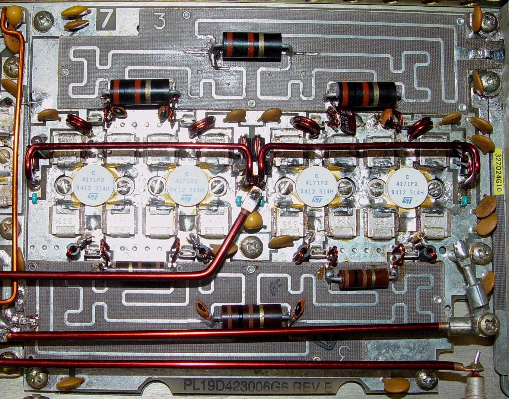
I made one final check across the main power wires for short circuits; there were none. Even though the new 2-watt resistors look like they have red-black-red color bands, they are in fact brown-black-brown color bands and measure 106 ohms each. See the photo below for the "after" image. Click on it for a larger view.
Final Tests:
I didn't want to see all of this effort go up in smoke in just a couple of microseconds, so I did NOT do any further testing, nor did I apply power to the amplifier. I leave that as a chore for the original owner. Technically, I just repaired or rebuilt the unit; I didn't "fix" it since I didn't test my work. The status of the unit when I got it was unknown, and rather than risk blowing it up because of another problem, I only performed the work noted above.
All of this work took me about 8 hours over a period of two days. Maybe I went overboard and took more apart than was actually necessary, but as it was my first time working on this make and model equipment, I don't think I did too bad. I'm sure an experienced technician or commercial radio shop wouldn't spend this much time on such an old unit; they would have sold the customer a new radio or system instead.
When I returned the amplifier to Joe, he gave me a very nice compliment on what a nice job I did, saying it looked like it came from the factory. "Not only a great job repairing the PA, but a well written article as well." What other way IS there to rebuild something?
Applicable Documents:
The following files were obtained from the GE section of the Repeater-Builder web site. Click on either link to retrieve the PDF file; they are large, around 3MB each.
LBI-30199D.PDF: Description and Maintenance - 406-512 MHz, 100 Watt MASTR II Transmitter.
LBI-30201G.PDF: Maintenance Manual - 406-512 MHz, 100 Watt Power Amplifier Assembly - 19D424895G14-17, G31-34, G38 and G39 (Continuous Duty Station).
Acknowledgements and Credits:
Thanks to Joe N1LES for giving me this P.I.T.A. project in the first place.
Thanks to Dave N1OFJ for providing some useful manuals and all of the spare parts.
MASTR II is a trademark of General Electric Company, or whoever has since taken over their mobile radio division.
The silver solder was purchased from Jameco, p/n 73605. This is 62% Tin, 36% Lead, and 2% Silver. It is made by Kester, has a diameter of 0.020 inches, and is sold in a small pocket-sized pack of a few ounces. At the time of this writing, it cost $2.85US.
Contact Information:
The author can be contacted at: his-callsign [ at ] comcast [ dot ] net.
Back to the top of the page
Up one level (GE index)
Back to Home
This page originally posted on Thursday 05-Jul-2007
Article text, artistic layout, and hand-coded HTML © Copyright 2007 by Robert W. Meister WA1MIK.
This web page, this web site, the information presented in and on its pages and in these modifications and conversions is © Copyrighted 1995 and (date of last update) by Kevin Custer W3KKC and multiple originating authors. All Rights Reserved, including that of paper and web publication elsewhere.