Step
by Step procedure for duplexing the MASTR II®
By Kevin Custer W3KKC
Build
a Repeater from a MASTR II
Read through this entire procedure before beginning.
Forward:
This modification is not for the faint-hearted. Although the MASTR
II® mobile radio system is by far the easiest of the commercial mobile
radios to convert to a repeater, you should be sure you are very comfortable
with the operation of the radio before you attempt this modification.
A thorough understanding of the way the MASTR II® radio and control
system work is absolutely essential for the success of this conversion.
A manual is not necessary, but is desired for comprehending the conversion
and tune-up.
That being said, support for your MASTR II conversion may be available
from a few resources.
These resources are listed below:
GE MASTR II Email List.
Repeater Elmers.
Email
support from the author.
Choosing a radio to convert:
These links will help you determine the best radio for your conversion
or tell you what you are about to buy:
Choosing a Radio
to Convert Information provided by the NHRC MASTR II
Infosite.
MASTR II Radio Combination Numbers (Nomenclature)
Concept:
The following instructions are provided to help convert a General Electric
MASTR II mobile 2-way radio to a repeater station. Modification of
the System Board and Front Panel Casting, for addition of a second antenna
port, allows the radio to operate full duplex. This modification
is intended for those who are using a newer type controller which provides
a means of muting and de-emphasizing the audio of the receiver. NHRC
controllers provide both functions; therefore an additional interface board
is unnecessary. This modification was written primarily for the NHRC/M2
controllers, however, the instructions can be followed to attach any controller.
The /M2 suffix refers to a type of controller which plugs right into the
MASTR II, in the spot formerly occupied by the original Channel Guard (CTCSS)
board. The /M2 controllers allow for a clean, slim line repeater
to be fashioned, with all support being contained within the chassis.
In actual repeater operation, a Control Head is not needed, nor usually
desired. A Control Head can be connected to the radio if a local
microphone is needed.
Caution:
The first thing to do is ensure your MASTR II is tuned up and working.
If the unit is being converted to the ham band, make sure the radio works
properly in its original band and split before any modifications are made.
This will allow you to repair any problems first, which could result in
really getting lost. Afterwards, retune the radio to the ham band
before any duplex modifications are made so you will know what to expect
as far as transmitter output power and receiver sensitivity are concerned.
The use of a control head and cable are necessary to insure the radio is
operating properly. Borrow a head and cable assembly from a friend
or visit the local 2-Way shop and see if they will test the radio set for
you. A BF10A key may be required to fold the handle down to remove
the top cover.
This part of the site may be helpful
in understanding the radio and powering it up without a control head.
Procedure:
-
If you haven't already done so, test your radio on the frequency it is
currently tuned. Then, re-crystal your channel ICOM's (crystal oscillator
module, or channel element) to your repeater frequencies. This is
done by either sending the ICOMs to a reputable crystal house or getting
replacement crystals and installing them into the elements yourself.
There are different types and combinations of ICOMs used in the MASTR
II. Go to this page from Hall
Electronics to understand all about them. Retune the radio to
the new frequencies by using a 'Test Set' or analog (needle
type) VOM and the Comprehensive
Tuning Procedures from the NHRC Infosite. You may need to use
your browsers "Back" button to return here. A simple
version of the tuning instructions for more experienced builders is
also available from the linked text.
-
Start the conversion by disassembling the radio set, which is done by removing
the outer covers and control head cable. Remember how you take the
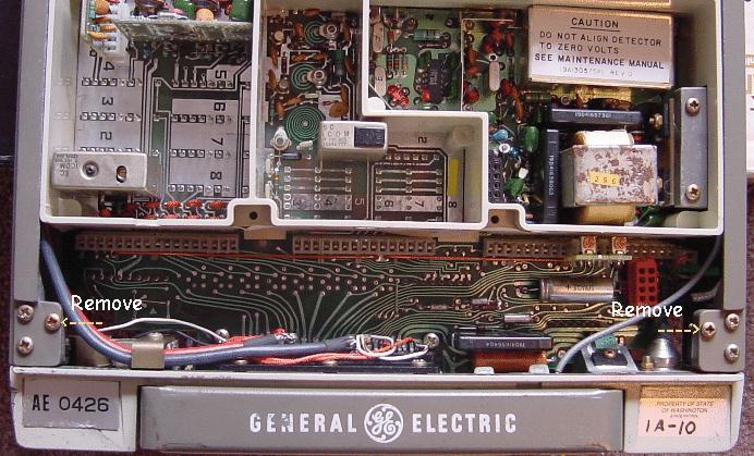
radio apart so you can get it back together as it was. Remove
the bottom cover by taking out the two screws indicated in the photo below.
-
I prefer to disassemble the whole radio to make it easier to get to the
System Board and Front Panel Casting. This makes it easier to add
the receiver antenna connection and do the modifications to the System
Board for full duplex.
This procedure is explained in detail in the next step.
You can also do the following steps without disassembling the
radio, however, care must be exercised when installing the jumpers on the
System Board as some of the contact points are slightly covered by the
edge of the front panel casting. Care must also be used when installing
the receiver antenna connection so you don't drill into the System Board.
-
Add the Receiver RF Antenna Connection
as outlined on the linked page.
-
Do the Duplex Modifications to the System
Board, as described on this linked page, before reassembling the front
panel casting onto the radio set.
-
After doing the System Board modifications, replace the System Board
back onto the front panel chassis and reassemble the radio. Use fresh
heat sink grease on the transistor, on the System Board, and the surface
between the audio amplifier pass transistor assembly and the left side
cover. Reassemble the radio, except for replacing the top and bottom
covers. Be sure to observe polarity on the power leads going to the
power amplifier.
-
Route the added receiver antenna coax cable to the input of the receiver
or preamp if installed. This can be done by running the coax next
to the existing antenna connector cable, by removing the side panel of
the radio chassis, or you can use the hole through the plastic support
to route the cable into the receiver oscillator area, and then over the
mixer/preselector casting and into the antenna jack.
-
Install a male RCA type plug on the other end of the receiver antenna cable.
I try to reuse one of the plugs from the T/R relay jumper; they seem
to be quite resistant to soldering heat. The molded plastic on these
plugs can be cut away with diagonal cutters, and the plastic inside the
connector body melted with a soldering iron and pulled out with a dental
pick. Whatever RCA plug you use, make sure the shield coverage is
as close to 100% as you can get. The main goal here is to make sure
that the antenna jack jumper is shielded extremely well. Do not cut corners
here!
-
Either terminate the speaker connections (SKR HI and SKR LO) with a local
speaker (jack) or a load resistor so the audio amp doesn't oscillate.
This can be done on the control head pins 27 and 28 or P904 pins 19 and
20. A load of some sort must be connected at all times or the radio
will produce funny sounds (snaps and pops) on the repeated audio.
-
Deal with the T/R Relay (or not?)
-
Decide what controller you are going to use. There are several different
schools of thought on interfacing MASTR II radios to repeater controllers.
This will determine the exact method of the conversion as you may need
to re-use the control head pins to interface the controller to the radio
set. If you are adding an external controller, use or re-use control
head pins to allow the connection of an outboard controller. If the
NHRC/M2 series controller is being used, there is no need to reconfigure
these pins unless you are wiring a remote base to an NHRC-4/M2.
Here are some examples:
1.) An interface cable for the repeater controller can be wired to the
control head.
2.) An interface cable for the repeater controller can be wired directly
into the radio's system board.
3.) A control cable can be "sacrificed" by cutting off the control
head plugs and installing a small box with volume and squelch controls
and an interface cable for the repeater controller.
4.) Some combination of the above.
In any event, consultation of the system board or control head schematics
are likely a must.
This page will help with the signals available from the Control
Head Plug.
-
Install the CTCSS decoder as needed.
Want
CTCSS only during COS activity with the NHRC-3/M2 and the Com-Spec TS-64? Click here.
Want CTCSS only during COS activity with
the NHRC-4/M2 and the Com-Spec TS-64? Click here.
-
Install a PTT Disable Switch. This switch can be easily installed
by cutting the PTT signal lead and inserting the switch in series with
it. The plastic wall between the exciter and receiver is a good place
to mount the switch. On radios with the common System Board you
will cut the trace between H72 and H85. This trace is found on the
component side of the System Board. Hole H85 is a feed-through that can
be voided of solder and a wire placed through the hole. Hole H72
is the right end of the delta jumper. I would suggest tack soldering the
other PTT disable lead to the delta jumper. A momentary push button
switch can also be placed and wired to enable the transmitter for testing.
We wire the PTT Test switch through the PTT Disable switch so you cannot
make the transmitter operate at all without the PTT Disable switch placed
in the operate position.
-
Install the Volume and Squelch Controls. There are several ways to
do this:
1) You can use the control head and cable as it was intended from the
factory.
2) You can remove the pots and install them inside the radio by drilling
the plastic wall between the compartments and wiring them directly.
3) Use the NHRC Vol/Sq pots.
This is the easy way out, and cheap too. This is the best approach
if you don't have a control head and don't plan on ever using one.
-
Add a length of quality power cable to the radio. This is done either
by drilling the Control Head Connector and soldering the leads to the heavy
pins on the back side of the connector or by scavenging the power leads
from a genuine Control Head Cable.
-
Set levels and program your controller.
-
Place the top and bottom covers back onto the radio set.
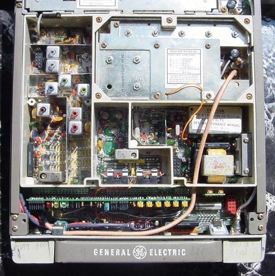
-
You are done! Picture of the completed repeater.
This site, its contents, and look & feel are Copyrighted©
Some information provided in cooperation with NHRC LLC, and their Infosite.
2001 Kevin Custer W3KKC
All Rights Reserved.